Example for Configuring an E-Trunk Associated with VPLS
This section provides an example for configuring an E-Trunk on PEs to implement device-level reliability when a CE is dual-homed to the PEs through Eth-Trunk interfaces.
Networking Requirements
Eth-Trunk implements link reliability between single devices. However, if a device fails, Eth-Trunk ceases to take effect.
To improve network reliability, carriers introduced the device redundancy method that requires master and backup devices. If the master device or primary link fails, the backup device can take over user services. In this situation, another device must be dual-homed to the master and backup devices, and inter-device link reliability must be ensured.
In dual-homing networking, Virtual Router Redundancy Protocol (VRRP) can be used to ensure device-level reliability, and Eth-Trunk can be used to ensure link reliability. In some cases, however, traffic cannot be switched to the backup device and secondary link simultaneously if the master device or primary link fails. As a result, traffic is interrupted. To address this issue, use Enhanced Trunk (E-Trunk) to implement both device-level and link reliability.
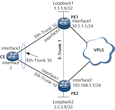
On the network shown in Figure 1, the CE is dual-homed to the PEs on the virtual private LAN service (VPLS) network using Eth-Trunk interfaces working in static LACP mode. To prevent service interruptions, deploy E-Trunk on PE1 and PE2 with PE1 as the master device and PE2 as the backup device. If PE1 or the Eth-Trunk link between PE1 and the CE fails, traffic from the CE is switched to PE2 and the CE enjoys non-stop communication with devices on the VPLS network through PE2. If PE1 or the Eth-Trunk link between the CE and PE1 recovers, traffic is switched back to PE1. In this manner, E-Trunk provides backup between PE1 and PE2, improving network reliability.
Precautions
E-Trunk is used to perform link protection in the networking where a CE is dual-homed to two PEs on a VPLS network and prevent service interruptions when a PE becomes faulty.
Configuration Roadmap
The configuration roadmap is as follows:
Configure VPLS on PE1 and PE2 so that users can communicate through the VPLS network.
Configure a routing protocol on PE1 and PE2 to ensure Layer 3 network connectivity.
OSPF is used as an example.
Configure basic Multiprotocol Label Switching (MPLS) functions and MPLS LDP on PE1 and PE2 and set up LDP LSPs.
Enable MPLS L2VPN on PE1 and PE2 so that the MPLS network transparently transmits user packets.
Configure a Virtual Switching Instance (VSI) on PE1 and PE2 and bind the VSI to an AC sub-interface on each PE so that the CE can access the VPLS network through the sub-interfaces.
Create Eth-Trunk interfaces working in static LACP mode on the CE and PEs and add member interfaces to the Eth-Trunk interfaces to implement Layer 2 forwarding and improve link reliability.
Configure an E-Trunk on PE1 and PE2 to improve device-level reliability.
Create an E-Trunk on PE1 and PE2 and added the Eth-Trunk interfaces on the PEs to the E-Trunk.
Bind a BFD session to the E-Trunk on PE1 and PE2 so that BFD can fast detect faults on the links between PE1 and PE2.
- Configure E-Trunk parameters to ensure reliable communication in the E-Trunk.
LACP system IDs and LACP priorities of the member Eth-Trunk interfaces in the E-Trunk
Priorities of the E-Trunk
Interval for sending Hello packets by the E-Trunk
Time multiplier for detecting Hello packets by the E-Trunk
Descriptions of the E-Trunk.
- E-Trunk security-key.
Data Preparation
To complete the configuration, you need the following data:
VSI IDs on each PE (VSI IDs on the PEs must be the same.)
MPLS LSR ID of each PE
Names of the VSIs on PE1 and PE2
Interfaces to which VSIs are bound
System ID of the E-Trunk
Local and peer IP addresses
LACP system IDs and LACP priorities of the member Eth-Trunk interfaces in the E-Trunk
Priorities of the E-Trunk
Period for sending Hello packets and time multiplier for detecting Hello packets
Procedure
- Configure VPLS.
Configure OSPF on PE1 and PE2.
# Assign an IP address to each member interface on each PE as shown in Figure 1. After OSPF is enabled, the 32-bit loopback address of each PE must be advertised.
# Configure PE1.
<HUAWEI> system-view
[~HUAWEI] sysname PE1
[*HUAWEI] commit
[~PE1] interface loopback 1
[*PE1-LoopBack1] ip address 1.1.1.9 255.255.255.255
[*PE1-LoopBack1] quit
[*PE1] interface gigabitethernet 0/1/1
[*PE1-GigabitEthernet0/1/1] undo shutdown
[*PE1-GigabitEthernet0/1/1] ip address 10.1.1.1 255.255.255.0
[*PE1-GigabitEthernet0/1/1] quit
[*PE1] ospf
[*PE1-ospf-1] area 0
[*PE1-ospf-1-area-0.0.0.0] network 1.1.1.9 0.0.0.0
[*PE1-ospf-1-area-0.0.0.0] network 10.1.1.0 0.0.0.255
[*PE1-ospf-1-area-0.0.0.0] quit
[*PE1-ospf-1] quit
[*PE1] commit
# Configure PE2.
<HUAWEI> system-view
[~HUAWEI] sysname PE2
[*HUAWEI] commit
[~PE2] interface loopback 1
[*PE2-LoopBack1] ip address 2.2.2.9 255.255.255.255
[*PE2-LoopBack1] quit
[*PE2] interface gigabitethernet 0/1/9
[*PE2-GigabitEthernet0/1/9] undo shutdown
[*PE2-GigabitEthernet0/1/9] ip address 192.168.1.1 255.255.255.252
[*PE2-GigabitEthernet0/1/9] quit
[*PE2] ospf
[*PE2-ospf-1] area 0
[*PE2-ospf-1-area-0.0.0.0] network 2.2.2.9 0.0.0.0
[*PE2-ospf-1-area-0.0.0.0] network 192.168.1.0 0.0.0.255
[*PE2-ospf-1-area-0.0.0.0] quit
[*PE2-ospf-1] quit
[*PE2] commit
After the configuration is complete, PE1and PE2 can discover IP routes of the peer loopback1 by OSPF. The IP addresses in these routes can ping each other.
[~PE1] ping 2.2.2.9
  PING 2.2.2.9: 56  data bytes, press CTRL_C to break
    Reply from 2.2.2.9: bytes=56 Sequence=1 ttl=254 time=5 ms
    Reply from 2.2.2.9: bytes=56 Sequence=2 ttl=254 time=2 ms
    Reply from 2.2.2.9: bytes=56 Sequence=3 ttl=254 time=2 ms
    Reply from 2.2.2.9: bytes=56 Sequence=4 ttl=254 time=2 ms
    Reply from 2.2.2.9: bytes=56 Sequence=5 ttl=254 time=2 ms

  --- 2.2.2.9 ping statistics ---
    5 packet(s) transmitted
    5 packet(s) received
    0.00% packet loss
    round-trip min/avg/max = 2/2/5 ms
Enable basic MPLS functions and LDP on the MPLS backbone network.
# Configure PE1.
[~PE1] mpls lsr-id 1.1.1.9
[*PE1] mpls
[*PE1-mpls] quit
[*PE1] mpls ldp
[*PE1-mpls-ldp] quit
[*PE1] interface gigabitethernet 0/1/1
[*PE1-GigabitEthernet0/1/1] mpls
[*PE1-GigabitEthernet0/1/1] mpls ldp
[*PE1-GigabitEthernet0/1/1] quit
[*PE1] commit
# Configure PE2.
[~PE2] mpls lsr-id 2.2.2.9
[*PE2] mpls
[*PE2-mpls] quit
[*PE2] mpls ldp
[*PE2-mpls-ldp] quit
[*PE2] interface gigabitethernet 0/1/9
[*PE2-GigabitEthernet0/1/9] mpls
[*PE2-GigabitEthernet0/1/9] mpls ldp
[*PE2-GigabitEthernet0/1/9] quit
[*PE2] commit
After the preceding configurations are complete, LDP sessions are set up between the PEs. Run the display mpls ldp session command and you can see that the Status field displays Operational.
Use the display on PE1 as an example:
[~PE1] display mpls ldp session
 LDP Session(s) in Public Network
 Codes: LAM(Label Advertisement Mode), SsnAge Unit(DDDD:HH:MM)
 An asterisk (*) before a session means the session is being deleted.
--------------------------------------------------------------------------
 PeerID             Status      LAM  SsnRole  SsnAge       KASent/Rcv
--------------------------------------------------------------------------
 2.2.2.9:0          Operational DU   Passive  0000:00:00   1/1
--------------------------------------------------------------------------
TOTAL: 1 Session(s) Found.

If PEs are indirectly connected, run the mpls ldp remote-peer and remote-ip commands to set up remote LDP sessions between the PEs.
Enable MPLS L2VPN on each PE.
# Configure PE1.
[~PE1] mpls l2vpn
[*PE1-l2vpn] quit
[*PE1] commit
# Configure PE2.
[~PE2] mpls l2vpn
[*PE2-l2vpn] quit
[*PE2] commit
Configure VSIs and bind the VSIs to AC sub-interfaces.
# Configure PE1.
[~PE1] vsi ldp1 static
[*PE1-vsi-ldp1] pwsignal ldp
[*PE1-vsi-ldp1-ldp] vsi-id 2
[*PE1-vsi-ldp1-ldp] peer 2.2.2.9
[*PE1-vsi-ldp1-ldp] mac-withdraw enable
[*PE1-vsi-ldp1-ldp] interface-status-change mac-withdraw enable
[*PE1-vsi-ldp1-ldp] quit
[*PE1-vsi-ldp1] ignore-ac-state
[*PE1-vsi-ldp1] quit
[*PE1] interface Eth-Trunk 10
[*PE1-Eth-Trunk10] quit
[*PE1] interface Eth-Trunk 10.1
[*PE1-Eth-Trunk10.1] vlan-type dot1q 1
[*PE1-Eth-Trunk10.1] l2 binding vsi ldp1
[*PE1-Eth-Trunk10.1] quit
[*PE1] commit
# Configure PE2.
[~PE2] vsi ldp1 static
[*PE2-vsi-ldp1] pwsignal ldp
[*PE2-vsi-ldp1-ldp] vsi-id 2
[*PE2-vsi-ldp1-ldp] peer 1.1.1.9
[*PE2-vsi-ldp1-ldp] mac-withdraw enable
[*PE2-vsi-ldp1-ldp] interface-status-change mac-withdraw enable
[*PE2-vsi-ldp1-ldp] quit
[*PE2-vsi-ldp1] ignore-ac-state
[*PE2-vsi-ldp1] quit
[*PE2] interface Eth-Trunk 10
[*PE2-Eth-Trunk10] quit
[*PE2] interface Eth-Trunk 10.1
[*PE2-Eth-Trunk10.1] vlan-type dot1q 1
[*PE2-Eth-Trunk10.1] l2 binding vsi ldp1
[*PE2-Eth-Trunk10.1] quit
[*PE2] commit

When a CE is dual-homed to two PEs on a VPLS network, if the master PE does not instruct its remote peers to update the MAC address entries in their VSIs when the AC status changes, traffic loss may occur due to invalid MAC addresses. To prevent traffic loss when a CE is dual-homed to two PEs on a VPLS network, run the mac-withdraw enable and interface-status-change mac-withdraw enable commands to enable the master PE to instruct its remote peers to update the MAC address entries in their VSIs by sending MAC Withdraw messages when the AC status changes.
To allow a VSI to ignore AC status changes, run the ignore-ac-state command. After this command is run, the VSI can be Up even if it is not bound to any AC sub-interface. Exercise caution when running this command.
# Run the display vsi name ldp1 verbose command. You can view information about PWs.
Use the display on PE1 as an example:
[~PE1] display vsi name ldp1 verbose
 ***VSI Name               : ldp1
    Administrator VSI      : no
    Isolate Spoken         : disable
    VSI Index              : 1
    PW Signaling           : ldp
    Member Discovery Style : static
    Bridge-domain Mode     : disable
    PW MAC Learn Style     : unqualify
    Encapsulation Type     : vlan
    MTU                    : 1500
    Ignore AcState         : enable
    P2P VSI                : disable
    Create Time            : 0 days, 0 hours, 41 minutes, 35 seconds
    VSI State              : up
    Resource Status        : --

VSI ID                 : 2
   *Peer Router ID         : 2.2.2.9
    primary or secondary   : primary
    ignore-standby-state   : no
    VC Label               : 32828
    Peer Type              : dynamic
    Session                : up
    Tunnel ID              :0x0000000001004c4b42
    Broadcast Tunnel ID    : --
    Broad BackupTunnel ID  : --
    CKey                   : 1
    NKey                   : 3607101554
    Stp Enable             : 0
    PwIndex                : 1
    Control Word           : disable

    Interface Name         : Eth-Trunk10.1
    State                  : up
    Access Port            : false
    Last Up Time           : 2013/07/05 15:32:50
    Total Up Time          : 0 days, 0 hours, 8 minutes, 22 seconds

   **PW Information:

   *Peer Ip Address        : 2.2.2.9
    PW State               : up
    Local VC Label         : 19456
    Remote VC Label        : 19456
    Remote Control Word    : disable
    PW Type                : label
    Tunnel ID              : 0x0000000001004c4b42
    Broadcast Tunnel ID    : --
    Broad BackupTunnel ID  : --
    Ckey                   : 0x2
    Nkey                   : 0x1
    Main PW Token          : 0x801002
    Slave PW Token         : 0x0
    Tnl Type               : ldp
    OutInterface           : GigabitEthernet0/1/1
    Stp Enable             : 0
    Mac Flapping           : 0
    PW Last Up Time        : 2013/07/05 15:12:13
    PW Total Up Time       : 0 days, 0 hours, 26 minutes, 39 seconds
The preceding information indicates that a PW is set up between the PE1 and PE2 in the VSI named ldp1, the VSI and PW are all Up, and the Eth-Trunk sub-interface to which the VSI is bound is also Up.
- Configure the Layer 2 forwarding function on the CE, PE.
# Configure CE.
# Add the configured Eth-Trunk 10 to VLAN 1.
<HUAWEI> system-view
[~HUAWEI] sysname CE
[*HUAWEI] commit
[~CE] interface eth-trunk 10
[*CE-Eth-Trunk10] portswitch
[*CE-Eth-Trunk10] quit
[*CE] vlan 1
[*CE-vlan1] port eth-trunk 10
[*CE-vlan1] quit
[*CE] interface eth-trunk 10
[*CE-Eth-Trunk10] port link-type trunk
[*CE-Eth-Trunk10] port trunk allow-pass vlan 1
[*CE-Eth-Trunk10] mode lacp-static
[*CE-Eth-Trunk10] quit
[*CE] commit
# Add member interfaces to Eth-Trunk 10.
[~CE] interface gigabitethernet 0/1/1
[*CE-GigabitEthernet0/1/1] undo shutdown
[*CE-GigabitEthernet0/1/1] eth-trunk 10
[*CE-GigabitEthernet0/1/1] quit
[*CE] interface gigabitethernet 0/1/9
[*CE-GigabitEthernet0/1/9] undo shutdown
[*CE-GigabitEthernet0/1/9] eth-trunk 10
[*CE-GigabitEthernet0/1/9] quit
[*CE] commit
# Configure PE1.
[~PE1] interface eth-trunk 10
[*PE1-Eth-Trunk10] mode lacp-static
[*PE1-Eth-Trunk10] quit
[*PE1] interface gigabitethernet 0/1/9
[*PE1-GigabitEthernet0/1/9] undo shutdown
[*PE1-GigabitEthernet0/1/9] eth-trunk 10
[*PE1-GigabitEthernet0/1/9] quit
[*PE1] commit
# Configure PE2.
[~PE2] interface eth-trunk 10
[*PE2-Eth-Trunk10] mode lacp-static
[*PE2-Eth-Trunk10] quit
[*PE2] interface gigabitethernet 0/1/1
[*PE2-GigabitEthernet0/1/1] undo shutdown
[*PE2-GigabitEthernet0/1/1] eth-trunk 10
[*PE2-GigabitEthernet0/1/1] quit
[*PE2] commit
- Configure an E-Trunk.
Create Eth-Trunk 10 and configure it to work in static LACP mode.
# Configure PE1.
[~PE1] e-trunk 1
[*PE1-e-trunk-1] quit
[*PE1] interface eth-trunk 10
[*PE1-Eth-Trunk10] e-trunk 1
[*PE1-Eth-Trunk10] quit
[*PE1] commit
# Configure PE2.
[~PE2] e-trunk 1
[*PE2-e-trunk-1] quit
[*PE2] interface eth-trunk 10
[*PE2-Eth-Trunk10] e-trunk 1
[*PE2-Eth-Trunk10] quit
[*PE2] commit
Bind the E-Trunk to a BFD session.
Configure IP addresses for the local and peer ends of the E-Trunk.
# Configure PE1.
[~PE1] e-trunk 1
[*PE1-e-trunk-1] peer-address 2.2.2.9 source-address 1.1.1.9
[*PE1-e-trunk-1] security-key cipher 00E0FC000000
[*PE1-e-trunk-1] quit
[*PE1] commit
# Configure PE2.
[~PE2] e-trunk 1
[*PE2-e-trunk-1] peer-address 1.1.1.9 source-address 2.2.2.9
[*PE2-e-trunk-1] security-key cipher 00E0FC000000
[*PE2-e-trunk-1] quit
[*PE2] commit
Create a BFD session.
# Configure PE1.
[~PE1] bfd
[*PE1-bfd] quit
[*PE1] bfd hello bind peer-ip 2.2.2.9 source-ip 1.1.1.9
[*PE1-bfd-session-hello] discriminator local 1
[*PE1-bfd-session-hello] discriminator remote 2
[*PE1-bfd-session-hello] commit
[~PE1-bfd-session-hello] quit
[~PE1] commit
# Configure PE2.
[~PE2] bfd
[*PE2-bfd] quit
[*PE2] bfd hello bind peer-ip 1.1.1.9 source-ip 2.2.2.9
[*PE2-bfd-session-hello] discriminator local 2
[*PE2-bfd-session-hello] discriminator remote 1
[*PE2-bfd-session-hello] commit
[~PE2-bfd-session-hello] quit
[~PE2] commit
The IP addresses of the local and peer ends of a BFD session must be the same as that of the E-Trunk.
Bind the E-Trunk to a BFD session.
# Configure PE1.
[~PE1] e-trunk 1
[*PE1-e-trunk-1] e-trunk track bfd-session session-name hello
[*PE1-e-trunk-1] quit
[*PE1] commit
# Configure PE2.
[~PE2] e-trunk 1
[*PE2-e-trunk-1] e-trunk track bfd-session session-name hello
[*PE2-e-trunk-1] quit
[*PE2] commit
After the preceding configurations are complete, run the display bfd session all verbose command on PE1 and PE2. The command output shows that the BFD session has been created and is in the Up state.
Use the display on PE1 as an example:
[~PE1] display bfd session all verbose
(w): State in WTR
(*): State is invalid
--------------------------------------------------------------------------------
  (Multi Hop) State : Up                    Name : hello
--------------------------------------------------------------------------------
  Local Discriminator    : 1                Remote Discriminator   : 2
  Session Detect Mode    : Asynchronous Mode Without Echo Function
  BFD Bind Type          : Peer IP Address
  Bind Session Type      : Static
  Bind Peer IP Address   : 2.2.2.9
  Bind Interface         : -
  Track Interface        : -
  Bind Source IP Address : 1.1.1.9
  FSM Board Id           : 9                TOS-EXP                : 7
  Min Tx Interval (ms)   : 10               Min Rx Interval (ms)   : 10
  Actual Tx Interval (ms): 10               Actual Rx Interval (ms): 10
  Local Detect Multi     : 3                Detect Interval (ms)   : 30
  Echo Passive           : Disable          Acl Number             : -
  Destination Port       : 4784             TTL                    : 254
  Proc Interface Status  : Disable          Process PST            : Disable
  WTR Interval (ms)      : -                Config PST             : Disable
  Active Multi           : 3
  Last Local Diagnostic  : Neighbor Signaled Session Down(Receive AdminDown)
  Bind Application       : E-TRUNK
  Session TX TmrID       : -                Session Detect TmrID   : -
  Session Init TmrID     : -                Session WTR TmrID      : -
  Session Echo Tx TmrID  : -
  Session Description    : -
--------------------------------------------------------------------------------

    Total UP/DOWN Session Number : 1/0
Configure E-Trunk parameters.
Configure LACP priorities and LACP system IDs for the member Eth-Trunk interfaces in the E-Trunk.
# Configure PE1.
[~PE1] lacp e-trunk priority 1
[*PE1] lacp e-trunk system-id 00e0-fc12-3458
[*PE1] commit
# Configure PE2.
[~PE2] lacp e-trunk priority 1
[*PE2] lacp e-trunk system-id 00e0-fc12-3458
[*PE2] commit
Member Eth-Trunk interfaces in the same E-Trunk must have the same LACP priority and LACP system ID.
Configure E-Trunk priorities.
# Configure PE1.
[~PE1] e-trunk 1
[*PE1-e-trunk-1] priority 10
# Configure PE2.
[~PE2] e-trunk 1
[*PE2-e-trunk-1] priority 20
Configure the period for sending Hello packets by the E-Trunk.
# Configure PE1.
[*PE1-e-trunk-1] timer hello 9# Configure PE2.
[*PE2-e-trunk-1] timer hello 9Configure the time multiplier for detecting Hello packets by the E-Trunk.
# Configure PE1.
[*PE1-e-trunk-1] timer hold-on-failure multiplier 30# Configure PE2.
[*PE2-e-trunk-1] timer hold-on-failure multiplier 30Configure the description of the E-Trunk.
# Configure PE1.
[*PE1-e-trunk-1] description PE1_to_PE2
[*PE1-e-trunk-1] quit
[*PE1] commit
# Configure PE2.
[*PE2-e-trunk-1] description PE2_to_PE1
[*PE2-e-trunk-1] quit
[*PE2] commit
- Verify the configuration.
# Run the display eth-trunk command on the CE. You can view the configuration of the Eth-Trunk interface.
[~CE] display eth-trunk 10
Eth-Trunk10's state information is:
Local:
LAG ID: 10                  WorkingMode: STATIC
Preempt Delay: Disabled     Hash arithmetic: According to flow
System Priority: 32768      System ID: 00e0-fc12-3459
Least Active-linknumber: 1  Max Active-linknumber: 16
Operate status: up          Number Of Up Port In Trunk: 1
Timeout Period: Slow
--------------------------------------------------------------------------------
ActorPortName                 Status   PortType PortPri PortNo PortKey PortState Weight
GigabitEthernet0/1/1          Selected 100M     32768   128    2593    11111100  1
GigabitEthernet0/1/9          Unselect 100M     32768   129    2593    11100010  1

Partner:
--------------------------------------------------------------------------------
ActorPortName              SysPri    SystemID       PortPri PortNo  PortKey   PortState
GigabitEthernet0/1/1          1      00e0-fc12-3458  32768  129     2593      11111100
GigabitEthernet0/1/9          1      00e0-fc12-3458  32768  32896   2593      11010000
The command output on the CE shows that the member interfaces GigabitEthernet 0/1/1 and GigabitEthernet in the Selected and Unselect state respectively.
# Run the display e-trunk command. You can view information about the E-Trunk.
[~PE1] display e-trunk 1
                            The E-Trunk information
E-TRUNK-ID : 1                          Revert-Delay-Time (s) : 120
Priority : 10                           System-ID : 00e0-fc12-3457
Peer-IP : 2.2.2.9                       Source-IP : 1.1.1.9
State : Master                          Causation : PRI
Send-Period (100ms) : 9                 Fail-Time (100ms) : 270
Receive : 1149                          Send : 1182
RecDrop : 0                             SndDrop : 0
Peer-Priority : 20                      Peer-System-ID : 00e0-fc12-3456
Peer-Fail-Time (100ms) : 270            BFD-Session : hello
Description : PE1_to_PE2
--------------------------------------------------------------------------------
                            The Member information
Type      ID  LocalPhyState  Work-Mode     State   Causation        Remote-ID
Eth-Trunk 10  Up             auto          Master  PEER_MEMBER_DOWN 10
[~PE2] display e-trunk 1
                            The E-Trunk information
E-TRUNK-ID : 1                          Revert-Delay-Time (s) : 120
Priority : 20                           System-ID : 00e0-fc12-3456
Peer-IP : 1.1.1.9                       Source-IP : 2.2.2.9
State : Backup                          Causation : PRI
Send-Period (100ms) : 9                 Fail-Time (100ms) : 270
Receive : 1435                          Send : 1438
RecDrop : 35                            SndDrop : 0
Peer-Priority : 10                      Peer-System-ID : 00e0-fc12-3457
Peer-Fail-Time (100ms) : 270            BFD-Session : hello
Description : PE2_to_PE1
--------------------------------------------------------------------------------
                            The Member information
Type      ID  LocalPhyState  Work-Mode     State   Causation        Remote-ID
Eth-Trunk 10  Down           auto          Backup  PEER_MEMBER_UP   10
The command output shows that the E-Trunk priority on PE1 is 10 and the status of the E-Trunk on PE1 is master, and the E-Trunk priority on PE2 is 20, and the status of the E-Trunk on PE2 is backup. This implements link backup between PE1 and PE2.
Configuration Files
Configuration file of the CE
#
sysname CE
#
vlan batch 1
#
interface Eth-Trunk10
 portswitch
 port link-type trunk
 port trunk allow-pass vlan 1
 mode lacp-static
#
interface GigabitEthernet0/1/1
 undo shutdown
 eth-trunk 10
#
interface GigabitEthernet0/1/9
 undo shutdown
 eth-trunk 10
#
return
Configuration file of the PE1
#
sysname PE1
#
lacp e-trunk system-id 00e0-fc12-3458
lacp e-trunk priority 1
#
bfd
#
mpls lsr-id 1.1.1.9
#
mpls
#
mpls l2vpn
#
vsi ldp1 static
 pwsignal ldp
  vsi-id 2
  mac-withdraw enable
  interface-status-change mac-withdraw enable
  peer 2.2.2.9
 ignore-ac-state
#
mpls ldp
#
mpls ldp remote-peer 2.2.2.9
#
mpls ldp remote-peer PE2
 remote-ip 2.2.2.9
#
e-trunk 1
 priority 10
 peer-address 2.2.2.9 source-address 1.1.1.9
 timer hello 9
 timer hold-on-failure multiplier 30
 e-trunk track bfd-session session-name hello
 description PE1_to_PE2
 security-key cipher ***
#
interface Eth-Trunk10
 mode lacp-static
 e-trunk 1
#
interface Eth-Trunk10.1
 vlan-type dot1q 1
 l2 binding vsi ldp1
#
interface GigabitEthernet0/1/1
 undo shutdown
 ip address 10.1.1.1 255.255.255.0
 mpls
 mpls ldp
#
interface GigabitEthernet0/1/9
 undo shutdown
 eth-trunk 10
#
interface LoopBack1
 ip address 1.1.1.9 255.255.255.255
#
bfd hello bind peer-ip 2.2.2.9 source-ip 1.1.1.9
 discriminator local 1
 discriminator remote 2
#
ospf 1
 area 0.0.0.0
  network 1.1.1.9 0.0.0.0
  network 10.1.1.0 0.0.0.255
#
return
Configuration file of the PE2
#
sysname PE2
lacp e-trunk system-id 00e0-fc12-3458
lacp e-trunk priority 1
#
bfd
#
mpls lsr-id 2.2.2.9
#
mpls
#
mpls l2vpn
#
vsi ldp1 static
 pwsignal ldp
  vsi-id 2
  mac-withdraw enable
  interface-status-change mac-withdraw enable
  peer 1.1.1.9
 ignore-ac-state
#
mpls ldp
#
mpls ldp remote-peer PE1
 remote-ip 1.1.1.9
#
e-trunk 1
 priority 20
 peer-address 1.1.1.9 source-address 2.2.2.9
 timer hello 9
 timer hold-on-failure multiplier 30
 e-trunk track bfd-session session-name hello
 description PE2_to_PE1
 security-key cipher ***
#
interface Eth-Trunk10
 mode lacp-static
 e-trunk 1
#
interface Eth-Trunk10.1
 vlan-type dot1q 1
 l2 binding vsi ldp1
#
interface GigabitEthernet0/1/1
 undo shutdown
 eth-trunk 10
#
interface GigabitEthernet0/1/9
 undo shutdown
 ip address 192.168.1.1 255.255.255.0
 mpls
 mpls ldp
#
interface LoopBack1
 ip address 2.2.2.9 255.255.255.255
#
bfd hello bind peer-ip 1.1.1.9 source-ip 2.2.2.9
 discriminator local 2
 discriminator remote 1
#
ospf 1
 area 0.0.0.0
  network 2.2.2.9 0.0.0.0
  network 192.168.1.0 0.0.0.255
#
return