Example for Configuring Eth-Trunk Sub-interfaces to Support Communication Between VLANs
To enable the communication between devices in different VLANs, you can create Eth-Trunk sub-interfaces on the Eth-Trunk interfaces that connect a router to switches, configure 802.1Q encapsulation and an IP address on each sub-interface, and associate each sub-interface with a VLAN. In this manner, communication between VLANs can be implemented through the router and switches.
Networking Requirements
Users in different communities and network segments require the same services, such as Internet, IPTV, and VoIP services. The network administrator in each community configures a VLAN for each service to simplify management. After the configuration, users in different communities belong to different VLANs, but the users need to communicate with each other for the same services. In addition, traffic load balancing must be implemented and link bandwidth improved to ensure communication quality.
On the network shown in Figure 1, users in communities 1 to 4 belong to different VLANs and network segments but all require the Internet service. These users must be able to communicate with each other.
Precautions
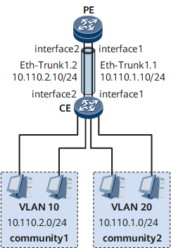
The host IP addresses in VLAN 10 and the IP address of Eth-Trunk 1.2 must be in the same network segment.
The host IP addresses in VLAN 20 and the IP address of Eth-Trunk 1.1 must be in the same network segment.
Configuration Roadmap
The configuration roadmap is as follows:
Create an Eth-Trunk sub-interface on each PE and assign an IP address for the sub-interface for reachable Layer 3 routes.
Configure 802.1Q as the encapsulation mode for each Eth-Trunk sub-interface and associate the sub-interface with a VLAN to use Eth-Trunk sub-interfaces to provide access services for users in different VLANs.
Data Preparation
To complete the configuration, you need the following data:
IDs of Eth-Trunk interfaces and their member interfaces on PE
Associated VLAN IDs and IP addresses of Eth-Trunk sub-interfaces on PE
IDs of Eth-Trunk interfaces and their member interfaces on switches

For detailed configurations of the switches, see the configuration guides for the switches.
Procedure
- Create Eth-Trunk sub-interfaces and assign IP addresses to them.
# Configure the PE.
<HUAWEI> system-view
[~HUAWEI] sysname PE
[*HUAWEI] commit
# Create Eth-Trunk 1.
[~PE] interface eth-trunk 1
[*PE-Eth-Trunk1] quit
# Add GE 0/1/1 and GE 0/1/9 to Eth-Trunk 1.
[*PE] interface gigabitethernet 0/1/1
[*PE-GigabitEthernet0/1/1] undo shutdown
[*PE-GigabitEthernet0/1/1] eth-trunk 1
[*PE-GigabitEthernet0/1/1] commit
[*PE-GigabitEthernet0/1/1] quit
[*PE] interface gigabitethernet 0/1/9
[*PE-GigabitEthernet0/1/9] undo shutdown
[*PE-GigabitEthernet0/1/9] eth-trunk 1
[*PE-GigabitEthernet0/1/9] commit
[~PE-GigabitEthernet0/1/9] quit
# Create Eth-Trunk 1.1 and assign an IP address to it.
[*PE] interface eth-trunk 1.1
[*PE-Eth-Trunk1.1] ip address 10.110.1.10 24
# Create Eth-Trunk 1.2 and assign an IP address to it.
[*PE] interface eth-trunk 1.2
[*PE-Eth-Trunk1.2] ip address 10.110.2.10 24
- Configure the encapsulation mode for each Eth-Trunk sub-interface and associate the sub-interfaces with a VLAN.
# Encapsulate Eth-Trunk 1.1 with 802.1Q and associate it with VLAN 10.
[*PE-Eth-Trunk1.1] vlan-type dot1q 20
[*PE-Eth-Trunk1.1] commit
[~PE-Eth-Trunk1.1] quit
# Encapsulate Eth-Trunk 1.2 with 802.1Q and associate it with VLAN 10.
[*PE-Eth-Trunk1.2] vlan-type dot1q 10
[*PE-Eth-Trunk1.2] commit
[~PE-Eth-Trunk1.2] quit
- Verify the configuration.
Assign IP addresses in the same network segment of the IP address of Eth-Trunk 1.2 to the hosts in VLAN 10. Specify the IP address 10.110.2.10/24 of Eth-Trunk 1.2 as the default gateway.
Assign IP addresses in the same network segment of the IP address of Eth-Trunk 1.1 to the hosts in VLAN 20. Specify the IP address 10.110.1.10/24 of Eth-Trunk 1.1 as the default gateway.
After the configuration, the hosts in VLAN 10 and VLAN 20 can ping each other successfully.
PE configuration file
#
sysname PE
#
interface Eth-Trunk1
 #
interface Eth-Trunk1.1
 vlan-type dot1q 20
 ip address 10.110.1.10 255.255.255.0
#
interface Eth-Trunk1.2
 vlan-type dot1q 10
 ip address 10.110.2.10 255.255.255.0
#
interface GigabitEthernet0/1/1
 undo shutdown
 eth-trunk 1
#
interface GigabitEthernet0/1/9
 undo shutdown
 eth-trunk 1
#
return