Example for Configuring the EVC Model to Carry VPLS Services (in VSI Pipe Service Mode)
This section provides an example for configuring the EVC model for a Virtual Switching Instance (VSI) to carry traffic from multiple BDs.
Networking Requirements
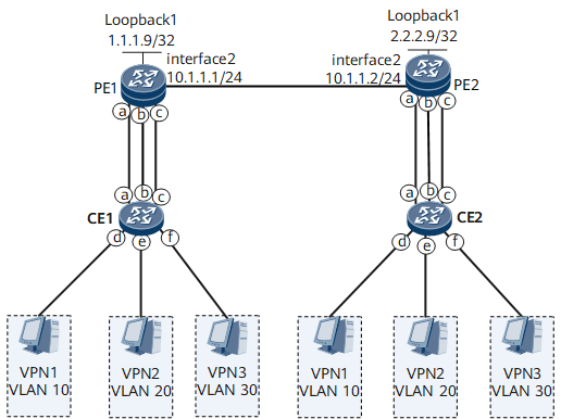
On the network shown in Figure 1, VLAN is used as the VSI encapsulation type, a VSI is configured as a network-side pipe, and BDs are configured as service instances at the access layer. The VSI can carry service traffic from multiple BDs. To ensure different sites in a VPN to communicate, bind the BDs to the VSI and configure different pseudowire (PW) tags to identify the BDs.

Interface 2 in this example represents GE 0/1/2.
Device |
No. |
Interface |
BD |
VLAN |
|---|---|---|---|---|
PE1 |
a |
GE0/1/1.1 |
BD 10 |
VLAN10 |
b |
GE0/1/1.2 |
BD 20 |
VLAN20 |
|
c |
GE0/1/1.3 |
BD 20 |
VLAN30 |
|
CE1 |
a |
GE0/1/2 |
— |
VLAN10 |
b |
GE0/1/4 |
— |
VLAN20 |
|
c |
GE0/1/6 |
— |
VLAN30 |
|
d |
GE0/1/1 |
— |
VLAN10 |
|
e |
GE0/1/3 |
— |
VLAN20 |
|
f |
GE0/1/5 |
— |
VLAN30 |
|
PE2 |
a |
GE0/1/1.1 |
BD 10 |
VLAN10 |
b |
GE0/1/1.2 |
BD 20 |
VLAN20 |
|
c |
GE0/1/1.3 |
BD 20 |
VLAN30 |
|
CE2 |
a |
GE0/1/2 |
— |
VLAN10 |
b |
GE0/1/4 |
— |
VLAN20 |
|
c |
GE0/1/6 |
— |
VLAN30 |
|
d |
GE0/1/1 |
— |
VLAN10 |
|
e |
GE0/1/3 |
— |
VLAN20 |
|
f |
GE0/1/5 |
— |
VLAN30 |
Precautions
PWs are used on VPLS networks to carry services and process service packets based on the VSI encapsulation type. If the VSI pipe service mode is used, the VSI encapsulation type must be VLAN.
Configuration Roadmap
The configuration roadmap is as follows:
Configure Layer 2 forwarding on the CEs.
- Create VLANs on each CE and add the CE's downstream interfaces to the corresponding VLANs.
- Configure Layer 2 forwarding on the CE's upstream interfaces so that the packets sent from a CE to a PE carry one VLAN tag.
Configure VPLS on the PEs.
- Configure a routing protocol on the PEs so that they can communicate at the network layer.
- Configure basic Multiprotocol Label Switching (MPLS) functions, enable MPLS Label Distribution Protocol (LDP), and establish LDP Label Switched Paths (LSPs) on the PEs.
- Enable MPLS L2VPN on the PEs globally.
- Create a VSI and configure Label Distribution Protocol (LDP) signaling. (VSI IDs are used to identify VSIs and used for PW signaling negotiation.)
- Establish the EVC model on the PEs.
- Configure BDs to forward services.
- Create EVC Layer 2 sub-interfaces and add them to BDs. Configure the traffic encapsulation type and flow behavior for the downstream interfaces.
- Bind the BDs to the VSI so that the EVC model can be used to carry VPLS services.
Data Preparation
- User VLAN IDs
- Numbers of the CE interfaces that connect to hosts and numbers of interfaces that connect the CEs and PEs
- Numbers and IP addresses of the interfaces that connect the PEs
- MPLS LSR IDs, VSI ID, VSI name, and name and IP address of each interface bound to the VSI on the PEs
- BD ID, traffic encapsulation type, and flow behavior

The PW tag must match the peer PW tag.
Procedure
- Configure Layer 2 forwarding on the CEs.
# Configure CE1.
HUAWEI> system-view
[~HUAWEI] sysname CE1
[*HUAWEI] commit
[~CE1] vlan 10
[*CE1-vlan10] quit
[*CE1] interface gigabitethernet 0/1/1
[*CE1-GigabitEthernet0/1/1] undo shutdown
[*CE1-GigabitEthernet0/1/1] portswitch
[*CE1-GigabitEthernet0/1/1] port link-type access
[*CE1-GigabitEthernet0/1/1] port default vlan 10
[*CE1-GigabitEthernet0/1/1] quit
[*CE1] interface gigabitethernet 0/1/2
[*CE1-GigabitEthernet0/1/2] undo shutdown
[*CE1-GigabitEthernet0/1/2] portswitch
[*CE1-GigabitEthernet0/1/2] port link-type trunk
[*CE1-GigabitEthernet0/1/2] port trunk allow-pass vlan 10
[*CE1-GigabitEthernet0/1/2] commit
[~CE1-GigabitEthernet0/1/2] quit
This example uses the configurations of GE 0/1/1 and GE 0/1/2. For configuration details of other interfaces, see Configuration Files in this section.
# Configure CE2.
HUAWEI> system-view
[~HUAWEI] sysname CE2
[*HUAWEI] commit
[~CE2] vlan 10
[*CE2-vlan10] quit
[*CE2] interface gigabitethernet 0/1/1
[*CE2-GigabitEthernet0/1/1] undo shutdown
[*CE2-GigabitEthernet0/1/1] portswitch
[*CE2-GigabitEthernet0/1/1] port link-type access
[*CE2-GigabitEthernet0/1/1] port default vlan 10
[*CE2-GigabitEthernet0/1/1] quit
[*CE2] interface gigabitethernet 0/1/2
[*CE2-GigabitEthernet0/1/2] undo shutdown
[*CE2-GigabitEthernet0/1/2] portswitch
[*CE2-GigabitEthernet0/1/2] port link-type trunk
[*CE2-GigabitEthernet0/1/2] port trunk allow-pass vlan 10
[*CE2-GigabitEthernet0/1/2] commit
[~CE2-GigabitEthernet0/1/2] quit
This example uses the configurations of GE 0/1/1 and GE 0/1/2. For configuration details of other interfaces, see Configuration Files in this section.
- Configure VPLS.
Configure OSPF on the PEs.
Assign an IP address to each interface on each PE. When OSPF is configured, the 32-bit loopback address of each PE must be advertised.
# Configure PE1.
HUAWEI> system-view
[~HUAWEI] sysname PE1
[*HUAWEI] commit
[~PE1] interface loopback 1
[*PE1-LoopBack1] ip address 1.1.1.9 32
[*PE1-LoopBack1] quit
[*PE1] interface gigabitethernet 0/1/2
[*PE1-GigabitEthernet0/1/2] undo shutdown
[*PE1-GigabitEthernet0/1/2] ip address 10.1.1.1 24
[*PE1-GigabitEthernet0/1/2] quit
[*PE1] ospf
[*PE1-ospf-1] area 0
[*PE1-ospf-1-area-0.0.0.0] network 1.1.1.9 0.0.0.0
[*PE1-ospf-1-area-0.0.0.0] network 10.1.1.0 0.0.0.255
[*PE1-ospf-1-area-0.0.0.0] quit
[*PE1-ospf-1] quit
[*PE1] commit
# Configure PE2.
HUAWEI> system-view
[~HUAWEI] sysname PE2
[*HUAWEI] commit
[~PE2] interface loopback 1
[*PE2-LoopBack1] ip address 2.2.2.9 32
[*PE2-LoopBack1] quit
[*PE2] interface gigabitethernet 0/1/2
[*PE2-GigabitEthernet0/1/2] undo shutdown
[*PE2-GigabitEthernet0/1/2] ip address 10.1.1.2 24
[*PE2-GigabitEthernet0/1/2] quit
[*PE2] ospf
[*PE2-ospf-1] area 0
[*PE2-ospf-1-area-0.0.0.0] network 2.2.2.9 0.0.0.0
[*PE2-ospf-1-area-0.0.0.0] network 10.1.1.0 0.0.0.255
[*PE2-ospf-1-area-0.0.0.0] quit
[*PE2-ospf-1] quit
[*PE2] commit
After the configuration is complete, PE1 and PE2 have learned the routes destined for Loopback1 interface of each other, and PE1 and PE2 can successfully ping each other.
The following example uses the command output on PE1.
[~PE1] display ip routing-table
Route Flags: R - relay, D - download to fib, T - to vpn-instance, B - black hole route ------------------------------------------------------------------------------
Routing Table : _public_
         Destinations : 9        Routes : 9

Destination/Mask    Proto   Pre  Cost        Flags NextHop         Interface

        1.1.1.9/32  Direct  0    0             D  127.0.0.1       LoopBack1
        2.2.2.9/32  OSPF    10   1             D  10.1.1.2        GigabitEthernet0/1/2
       10.1.1.0/24  Direct  0    0             D  10.1.1.1        GigabitEthernet0/1/2
       10.1.1.1/32  Direct  0    0             D  127.0.0.1       GigabitEthernet0/1/2
     10.1.1.255/32  Direct  0    0             D  127.0.0.1       GigabitEthernet0/1/2
      127.0.0.0/8   Direct  0    0             D  127.0.0.1       InLoopBack0
      127.0.0.1/32  Direct  0    0             D  127.0.0.1       InLoopBack0
127.255.255.255/32  Direct  0    0             D  127.0.0.1       InLoopBack0
255.255.255.255/32  Direct  0    0             D  127.0.0.1       InLoopBack0
Configure basic MPLS functions and LDP.
# Configure PE1.
[~PE1] mpls lsr-id 1.1.1.9
[*PE1] mpls
[*PE1-mpls] quit
[*PE1] mpls ldp
[*PE1-mpls-ldp] quit
[*PE1] interface gigabitethernet 0/1/2
[*PE1-GigabitEthernet0/1/2] mpls
[*PE1-GigabitEthernet0/1/2] mpls ldp
[*PE1-GigabitEthernet0/1/2] quit
[*PE1] commit
# Configure PE2.
[~PE2] mpls lsr-id 2.2.2.9
[*PE2] mpls
[*PE2-mpls] quit
[*PE2] mpls ldp
[*PE2-mpls-ldp] quit
[*PE2] interface gigabitethernet 0/1/2
[*PE2-GigabitEthernet0/1/2] mpls
[*PE2-GigabitEthernet0/1/2] mpls ldp
[*PE2-GigabitEthernet0/1/2] quit
[*PE2] commit
After the configuration is complete, PE1 and PE2 have established LDP sessions. Run the display mpls ldp session command. The command output shows that the Status field is displayed as Operational.
[~PE1] display mpls ldp session
 LDP Session(s) in Public Network
 Codes: LAM(Label Advertisement Mode), SsnAge Unit(DDDD:HH:MM)
 An asterisk (*) before a session means the session is being deleted.
--------------------------------------------------------------------------
 PeerID             Status      LAM  SsnRole  SsnAge       KASent/Rcv
--------------------------------------------------------------------------
 2.2.2.9:0          Operational DU   Passive  0000:00:00   1/1
--------------------------------------------------------------------------
TOTAL: 1 Session(s) Found.
If the PEs are indirectly connected, you must also run the mpls ldp remote-peer and remote-ip commands to create remote LDP sessions between the PEs.
Enable MPLS L2VPN.
# Configure PE1.
[~PE1] mpls l2vpn
[*PE1-l2vpn] quit
[*PE1] commit
# Configure PE2.
[~PE2] mpls l2vpn
[*PE2-l2vpn] quit
[*PE2] commit
Create a VSI and configure LDP signaling.
# Configure PE1.
[~PE1] vsi ldp1 bd-mode
[*PE1-vsi-ldp1] pwsignal ldp
[*PE1-vsi-ldp1-ldp] vsi-id 2
[*PE1-vsi-ldp1-ldp] peer 2.2.2.9
[*PE1-vsi-ldp1-ldp] quit
[*PE1-vsi-ldp1] quit
[*PE1] commit
# Configure PE2.
[~PE2] vsi ldp1 bd-mode
[*PE2-vsi-ldp1] pwsignal ldp
[*PE2-vsi-ldp1-ldp] vsi-id 2
[*PE2-vsi-ldp1-ldp] peer 1.1.1.9
[*PE2-vsi-ldp1-ldp] quit
[*PE2-vsi-ldp1] quit
[*PE2] commit
- Establish the EVC model.
Create BDs on the PEs.
# Configure PE1.
[~PE1] bridge-domain 10
[*PE1-bd10] quit
[~PE1] bridge-domain 20
[*PE1-bd20] quit
[*PE1] commit
# Configure PE2.
[~PE2] bridge-domain 10
[*PE2-bd10] quit
[~PE2] bridge-domain 20
[*PE2-bd20] quit
[*PE2] commit
Create EVC Layer 2 sub-interfaces and add them to BDs. Configure the traffic encapsulation type and flow behavior.
# Configure PE1.
[*PE1] interface gigabitethernet 0/1/1
[*PE1-GigabitEthernet0/1/1] undo shutdown
[*PE1-GigabitEthernet0/1/1] quit
[*PE1] interface gigabitethernet 0/1/1.1 mode l2
[*PE1-GigabitEthernet0/1/1.1] encapsulation dot1q vid 10
[*PE1-GigabitEthernet0/1/1.1] rewrite pop single
[*PE1-GigabitEthernet0/1/1.1] bridge-domain 10
[*PE1-GigabitEthernet0/1/1.1] commit
[~PE1-GigabitEthernet0/1/1.1] quit
[*PE1] interface gigabitethernet 0/1/1.2 mode l2
[*PE1-GigabitEthernet0/1/1.2] encapsulation dot1q vid 20
[*PE1-GigabitEthernet0/1/1.2] rewrite pop single
[*PE1-GigabitEthernet0/1/1.2] bridge-domain 20
[*PE1-GigabitEthernet0/1/1.2] commit
[~PE1-GigabitEthernet0/1/1.2] quit
[*PE1] interface gigabitethernet 0/1/1.3 mode l2
[*PE1-GigabitEthernet0/1/1.3] encapsulation dot1q vid 30
[*PE1-GigabitEthernet0/1/1.3] rewrite pop single
[*PE1-GigabitEthernet0/1/1.3] bridge-domain 20
[*PE1-GigabitEthernet0/1/1.3] commit
[~PE1-GigabitEthernet0/1/1.3] quit
# Configure PE2.
[~PE2] interface gigabitethernet 0/1/1
[*PE2-GigabitEthernet0/1/1] undo shutdown
[*PE2-GigabitEthernet0/1/1] quit
[*PE2] interface gigabitethernet 0/1/1.1 mode l2
[*PE2-GigabitEthernet0/1/1.1] encapsulation dot1q vid 10
[*PE2-GigabitEthernet0/1/1.1] rewrite pop single
[*PE2-GigabitEthernet0/1/1.1] bridge-domain 10
[*PE2-GigabitEthernet0/1/1.1] commit
[~PE2-GigabitEthernet0/1/1.1] quit
[*PE2] interface gigabitethernet 0/1/1.2 mode l2
[*PE2-GigabitEthernet0/1/1.2] encapsulation dot1q vid 20
[*PE2-GigabitEthernet0/1/1.2] rewrite pop single
[*PE2-GigabitEthernet0/1/1.2] bridge-domain 20
[*PE2-GigabitEthernet0/1/1.2] commit
[~PE2-GigabitEthernet0/1/1.2] quit
[*PE2] interface gigabitethernet 0/1/1.3 mode l2
[*PE2-GigabitEthernet0/1/1.3] encapsulation dot1q vid 30
[*PE2-GigabitEthernet0/1/1.3] rewrite pop single
[*PE2-GigabitEthernet0/1/1.3] bridge-domain 20
[*PE2-GigabitEthernet0/1/1.3] commit
[~PE2-GigabitEthernet0/1/1.3] quit
Bind BDs to the VSI.
# Configure PE1.
[~PE1] bridge-domain 10
[*PE1-bd10] l2 binding vsi ldp1 pw-tag 10
[*PE1-bd10] commit
[~PE1-bd10] quit
[~PE1] bridge-domain 20
[*PE1-bd20] l2 binding vsi ldp1 pw-tag 20
[*PE1-bd20] commit
[~PE1-bd20] quit
# Configure PE2.
[~PE2] bridge-domain 10
[*PE2-bd10] l2 binding vsi ldp1 pw-tag 10
[*PE2-bd10] commit
[~PE2] quit
[~PE2] bridge-domain 20
[*PE2-bd20] l2 binding vsi ldp1 pw-tag 20
[*PE2-bd20] commit
[~PE2] quit
- Verify the configuration.
After the configuration is complete, run the display bridge-domain command. The command output shows the BDs to which EVC Layer 2 sub-interfaces belong and the BD status. The following example uses the command output on PE1.
[~PE1] display bridge-domain
The total number of bridge-domains is : 1
--------------------------------------------------------------------------------
MAC_LRN: MAC learning;         STAT: Statistics;         SPLIT: Split-horizon;
BC: Broadcast;                 MC: Unknown multicast;    UC: Unknown unicast;
*down: Administratively down;  FWD: Forward;             DSD: Discard;
--------------------------------------------------------------------------------

BDID  State MAC-LRN STAT    BC  MC  UC  SPLIT   Description
--------------------------------------------------------------------------------
10    up    enable  disable FWD FWD FWD disable
20    up    enable  disable FWD FWD FWD disable
Run the display ethernet uni information command. The command output shows the traffic encapsulation type and flow behavior configured on each EVC Layer 2 sub-interface. The following example uses the command output on PE2.
[~PE2] display ethernet uni information
  GigabitEthernet0/1/1.1
    Total encapsulation number: 1
      encapsulation dot1q vid 10
    Rewrite pop single
  GigabitEthernet0/1/1.2
    Total encapsulation number: 1
      encapsulation dot1q vid 20
    Rewrite pop single
  GigabitEthernet0/1/1.3
    Total encapsulation number: 1
      encapsulation dot1q vid 30
    Rewrite pop single
Run the display vsi name ldp1 verbose command. The command output shows that the VSI named ldp1 has established a PW to PE2 and the VSI status is Up. The following example uses the command output on PE1.
[~PE1] display vsi name ldp1 verbose
***VSI Name               : ldp1
    Administrator VSI      : no
    Isolate Spoken         : disable
    VSI Index              : 2
    PW Signaling           : ldp
    Member Discovery Style : --
    Bridge-domain Mode     : enable
    PW MAC Learn Style     : qualify
    Encapsulation Type     : ethernet
    MTU                    : 1500
    Ignore AcState         : disable
    P2P VSI                : disable
    Create Time            : 0 days, 0 hours, 1 minutes, 56 seconds
    VSI State              : up
    Resource Status        : --

    VSI ID                 : 2
   *Peer Router ID         : 2.2.2.9
    primary or secondary   : primary
    ignore-standby-state   : no
    VC Label               : 32830
    Peer Type              : dynamic
    Session                : up
    Tunnel ID              : 0x0000000001004c4b42
    Broadcast Tunnel ID    : --
    Broad BackupTunnel ID  : --
    CKey                   : 33
    NKey                   : 1409286261
    Stp Enable             : 0
    PwIndex                : 33
    Control Word           : disable

    Access Bridge-domain   : Bridge-domain 10 , PW tag 10
    Access Bridge-domain   : Bridge-domain 20 , PW tag 20

  **PW Information:

   *Peer Ip Address        : 2.2.2.9
    PW State               : up
    Local VC Label         : 32830
    Remote VC Label        : 32831
    Remote Control Word    : disable
    PW Type                : label
    Tunnel ID              : 0x0000000001004c4b42
    Broadcast Tunnel ID    : --
    Broad BackupTunnel ID  : --
    Ckey                   : 33
    Nkey                   : 1409286261
    Main PW Token          : 0x0
    Slave PW Token         : 0x0
    Tnl Type               : ldp
    OutInterface           :
    Backup OutInterface    : --
    Stp Enable             : 0
    Mac Flapping           : 0
    PW Last Up Time        : 1976/12/04 00:05:59
    PW Total Up Time       : 0 days, 0 hours, 0 minutes, 17 seconds
Configuration Files
PE1 configuration file
#
sysname PE1
#
mpls lsr-id 1.1.1.9
#
mpls
#
mpls l2vpn
#
vsi ldp1 bd-mode
 pwsignal ldp
  vsi-id 2
  peer 2.2.2.9
 encapsulation vlan
#
bridge-domain 10
 l2 binding vsi ldp1 pw-tag 10
#
bridge-domain 20
 l2 binding vsi ldp1 pw-tag 20
#
interface GigabitEthernet0/1/1
 undo shutdown
#
interface GigabitEthernet0/1/1.1 mode l2
 encapsulation dot1q vid 10
 rewrite pop single
 bridge-domain 10
#
interface GigabitEthernet0/1/1.2 mode l2
 encapsulation dot1q vid 20
 rewrite pop single
 bridge-domain 20
#
interface GigabitEthernet0/1/1.3 mode l2
 encapsulation dot1q vid 30
 rewrite pop single
 bridge-domain 20
#
interface GigabitEthernet0/1/2
 undo shutdown
 ip address 10.1.1.1 255.255.255.0
 mpls
 mpls ldp
#
ospf 1
 area 0.0.0.0
  network 1.1.1.9 0.0.0.0
  network 10.1.1.0 0.0.0.255
#
return
PE2 configuration file
#
sysname PE2
#
mpls lsr-id 2.2.2.9
#
mpls
#
mpls l2vpn
#
vsi ldp1 bd-mode
 pwsignal ldp
  vsi-id 2
  peer 1.1.1.9
 encapsulation vlan
#
bridge-domain 10
 l2 binding vsi ldp1 pw-tag 10
#
bridge-domain 20
 l2 binding vsi ldp1 pw-tag 20
#
mpls ldp
 #
interface GigabitEthernet0/1/1
 undo shutdown
#
interface GigabitEthernet0/1/1.1 mode l2
 encapsulation dot1q vid 10
 rewrite pop single
 bridge-domain 10
#
interface GigabitEthernet0/1/1.2 mode l2
 encapsulation dot1q vid 20
 rewrite pop single
 bridge-domain 20
#
interface GigabitEthernet0/1/1.3 mode l2
 encapsulation dot1q vid 30
 rewrite pop single
 bridge-domain 20
#
interface GigabitEthernet0/1/2
 undo shutdown
 ip address 10.1.1.2 255.255.255.0
 mpls
 mpls ldp
#
ospf 1
 area 0.0.0.0
  network 2.2.2.9 0.0.0.0
  network 10.1.1.0 0.0.0.255
#
return
CE1 configuration file
#
sysname CE1
#
vlan batch 10
vlan batch 20
vlan batch 30
#
interface GigabitEthernet0/1/1
 portswitch
 undo shutdown
 port link-type access
 port default vlan 10
#
interface GigabitEthernet0/1/3
 portswitch
 undo shutdown
 port link-type access
 port default vlan 20
#
interface GigabitEthernet0/1/5
 portswitch
 undo shutdown
 port link-type access
 port default vlan 30
#
interface GigabitEthernet0/1/2
 portswitch
 undo shutdown
 port link-type trunk
 port trunk allow-pass vlan 10
#
interface GigabitEthernet0/1/4
 portswitch
 undo shutdown
 port link-type trunk
 port trunk allow-pass vlan 20
#
interface GigabitEthernet0/1/6
 portswitch
 undo shutdown
 port link-type trunk
 port trunk allow-pass vlan 30
#
return
CE2 configuration file
#
sysname CE1
#
vlan batch 10
#
interface GigabitEthernet0/1/1
 portswitch
 undo shutdown
 port link-type access
 port default vlan 10
#
interface GigabitEthernet0/1/3
 portswitch
 undo shutdown
 port link-type access
 port default vlan 20
#
interface GigabitEthernet0/1/5
 portswitch
 undo shutdown
 port link-type access
 port default vlan 30
#
interface GigabitEthernet0/1/2
 portswitch
 undo shutdown
 port link-type trunk
 port trunk allow-pass vlan 10
#
interface GigabitEthernet0/1/4
 portswitch
 undo shutdown
 port link-type trunk
 port trunk allow-pass vlan 20
#
interface GigabitEthernet0/1/6
 portswitch
 undo shutdown
 port link-type trunk
 port trunk allow-pass vlan 30
#
return