Example for Configuring an EVC Model to Carry VPWS Services
This section provides an example for configuring an EVC model to carry VPWS services. In this example, the EVC allows end users to communicate using single-tagged packets through a VPWS network.
Networking Requirements
In the traditional service model supported by the NetEngine 8000 F, common sub-interfaces (VLAN type), Dot1q VLAN tag termination sub-interfaces, or QinQ VLAN tag termination sub-interfaces are created on the user-side interfaces of PEs. These sub-interfaces are bound VPWS on the carrier network. If Layer 2 devices use different access modes on a network, service management and configuration are complicated and difficult. To resolve this issue, configure an EVC model to carry Layer 2 services. This implementation facilitates network planning and management, cutting down enterprise costs.
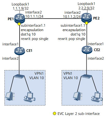
On the network shown in Figure 1, VPN1 services are sent to a VPWS network using the Ethernet technique. To enable users in VPN1 to communicate with each other, specify the pop traffic behavior on the PE so that the PE removes VLAN tags from packets before forwarding them to the VPWS network.
Configuration Roadmap
The configuration roadmap is as follows:
Configure Layer 2 forwarding on each CE.
- Create VLANs on each CE, add the interface connecting each CE to the user side to a VLAN, and assign each service to a specific VLAN.
- Configure Layer 2 forwarding on the interface connecting each CE to the network side so that a CE sends single-tagged packets to a PE.
Configure VPWS on each PE.
- Configure a routing protocol on PEs to ensure IP connectivity.
- Configure basic MPLS functions and MPLS LDP on PEs and establish MPLS LSPs.
- Enable MPLS L2VPN.
- Configure LDP VPWS on each PE.
- Configure an EVC model on each PE:
- Create a Layer 2 sub-interface and specify the traffic encapsulation type and behavior on the Layer 2 sub-interface.
- Configure VPWS on the EVC Layer 2 sub-interface.
Data Preparation
- User VLAN ID
- Numbers of interfaces that connect CEs to the user side and connect CEs to PEs
- Numbers and IP addresses of interfaces used by PEs to connect to each other
- MPLS LSR IDs of PEs
- Traffic encapsulation type and behavior
Procedure
- Configure Layer 2 forwarding on each CE.
# Configure CE1.
<HUAWEI> system-view
[~HUAWEI] sysname CE1
[*HUAWEI] commit
[~CE1] vlan 10
[*CE1-vlan10] quit
[*CE1] interface gigabitethernet 0/1/0
[*CE1-GigabitEthernet0/1/0] portswitch
[*CE1-GigabitEthernet0/1/0] port link-type trunk
[*CE1-GigabitEthernet0/1/0] port trunk allow-pass vlan 10
[*CE1-GigabitEthernet0/1/0] quit
[*CE1] interface gigabitethernet 0/1/8
[*CE1-GigabitEthernet0/1/8] portswitch
[*CE1-GigabitEthernet0/1/8] port link-type trunk
[*CE1-GigabitEthernet0/1/8] port trunk allow-pass vlan 10
[*CE1-GigabitEthernet0/1/8] quit
[*CE1] commit
# Configure CE2.
<HUAWEI> system-view
[~HUAWEI] sysname CE2
[*HUAWEI] commit
[~CE2] vlan 10
[*CE2-vlan10] quit
[*CE2] interface gigabitethernet 0/1/0
[*CE2-GigabitEthernet0/1/0] portswitch
[*CE2-GigabitEthernet0/1/0] port link-type trunk
[*CE2-GigabitEthernet0/1/0] port trunk allow-pass vlan 10
[*CE2-GigabitEthernet0/1/0] quit
[*CE2] interface gigabitethernet 0/1/8
[*CE2-GigabitEthernet0/1/8] portswitch
[*CE2-GigabitEthernet0/1/8] port link-type trunk
[*CE2-GigabitEthernet0/1/8] port trunk allow-pass vlan 10
[*CE2-GigabitEthernet0/1/8] quit
[*CE2] commit
- Establish the EVC model.
Create a Layer 2 sub-interface and specify the traffic encapsulation type and behavior on the Layer 2 sub-interface.
# Configure PE1.
<HUAWEI> system-view
[~HUAWEI] sysname PE1
[*HUAWEI] commit
[~PE1] interface gigabitethernet 0/1/0.1 mode l2
[*PE1-GigabitEthernet0/1/0.1] encapsulation dot1q vid 10
[*PE1-GigabitEthernet0/1/0.1] rewrite pop single
[*PE1-GigabitEthernet0/1/0.1] quit
[*PE1] commit
# Configure PE2.
<HUAWEI> system-view
[~HUAWEI] sysname PE2
[*HUAWEI] commit
[~PE2] interface gigabitethernet 0/1/0.1 mode l2
[*PE2-GigabitEthernet0/1/0.1] encapsulation dot1q vid 10
[*PE2-GigabitEthernet0/1/0.1] rewrite pop single
[*PE2-GigabitEthernet0/1/0.1] quit
[*PE2] commit
- Configure LDP VPWS.
Configure OSPF on each PE.
Assign an IP address to each PE interface. Ensure that the 32-bit loopback interface address of each PE is advertised after OSPF is enabled.
# Configure PE1.
[~PE1] interface loopback 1
[*PE1-LoopBack1] ip address 1.1.1.9 32
[*PE1-LoopBack1] quit
[*PE1] interface gigabitethernet 0/1/8
[*PE1-GigabitEthernet0/1/8] ip address 10.1.1.1 24
[*PE1-GigabitEthernet0/1/8] quit
[*PE1] ospf 1
[*PE1-ospf-1] area 0
[*PE1-ospf-1-area-0.0.0.0] network 1.1.1.9 0.0.0.0
[*PE1-ospf-1-area-0.0.0.0] network 10.1.1.0 0.0.0.255
[*PE1-ospf-1-area-0.0.0.0] quit
[*PE1-ospf-1] quit
[*PE1] commit
# Configure PE2.
[~PE2] interface loopback 1
[*PE2-LoopBack1] ip address 2.2.2.9 32
[*PE2-LoopBack1] quit
[*PE2] interface gigabitethernet 0/1/8
[*PE2-GigabitEthernet0/1/8] ip address 10.1.1.2 24
[*PE2-GigabitEthernet0/1/8] quit
[*PE2] ospf 1
[*PE2-ospf-1] area 0
[*PE2-ospf-1-area-0.0.0.0] network 2.2.2.9 0.0.0.0
[*PE2-ospf-1-area-0.0.0.0] network 10.1.1.0 0.0.0.255
[*PE2-ospf-1-area-0.0.0.0] quit
[*PE2-ospf-1] quit
[*PE2] commit
After completing the configuration, run the display ip routing-table command on each PE. The command output shows that OSPF-capable PE1 and PE2 have discovered routes to each other's loopback 1 interface and the two PEs can ping each other.
The following example uses the command output on PE1.
[~PE1] display ip routing-table
Route Flags: R - relay, D - download to fib, T - to vpn-instance, B - black hole route
------------------------------------------------------------------------------
Routing Table : _public_
         Destinations : 9        Routes : 9

Destination/Mask    Proto   Pre  Cost        Flags NextHop         Interface

        1.1.1.9/32  Direct  0    0             D  127.0.0.1       LoopBack1
        2.2.2.9/32  OSPF    10   1             D  10.1.1.2        GigabitEthernet0/1/8
       10.1.1.0/24  Direct  0    0             D  10.1.1.1        GigabitEthernet0/1/8
       10.1.1.1/32  Direct  0    0             D  127.0.0.1       GigabitEthernet0/1/8
     10.1.1.255/32  Direct  0    0             D  127.0.0.1       GigabitEthernet0/1/8
      127.0.0.0/8   Direct  0    0             D  127.0.0.1       InLoopBack0
      127.0.0.1/32  Direct  0    0             D  127.0.0.1       InLoopBack0
127.255.255.255/32  Direct  0    0             D  127.0.0.1       InLoopBack0
255.255.255.255/32  Direct  0    0             D  127.0.0.1       InLoopBack0
Configure basic MPLS functions and LDP.
# Configure PE1.
[~PE1] mpls lsr-id 1.1.1.9
[*PE1] mpls
[*PE1-mpls] quit
[*PE1] mpls ldp
[*PE1-mpls-ldp] quit
[*PE1] interface gigabitethernet 0/1/8
[*PE1-GigabitEthernet0/1/8] mpls
[*PE1-GigabitEthernet0/1/8] mpls ldp
[*PE1-GigabitEthernet0/1/8] quit
[*PE1] commit
# Configure PE2.
[~PE2] mpls lsr-id 2.2.2.9
[*PE2] mpls
[*PE2-mpls] quit
[*PE2] mpls ldp
[*PE2-mpls-ldp] quit
[*PE2] interface gigabitethernet 0/1/8
[*PE2-GigabitEthernet0/1/8] mpls
[*PE2-GigabitEthernet0/1/8] mpls ldp
[*PE2-GigabitEthernet0/1/8] quit
[*PE2] commit
After completing the preceding configuration, run the display mpls ldp session command on each PE. The command output shows that the LDP session is in the Operational state, indicating that the LDP session between PE1 and PE2 has been established.
[~PE1] display mpls ldp session
 LDP Session(s) in Public Network
 Codes: LAM(Label Advertisement Mode), SsnAge Unit(DDDD:HH:MM)
 An asterisk (*) before a session means the session is being deleted.
--------------------------------------------------------------------------
 PeerID             Status      LAM  SsnRole  SsnAge       KASent/Rcv
--------------------------------------------------------------------------
 2.2.2.9:0        Operational  DU   Passive  0000:00:00   1/1
--------------------------------------------------------------------------
TOTAL: 1 Session(s) Found.
If the PEs are indirectly connected, run the mpls ldp remote-peer and remote-ip commands to create a remote LDP session between the PEs.
Enable MPLS L2VPN.
# Configure PE1.
[~PE1] mpls l2vpn
[*PE1-l2vpn] quit
[*PE1] commit
# Configure PE2.
[~PE2] mpls l2vpn
[*PE2-l2vpn] quit
[*PE2] commit
Configure LDP VPWS.
# Configure PE1.
[~PE1] interface gigabitethernet 0/1/0.1
[*PE1-GigabitEthernet0/1/0.1] mpls l2vc 2.2.2.9 100 raw
[*PE1-GigabitEthernet0/1/0.1] quit
[*PE1] commit
# Configure PE2.
[~PE2] interface gigabitethernet 0/1/0.1
[*PE2-GigabitEthernet0/1/0.1] mpls l2vc 1.1.1.9 100 raw
[*PE2-GigabitEthernet0/1/0.1] quit
[*PE2] commit
- Verify the configuration.
Run the display ethernet uni information command. The command output shows the traffic encapsulation type and behavior configured on the Layer 2 sub-interface. The following example uses the command output on PE2.
[~PE2] display ethernet uni information
  GigabitEthernet0/1/0.1
    Total encapsulation number: 1
      encapsulation dot1q vid 10
    Rewrite pop single
Run the display mpls l2vc brief command. The command output shows that a VC has been established and is in the Up state. The following example uses the configuration on PE1.
[~PE1] display mpls l2vc brief
 Total LDP VC : 1     1 up       0 down

 *Client Interface  : GigabitEthernet0/1/1.1
  Administrator PW  : no
  AC status         : up
  VC state        : up
  Label state       : 0
  Token state       : 0
  VC ID             : 100
  VC Type           : Ethernet
  session state     : up
  Destination       : 2.2.2.9
  link state        : up
Configuration Files
PE1 configuration file
#
sysname PE1
#
vlan batch 10
#
mpls lsr-id 1.1.1.9
#
mpls
#
mpls l2vpn
#
mpls ldp
#
interface GigabitEthernet0/1/0
 undo shutdown
#
interface GigabitEthernet0/1/0.1 mode l2
 encapsulation dot1q vid 10
 rewrite pop single
 mpls l2vc 2.2.2.9 100 raw
#
interface GigabitEthernet0/1/8
 undo shutdown
 ip address 10.1.1.1 255.255.255.0
 mpls
 mpls ldp
#
ospf 1
 area 0.0.0.0
  network 1.1.1.9 0.0.0.0
  network 10.1.1.0 0.0.0.255
#
return
PE2 configuration file
#
sysname PE2
#
mpls lsr-id 2.2.2.9
#
mpls
#
mpls l2vpn
#
mpls ldp
#
interface GigabitEthernet0/1/0
 undo shutdown
#
interface GigabitEthernet0/1/0.1 mode l2
 encapsulation dot1q vid 10
 rewrite pop single
 mpls l2vc 1.1.1.9 100 raw
#
interface GigabitEthernet0/1/8
 undo shutdown
 ip address 10.1.1.2 255.255.255.0
 mpls
 mpls ldp
#
ospf 1
 area 0.0.0.0
  network 2.2.2.9 0.0.0.0
  network 10.1.1.0 0.0.0.255
#
return
CE1 configuration file
#
sysname CE1
#
vlan batch 10
#
interface GigabitEthernet0/1/0
 portswitch
undo shutdown
 port link-type trunk
port trunk allow-pass vlan 10
#
interface GigabitEthernet0/1/8
 portswitch
undo shutdown
 port link-type trunk
port trunk allow-pass vlan 10
#
return
CE2 configuration file
#
sysname CE2
#
vlan batch 10
#
interface GigabitEthernet0/1/0
 portswitch
undo shutdown
 port link-type trunk
port trunk allow-pass vlan 10
#
interface GigabitEthernet0/1/8
 portswitch
undo shutdown
 port link-type trunk
port trunk allow-pass vlan 10
#
return