Example for Configuring Interworking Between VLL and MPLS EVPN E-Line
Traditional VLL is still used at the aggregation layer of a network, whereas the core network has evolved to EVPN. To allow services to run properly network-wide, configure interworking between VLL and MPLS EVPN E-Line.
Networking Requirements
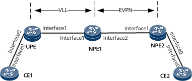
On the network shown in Figure 1, VLL (or VPWS) is deployed between the UPE and NPE1, and EVPN is deployed between NPE1 and NPE2. A PW-VE interface and its sub-interface are configured on NPE1 to implement VLL accessing EVPN. VLL configurations are performed on the PW-VE interface, and EVPN configurations are performed on the PW-VE sub-interface. Specifically, an EVPL instance corresponding to the EVPN instance is bound to the PW-VE sub-interface, and the QinQ encapsulation type is configured on the sub-interface.

Interfaces 0 through 2 in this example represent GE0/1/0, GE0/1/1, and GE0/1/2, respectively.
Device |
Interface |
IP Address and Mask |
|---|---|---|
NPE1 |
GigabitEthernet 0/1/1 |
10.1.1.1/24 |
GigabitEthernet 0/1/2 |
192.168.14.1/24 |
|
Loopback 0 |
10.10.10.1/32 |
|
Loopback 100 |
10.10.10.100/32 |
|
UPE |
GigabitEthernet 0/1/0 |
- |
GigabitEthernet 0/1/1 |
10.1.1.3/24 |
|
Loopback 0 |
10.10.10.2/32 |
|
NPE2 |
GigabitEthernet 0/1/0 |
- |
GigabitEthernet 0/1/1 |
192.168.14.4/24 |
|
Loopback 100 |
10.10.20.100/32 |
Configuration Roadmap
The configuration roadmap is as follows:
Configure an IGP on each device. Because the VLL network (between the UPE and NPE1) and EVPN network (between NPE1 and NPE2) reside at different layers, different IGP processes are used for route reachability in this case.
Configure basic MPLS LDP functions on the UPE, NPE1, and NPE2.
Configure VPWS connections on the UPE and NPE1.
Configure EVPN functions on NPE1 and NPE2, including creating EVPN instances and establishing a BGP EVPN peer relationship between the devices.
Configure EVPL functions on NPE1 and NPE2.
On NPE1, bind VLL to the PW-VE interface, and bind the EVPL instance to the PE-VE sub-interface.
Data Preparation
To complete the configuration, you need the following data:
Interface names and IP addresses of the interfaces on NPE1, NPE2, and the UPE
MPLS LSR IDs on the UPE, NPE1, and NPE2
Names, RDs, and VPN targets of the EVPN instances on NPE1 and NPE2
Procedure
- Configure interface addresses and an IGP on NPE1, NPE2, and the UPE. In this example, OSPF is used as the IGP.
For configuration details, see Configuration Files in this section.
- Configure basic MPLS functions and MPLS LDP on NPE1, NPE2, and the UPE.
For configuration details, see Configuration Files in this section.
- Configure VPWS connections on the UPE and NPE1.
For configuration details, see Configuration Files in this section.
- Configure EVPN functions on NPE1 and NPE2, including creating EVPN instances and establishing a BGP EVPN peer relationship between the devices.
# Configure NPE1.
[~NPE1] evpn vpn-instance evpna vpws
[*NPE1-vpws-evpn-instance-evpna] route-distinguisher 1:1
[*NPE1-vpws-evpn-instance-evpna] vpn-target 10:10 export-extcommunity
[*NPE1-vpws-evpn-instance-evpna] vpn-target 10:10 import-extcommunity
[*NPE1-vpws-evpn-instance-evpna] quit
[*NPE1] bgp 100
[*NPE1-bgp] peer 10.10.20.100 as-number 100
[*NPE1-bgp] peer 10.10.20.100 connect-interface LoopBack100
[*NPE1-bgp] l2vpn-family evpn
[*NPE1-bgp-af-evpn] peer 10.10.20.100 enable
[*NPE1-bgp-af-evpn] quit
[*NPE1-bgp] quit
[*NPE1] commit
The configuration on NPE2 is similar to that on NPE1. For configuration details, see Configuration Files in this section.
- Configure EVPL functions on NPE1 and NPE2.
# Configure NPE1.
[~NPE1] evpl instance 1
[*NPE1-evpl1] evpn binding vpn-instance evpna
[*NPE1-evpl1] local-service-id 100 remote-service-id 200
[*NPE1-evpl1] quit
[*NPE1] commit
The configuration on NPE2 is similar to that on NPE1. For configuration details, see Configuration Files in this section.
- On NPE1, bind VLL to the PW-VE interface and the EVPN instance to the PW-VE sub-interface.
# Configure NPE1.
[~NPE1] mpls
[*NPE1-mpls] mpls l2vpn
[*NPE1-l2vpn] quit
[*NPE1] interface PW-VE 1
[*NPE1-PW-VE1] esi 0011.1111.0000.0000.0000
[*NPE1-PW-VE1] mpls l2vc 10.10.10.2 1
[*NPE1-PW-VE1] quit
[*NPE1] interface PW-VE 1.1
[*NPE1-PW-VE1.1] encapsulation qinq-termination
[*NPE1-PW-VE1.1] qinq termination pe-vid 100 ce-vid 100
[*NPE1-PW-VE1.1] evpl instance 1
[*NPE1-PW-VE1.1] commit
- Verify the configuration.
Run the display bgp evpn all routing-table command on NPE2. The command output shows the per-EVI A-D routes sent by NPE1.
[~NPE2] display bgp evpn all routing-table
 Local AS number : 100

 BGP Local router ID is 192.168.14.4
 Status codes: * - valid, > - best, d - damped, x - best external, a - add path,
               h - history,  i - internal, s - suppressed, S - Stale
               Origin : i - IGP, e - EGP, ? - incomplete


 EVPN address family:
 Number of A-D Routes: 4
 Route Distinguisher: 1:1
       Network(ESI/EthTagId)                                  NextHop
 *>i   0011.1111.0000.0000.0000:100                        10.10.10.100
 Route Distinguisher: 10.10.10.100:0
       Network(ESI/EthTagId)                                  NextHop
 *>i   0011.1111.0000.0000.0000:4294967295                    10.10.10.100
 Route Distinguisher: 10.10.20.100:0
       Network(ESI/EthTagId)                                  NextHop
 *>    0011.1111.0000.0000.1111:4294967295                    127.0.0.1
 Route Distinguisher: 10.10.20.100:10
       Network(ESI/EthTagId)                                  NextHop
 *>    0011.1111.0000.0000.1111:200                           127.0.0.1


 EVPN-Instance evpna:
 Number of A-D Routes: 3
       Network(ESI/EthTagId)                                  NextHop
 *>i   0011.1111.0000.0000.0000:100                        10.10.10.100
 *>i   0011.1111.0000.0000.0000:4294967295                    10.10.10.100
 *>    0011.1111.0000.0000.1111:200                        127.0.0.1

 EVPN address family:
 Number of ES Routes: 2
 Route Distinguisher: 10.10.10.100:0
       Network(ESI)                                           NextHop
 *>i   0011.1111.0000.0000.0000                               10.10.10.100
 Route Distinguisher: 10.10.20.100:0
       Network(ESI)                                           NextHop
 *>    0011.1111.0000.0000.1111                               127.0.0.1


 EVPN-Instance evpna:
 Number of ES Routes: 1
       Network(ESI)                                           NextHop
 *>    0011.1111.0000.0000.1111                               127.0.0.1
Configuration Files
- NPE1 configuration file
#
sysname NPE1
#
evpn vpn-instance evpna vpws
 route-distinguisher 1:1
 vpn-target 10:10 export-extcommunity
 vpn-target 10:10 import-extcommunity
#
evpl instance 1
 evpn binding vpn-instance evpna
 local-service-id 100 remote-service-id 200
#
mpls lsr-id 10.10.10.1
#
mpls
#
mpls l2vpn
#
mpls ldp
#
interface GigabitEthernet0/1/1
 undo shutdown
 ip address 10.1.1.1 255.255.255.0
 mpls
 mpls ldp
#
interface GigabitEthernet0/1/2
 undo shutdown
 ip address 192.168.14.1 255.255.255.0
 mpls
 mpls ldp
 mpls ldp local-lsr-id LoopBack100
#
interface LoopBack0
 ip address 10.10.10.1 255.255.255.255
#
interface LoopBack100
 ip address 10.10.10.100 255.255.255.255
#
interface PW-VE1
 esi 0011.1111.0000.0000.0000
 mpls l2vc 10.10.10.2 1
#
interface PW-VE1.1
 encapsulation qinq-termination
 qinq termination pe-vid 100 ce-vid 100
 evpl instance 1
#
bgp 100
 peer 10.10.20.100 as-number 100
 peer 10.10.20.100 connect-interface LoopBack100
 #
 ipv4-family unicast
  undo synchronization
  peer 10.10.20.100 enable
 #
 l2vpn-family evpn
  undo policy vpn-target
  peer 10.10.20.100 enable
#
ospf 1
 area 0.0.0.0
  network 10.10.10.1 0.0.0.0
  network 10.1.1.0 0.0.0.255
#
ospf 100
 area 0.0.0.1
  network 10.10.10.100 0.0.0.0
  network 192.168.14.0 0.0.0.255
#
evpn source-address 10.10.10.100
#
return
UPE configuration file
#
sysname UPE
#
mpls lsr-id 10.10.10.2
#
mpls
#
mpls l2vpn
#
mpls ldp
#
interface GigabitEthernet0/1/0
 undo shutdown
 mpls l2vc 10.10.10.1 1
#
interface GigabitEthernet0/1/1
 undo shutdown
 ip address 10.1.1.3 255.255.255.0
 mpls
 mpls ldp
#
interface LoopBack0
 ip address 10.10.10.2 255.255.255.255
#
ospf 1
 area 0.0.0.0
  network 10.10.10.2 0.0.0.0
  network 10.1.1.0 0.0.0.255
#
return
NPE2 configuration file
#
sysname NPE2
#
evpn vpn-instance evpna vpws
 route-distinguisher 10.10.20.100:10
 vpn-target 10:10 export-extcommunity
 vpn-target 10:10 import-extcommunity
#
evpl instance 1
 evpn binding vpn-instance evpna
 local-service-id 200 remote-service-id 100
#
mpls lsr-id 10.10.20.100
#
mpls
#
mpls l2vpn
#
mpls ldp
#
interface GigabitEthernet0/1/0
 undo shutdown
 esi 0011.1111.0000.0000.1111
#
interface GigabitEthernet0/1/0.1 mode l2
 encapsulation qinq vid 100 ce-vid 100
 rewrite pop double
 evpl instance 1
#
interface GigabitEthernet0/1/1
 undo shutdown
 ip address 192.168.14.4 255.255.255.0
 mpls
 mpls ldp
#
interface LoopBack100
 ip address 10.10.20.100 255.255.255.255
#
bgp 100
 peer 10.10.10.100 as-number 100
 peer 10.10.10.100 connect-interface LoopBack100
 #
 ipv4-family unicast
  undo synchronization
  peer 10.10.10.100 enable
 #
 l2vpn-family evpn
  undo policy vpn-target
  peer 10.10.10.100 enable
#
ospf 100
 area 0.0.0.1
  network 10.10.20.100 0.0.0.0
  network 192.168.14.0 0.0.0.255
#
evpn source-address 10.10.20.100
#
return
- CE1 configuration file
#
sysname CE1
#
bridge-domain 10
#
interface Vbdif10
 ip address 192.168.1.11 255.255.255.0
#
interface GigabitEthernet0/1/0
 undo shutdown
#
interface GigabitEthernet0/1/0.1 mode l2
 encapsulation qinq vid 100 ce-vid 100
 rewrite pop double
 bridge-domain 10
#
return
- CE2 configuration file
#
sysname CE2
#
bridge-domain 10
#
interface Vbdif10
 ip address 192.168.1.12 255.255.255.0
#
interface GigabitEthernet0/1/0
 undo shutdown
#
interface GigabitEthernet0/1/0.1 mode l2
 encapsulation qinq vid 100 ce-vid 100
 rewrite pop double
 bridge-domain 10
#
return