Example for Configuring Interworking Between a VLL and a Common EVPN E-LAN
Traditional VLL is still used at the aggregation layer of a network, whereas the core network has evolved into EVPN. To allow communication between different layers, VLL accessing EVPN must be configured. This section provides an example for configuring this function.
Networking Requirements
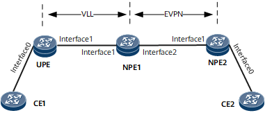
On the network shown in the following figure, a VLL (or VPWS) network is deployed between the UPE and NPE1, and an EVPN is deployed between NPE1 and NPE2. To implement VLL accessing EVPN, a PW-VE interface and its sub-interface must be configured on NPE1. Specifically, the VLL configurations are performed on the PW-VE interface, and the EVPN configurations are performed on the PW-VE sub-interface. The PW-VE sub-interface is configured as a QinQ VLAN tag termination sub-interface.

Interfaces 0 through 2 in this example represent GigabitEthernet 0/1/0, GigabitEthernet 0/1/1 , and GigabitEthernet 0/1/2, respectively.
Device Name |
Interface Name |
IP Address and Mask |
|---|---|---|
NPE1 |
GigabitEthernet 0/1/1 |
10.1.1.1/24 |
GigabitEthernet 0/1/2 |
192.168.14.1/24 |
|
Loopback 0 |
1.1.1.1/32 |
|
Loopback 100 |
1.1.1.100/32 |
|
UPE |
GigabitEthernet 0/1/0 |
- |
GigabitEthernet 0/1/1 |
10.1.1.3/24 |
|
Loopback 0 |
2.2.2.2/32 |
|
NPE2 |
GigabitEthernet 0/1/0 |
- |
GigabitEthernet 0/1/1 |
192.168.14.4/24 |
|
Loopback 100 |
2.2.2.100/32 |
Configuration Roadmap
The configuration roadmap is as follows:
Configure an IGP on each device. Because the VLL network (between the UPE and NPE1) and EVPN (between NPE1 and NPE2) reside at different layers, use different IGP processes to implement route communication.
Configure basic MPLS functions on the UPE, NPE1, and NPE2.
Configure VPWS connections on the UPE and NPE1.
Configure EVPN functions on NPE1 and NPE2 and establish an MPLS tunnel between them.
On NPE1, bind the VSI to the PW-VE interface and the EVPN instance to PE-VE sub-interface.
Data Preparation
To complete the configuration, you need the following data:
Interface names and IP addresses of the interfaces on NPE1, NPE2, and the UPE
MPLS LSR IDs on the UPE, NPE1, and NPE2
Names, RDs, and VPN targets of the EVPN instances created on NPE1 and NPE2
Procedure
- Configure IP addresses for interfaces on the UPE, NPE1, and NPE2 and configure an IGP. OSPF is used in this example.
For configuration details, see "Configuration Files" in this section.
- Configure basic MPLS functions and MPLS LDP on the UPE and NPE1.
For detailed configurations, see "Configuration Files" in this section.
- Configure VPWS connections on the UPE and NPE1.
For detailed configurations, see "Configuration Files" in this section.
- Configure basic EVPN functions on NPE2.
For detailed configurations, see "Configuration Files" in this section.
- Configure BGP on NPE1 and NPE2 and establish an EVPN peer relationship between them.
For detailed configurations, see "Configuration Files" in this section.
- Configure an EVPN instance on NPE1.
# Configure NPE1.
[~NPE1] evpn vpn-instance evpna
[*NPE1-evpn-instance-evpna] route-distinguisher 1.1.1.100:10
[*NPE1-evpn-instance-evpna] vpn-target 10:10 export-extcommunity
[*NPE1-evpn-instance-evpna] vpn-target 10:10 import-extcommunity
[*NPE1-evpn-instance-evpna] quit
[*NPE1] evpn source-address 1.1.1.100
[*NPE1] commit
- Configure a PW on the UPE that connects to NPE1.
[~UPE] interface GigabitEthernet 0/1/0
[~UPE-GigabitEthernet0/1/0] mpls l2vc 1.1.1.1 1
[*UPE-GigabitEthernet0/1/0] quit
[*UPE] commit
- On NPE1, bind the VSI to the PW-VE interface and the EVPN instance to the PW-VE sub-interface.
# Configure NPE1.
[~NPE1] mpls
[*NPE1-mpls] mpls l2vpn
[*NPE1-mpls] quit
[*NPE1] interface PW-VE 1
[*NPE1-PW-VE1] mpls l2vc 2.2.2.2 1
[*NPE1-PW-VE1] quit
[*NPE1] interface PW-VE 1.1
[*NPE1-PW-VE1.1] encapsulation qinq-termination
[*NPE1-PW-VE1.1] qinq termination pe-vid 100 ce-vid 1 to 2
[*NPE1-PW-VE1.1] evpn binding vpn-instance evpna
[*NPE1-PW-VE1.1] commit
- Verify the configuration.
Run display mpls l2vc, the PW-VE1 interface and LDP VC were UP.
[~NPE1] display mpls l2vc
 Total LDP VC : 1     1 up       0 down

 *client interface       : PW-VE1 is up
  Administrator PW       : no
  session state          : up
  AC status              : up
  Ignore AC state        : disable
  VC state               : up
  Label state            : 0
  Token state            : 0
  VC ID                  : 2
  VC type                : Ethernet
  destination            : 2.2.2.2
  local VC label         : 33053        remote VC label      : 0
  control word           : disable
  remote control word    : none
  forwarding entry       : not exist
  local group ID         : 0
  remote group ID        : 0
  local AC OAM State     : up
  local PSN OAM State    : up
  local forwarding state : forwarding
  local status code      : 0x0
  BFD for PW             : unavailable
  VCCV State             : up
  manual fault           : not set
  active state           : inactive
  OAM Protocol           : --
  OAM Status             : --
  OAM Fault Type         : --
  PW APS ID              : --
  PW APS Status          : --
  TTL Value              : 1
  link state             : down
  local VC MTU           : 1500         remote VC MTU        : 0
  local VCCV             : alert ttl lsp-ping bfd
  remote VCCV            : none
  tunnel policy name     : --
  PW template name       : --
  primary or secondary   : primary
  load balance type      : flow
  Access-port            : false
  Switchover Flag        : false
  VC tunnel info         : 1 tunnels
    NO.0  TNL type       : ldp            , TNL ID : 0x0000000001004c4bc1
  create time                  : 0 days, 0 hours, 17 minutes, 58 seconds
  up time                      : 0 days, 0 hours, 16 minutes, 50 seconds
  last change time             : 0 days, 0 hours, 16 minutes, 50 seconds
  VC last up time              : 2018/02/05 02:50:41
  VC total up time             : 0 days, 0 hours, 16 minutes, 50 seconds
  CKey                   : 577
  NKey                   : 16777487
  PW redundancy mode     : frr
  AdminPw interface      : --
  AdminPw link state     : --
  Forward state          : send inactive, receive inactive
  Diffserv Mode          : uniform
  Service Class          : --
  Color                  : --
  DomainId               : --
  Domain Name            : --
Configuration Files
- NPE1 configuration file
#
sysname NPE1
#
evpn vpn-instance evpna
 route-distinguisher 1.1.1.100:10
 vpn-target 10:10 export-extcommunity
 vpn-target 10:10 import-extcommunity
#
mpls lsr-id 1.1.1.1
#
mpls
#
mpls l2vpn
#
mpls ldp
#
interface GigabitEthernet0/1/1
 undo shutdown
 ip address 10.1.1.1 255.255.255.0
 mpls
 mpls ldp
#
interface GigabitEthernet0/1/2
 undo shutdown
 ip address 192.168.14.1 255.255.255.0
 mpls
 mpls ldp
#
interface LoopBack0
 ip address 1.1.1.1 255.255.255.255
#
interface LoopBack100
 ip address 1.1.1.100 255.255.255.255
#
interface PW-VE1
 mpls l2vc 2.2.2.2 1
#
interface PW-VE1.1
 encapsulation qinq-termination
 qinq termination pe-vid 100 ce-vid 1 to 2
 evpn binding vpn-instance evpna
#
bgp 100
 peer 2.2.2.100 as-number 65001
 peer 2.2.2.100 ebgp-max-hop 255
 peer 2.2.2.100 connect-interface LoopBack100
 #
 ipv4-family unicast
  undo synchronization
  peer 2.2.2.100 enable
 #
 l2vpn-family evpn
  undo policy vpn-target
  peer 2.2.2.100 enable
#
ospf 1
 area 0.0.0.0
  network 1.1.1.1  0.0.0.0
  network 10.1.1.0 0.0.0.255
#
ospf 100
 area 0.0.0.1
  network 1.1.1.100 0.0.0.0
  network 192.168.14.0 0.0.0.255
#
evpn source-address 1.1.1.100
#
return
UPE configuration file
#
sysname UPE
#
mpls lsr-id 2.2.2.2
#
mpls
#
mpls l2vpn
#
mpls ldp
#
interface GigabitEthernet0/1/0
 undo shutdown
 mpls l2vc 1.1.1.1 1
#
interface GigabitEthernet0/1/1
 undo shutdown
 ip address 10.1.1.3 255.255.255.0
 mpls
 mpls ldp
#
interface LoopBack0
 ip address 2.2.2.2 255.255.255.255
#
ospf 1
 area 0.0.0.0
  network 2.2.2.2 0.0.0.0
  network 10.1.1.0 0.0.0.255
#
return
NPE2 configuration file
#
sysname NPE2
#
evpn vpn-instance evpna
 route-distinguisher 2.2.2.100:10
 vpn-target 10:10 export-extcommunity
 vpn-target 10:10 import-extcommunity
#
mpls lsr-id 2.2.2.100
#
mpls
#
mpls l2vpn
#
mpls ldp
#
interface GigabitEthernet0/1/0
 undo shutdown
 evpn binding vpn-instance evpna
#
interface GigabitEthernet0/1/1
 undo portswitch
 ip address 192.168.14.4 255.255.255.0
 mpls
 mpls ldp
#
interface LoopBack100
 ip address 2.2.2.100 255.255.255.255
#
bgp 65001
 peer 1.1.1.100 as-number 100
 peer 1.1.1.100 ebgp-max-hop 255
 peer 1.1.1.100 connect-interface LoopBack100
 #
 ipv4-family unicast
  undo synchronization
  peer 1.1.1.100 enable
 #
 l2vpn-family evpn
  undo policy vpn-target
  peer 1.1.1.100 enable
#
ospf 100
 area 0.0.0.1
  network 2.2.2.100 0.0.0.0
  network 192.168.14.0 0.0.0.255
#
evpn source-address 2.2.2.100
#
return