Example for Configuring NS Multicast Suppression on an EVPN MPLS Network
This section provides an example for configuring NS multicast suppression on an EVPN MPLS network to reduce or suppress excess NS messages on the network.
Networking Requirements
When a user is connected to an EVPN MPLS network through a BD, IPv6 host neighbors are discovered in NS multicast mode. When a device receives an NS message for IPv6 address resolution, the device forwards the NS message in multicast mode in its BD. If a large number of NS messages are received within a specified period, forwarding all these NS messages on the EVPN occupies excessive network resources, which affects service running.
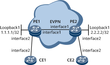
On the network shown in Figure 1, NS multicast suppression can be configured on a PE. When receiving an NS message, the PE checks whether it can obtain the destination user information in the NS message. If so, it performs proxy ND or multicast-to-unicast processing to reduce or suppress NS message flooding. NS multicast suppression can also prevent ND spoofing attacks. During ND spoofing attacks, an attacker associates its MAC address with the IPv6 address of a host so that all traffic destined for the IPv6 address is sent to the attacker. After NS multicast suppression is enabled, an IPv6 address conflict alarm will be generated through proxy ND entry conflict detection to notify users of a possible ND spoofing attack.

Configuration Roadmap
The configuration roadmap is as follows:
Configure basic EVPN functions.
Enable NS multicast suppression.
Enable the function to flood proxy ND entries through EVPN routes.
Configure the CEs and PEs to communicate.
Data Preparation
To complete the configuration, you need the following data:
EVPN instance name: evpna
RD of the EVPN instance on a PE: 3:3
Procedure
- Configure basic EVPN functions.
Configure interface IP addresses.
# Configure PE1.
<HUAWEI> system-view
[~HUAWEI] sysname PE1
[*HUAWEI] commit
[~PE1] interface gigabitethernet 0/1/0
[~PE1-GigabitEthernet0/1/0] ip address 10.0.0.1 255.255.255.0
[*PE1-GigabitEthernet0/1/0] commit
[~PE1-GigabitEthernet0/1/0] quit
[~PE1] interface loopback 0
[*PE1-LoopBack0] ip address 1.1.1.1 255.255.255.255
[*PE1-LoopBack0] commit
[~PE1-LoopBack0] quit
The configuration of PE2 is similar to the configuration of PE1. For configuration details, see Configuration Files in this section.
Configure an IGP to implement interworking between the PEs. OSPF is used in this example.
# Configure PE1.
[~PE1] ospf 1
[*PE1-ospf-1] area 0
[*PE1-ospf-1-area-0.0.0.0] network 1.1.1.1 0.0.0.0
[*PE1-ospf-1-area-0.0.0.0] network 10.0.0.0 0.0.0.255
[*PE1-ospf-1-area-0.0.0.0] commit
[~PE1-ospf-1-area-0.0.0.0] quit
[~PE1-ospf-1] quit
The configuration of PE2 is similar to the configuration of PE1. For configuration details, see Configuration Files in this section.
After the configuration is complete, run the display ospf peer command. The command output shows that an OSPF neighbor relationship has been set up between PE1 and PE2 and its state is Full. Run the display ip routing-table command. The command output shows that PE1 and PE2 have learned the routes to each other's Loopback1.
The following example uses the command output on PE1.
[~PE1] display ospf peer
(M) Indicates MADJ neighbor


          OSPF Process 1 with Router ID 1.1.1.1
                Neighbors

 Area 0.0.0.0 interface 10.0.0.1 (GE0/1/0)'s neighbors
 Router ID: 2.2.2.2              Address: 10.0.0.2
   State: Full           Mode:Nbr is Master     Priority: 1
   DR: 10.0.0.1          BDR: 10.0.0.2          MTU: 0
   Dead timer due in  38  sec
   Retrans timer interval: 5
   Neighbor is up for 01h54m10s
   Authentication Sequence: [ 0 ]
[~PE1] display ip routing-table
Route Flags: R - relay, D - download to fib, T - to vpn-instance, B - black hole route
------------------------------------------------------------------------------
Routing Table : _public_
         Destinations : 9        Routes : 9

Destination/Mask    Proto   Pre  Cost        Flags NextHop         Interface

        1.1.1.1/32  Direct  0    0             D   127.0.0.1       LoopBack0
        2.2.2.2/32  OSPF    10   1             D   10.0.0.2        GigabitEthernet0/1/0
       10.0.0.0/24  Direct  0    0             D   10.0.0.1        GigabitEthernet0/1/0
       10.0.0.1/32  Direct  0    0             D   127.0.0.1       GigabitEthernet0/1/0
     10.0.0.255/32  Direct  0    0             D   127.0.0.1       GigabitEthernet0/1/0
      127.0.0.0/8   Direct  0    0             D   127.0.0.1       InLoopBack0
      127.0.0.1/32  Direct  0    0             D   127.0.0.1       InLoopBack0
127.255.255.255/32  Direct  0    0             D   127.0.0.1       InLoopBack0
255.255.255.255/32  Direct  0    0             D   127.0.0.1       InLoopBack0
Configure basic MPLS functions and MPLS LDP, and set up LDP LSPs.
# Configure PE1.
[~PE1] mpls lsr-id 1.1.1.1
[*PE1] mpls
[*PE1-mpls] mpls ldp
[*PE1-mpls] commit
[~PE1-mpls] quit
[~PE1] interface gigabitethernet 0/1/0
[~PE1-GigabitEthernet0/1/0] mpls
[*PE1-GigabitEthernet0/1/0] mpls ldp
[*PE1-GigabitEthernet0/1/0] commit
[~PE1-GigabitEthernet0/1/0] quit
The configuration of PE2 is similar to the configuration of PE1. For configuration details, see Configuration Files in this section.
After the configuration is complete, run the display mpls ldp session command. The command output shows that an LDP session has been set up between PE1 and PE2 and its state is Operational. Run the display mpls ldp lsp command. The command output shows information about LDP LSP setup.
The following example uses the command output on PE1.
[~PE1] display mpls ldp session
LDP Session(s) in Public Network
 Codes: LAM(Label Advertisement Mode), SsnAge Unit(DDDD:HH:MM)
 An asterisk (*) before a session means the session is being deleted.
 --------------------------------------------------------------------------
 PeerID             Status      LAM  SsnRole  SsnAge       KASent/Rcv
 --------------------------------------------------------------------------
 2.2.2.2:0          Operational DU   Passive  0000:02:03   494/494
 --------------------------------------------------------------------------
 TOTAL: 1 Session(s) Found.
[~PE1] display mpls ldp lsp
 LDP LSP Information
 -------------------------------------------------------------------------------
 Flag after Out IF: (I) - RLFA Iterated LSP, (I*) - Normal and RLFA Iterated LSP
 -------------------------------------------------------------------------------
 DestAddress/Mask   In/OutLabel    UpstreamPeer    NextHop          OutInterface
 -------------------------------------------------------------------------------
 1.1.1.1/32         3/NULL         2.2.2.2         127.0.0.1        Loop0
*1.1.1.1/32         Liberal/32967                  DS/2.2.2.2
 2.2.2.2/32         NULL/3         -               10.0.0.2         GE0/1/0
 2.2.2.2/32         32967/3        2.2.2.2         10.0.0.2         GE0/1/0
 -------------------------------------------------------------------------------
 TOTAL: 3 Normal LSP(s) Found.
 TOTAL: 1 Liberal LSP(s) Found.
 TOTAL: 0 FRR LSP(s) Found.
 An asterisk (*) before an LSP means the LSP is not established
 An asterisk (*) before a Label means the USCB or DSCB is stale
 An asterisk (*) before an UpstreamPeer means the session is stale
 An asterisk (*) before a DS means the session is stale
 An asterisk (*) before a NextHop means the LSP is FRR LSP
Configure EVPN instances.
# Configure PE1.
[~PE1] evpn vpn-instance evpna bd-mode
[*PE1-evpn-instance-evpna] route-distinguisher 3:3
[*PE1-evpn-instance-evpna] vpn-target 1:1
[*PE1-evpn-instance-evpna] commit
[~PE1-evpn-instance-evpna] quit
The configuration of PE2 is similar to the configuration of PE1. For configuration details, see Configuration Files in this section.
Configure EVPN source addresses.
# Configure PE1.
[~PE1] evpn source-address 1.1.1.1
[*PE1] commit
The configuration of PE2 is similar to the configuration of PE1. For configuration details, see Configuration Files in this section.
Bind an EVPN instance to a BD.
# Configure PE1.
[~PE1] bridge-domain 10
[*PE1-bd10] evpn binding vpn-instance evpna
[*PE1-bd10] commit
[~PE1-bd10] quit
The configuration of PE2 is similar to the configuration of PE1. For configuration details, see Configuration Files in this section.
Configure a BGP EVPN peer relationship.
# Configure PE1.
[~PE1] bgp 100
[*PE1-bgp] peer 2.2.2.2 as-number 100
[*PE1-bgp] peer 2.2.2.2 connect-interface LoopBack 0
[*PE1-bgp] l2vpn-family evpn
[*PE1-bgp-af-evpn] peer 2.2.2.2 enable
[*PE1-bgp-af-evpn] peer 2.2.2.2 advertise nd
[*PE1-bgp-af-evpn] commit
[~PE1-bgp-af-evpn] quit
[~PE1-bgp] quit
The configuration of PE2 is similar to the configuration of PE1. For configuration details, see Configuration Files in this section.
- Enable NS multicast suppression.
# Configure PE1.
[~PE1] bridge-domain 10
[~PE1-bd10] ipv6 nd multicast-suppress proxy-reply enable
The configuration of PE2 is similar to the configuration of PE1. For configuration details, see Configuration Files in this section.
- Enable the function to flood proxy ND entries through EVPN routes.
# Configure PE1.
[*PE1-bd10] ipv6 nd collect host enable
[*PE1-bd10] commit
[~PE1-bd10] quit
The configuration of PE2 is similar to the configuration of PE1. For configuration details, see Configuration Files in this section.
- Configure the CEs and PEs to communicate.
# Configure PE1.
[~PE1] interface gigabitethernet 0/1/8.1 mode l2
[*PE1-GigabitEthernet0/1/8.1] encapsulation dot1q vid 1
[*PE1-GigabitEthernet0/1/8.1] rewrite pop single
[*PE1-GigabitEthernet0/1/8.1] bridge-domain 10
[*PE1-GigabitEthernet0/1/8.1] commit
[~PE1-GigabitEthernet0/1/8.1] quit
The configuration of PE2 is similar to the configuration of PE1. For configuration details, see Configuration Files in this section.
# Configure CE1.
<HUAWEI> system-view
[~HUAWEI] sysname CE1
[*HUAWEI] commit
[~CE1] interface gigabitethernet 0/1/8.1
[*CE1-GigabitEthernet0/1/8.1] ipv6 enable
[*CE1-GigabitEthernet0/1/8.1] ipv6 address 2001:db8::1 64
[*CE1-GigabitEthernet0/1/8.1] vlan-type dot1q 1
[*CE1-GigabitEthernet0/1/8.1] commit
[~CE1-GigabitEthernet0/1/8.1] quit
The configuration of CE2 is similar to the configuration of CE1. For configuration details, see Configuration Files in this section.
- Verify the configuration.
Run the display bgp evpn all routing-table mac-route command on PE1. The command output shows MAC/IP advertisement routes to PE2.
[~PE1] display bgp evpn all routing-table mac-route
 Local AS number : 100

 BGP Local router ID is 1.1.1.1
 Status codes: * - valid, > - best, d - damped, x - best external, a - add path,
               h - history,  i - internal, s - suppressed, S - Stale
               Origin : i - IGP, e - EGP, ? - incomplete


 EVPN address family:
 Number of Mac Routes: 6
 Route Distinguisher: 3:3
       Network(EthTagId/MacAddrLen/MacAddr/IpAddrLen/IpAddr)  NextHop
 *>    0:48:00e0-fc12-3456:0:0.0.0.0                          0.0.0.0
 *>i   0:48:00e0-fc12-7890:0:0.0.0.0                          2.2.2.2
 *>    0:48:00e0-fc12-3456:128:[FE80::3A00:10FF:FE03:0]       0.0.0.0
 *>    0:48:00e0-fc12-3456:128:[2001:DB8::1]                  0.0.0.0
 *>i   0:48:00e0-fc12-7890:128:[FE80::3ABD:6CFF:FE31:300]     2.2.2.2
 *>i   0:48:00e0-fc12-7890:128:[2001:DB8::2]                  2.2.2.2


 EVPN-Instance evpna:
 Number of Mac Routes: 6
       Network(EthTagId/MacAddrLen/MacAddr/IpAddrLen/IpAddr)  NextHop
 *>    0:48:00e0-fc12-3456:0:0.0.0.0                          0.0.0.0
 *>i   0:48:00e0-fc12-7890:0:0.0.0.0                          2.2.2.2
 *>    0:48:00e0-fc12-3456:128:[FE80::3A00:10FF:FE03:0]       0.0.0.0
 *>    0:48:00e0-fc12-3456:128:[2001:DB8::1]                  0.0.0.0
 *>i   0:48:00e0-fc12-7890:128:[FE80::3ABD:6CFF:FE31:300]     2.2.2.2
 *>i   0:48:00e0-fc12-7890:128:[2001:DB8::2]                  2.2.2.2
Run the display ipv6 nd multicast-suppress bridge-domain command on PE1. The command output shows that the proxy ND table contains entries of CE1 and CE2. The 2001:db8::1 entry is a dynamic proxy ND entry generated by the local device, and the 2001:db8::2 entry is a proxy ND entry pushed by the remote device.
[~PE1] display ipv6 nd multicast-suppress bridge-domain
----------------------------------------------------------------------------------
IPv6 Address
MAC Address            BD         LifeTime (S)      Type
----------------------------------------------------------------------------------
2001:DB8::1
00e0-fc12-3456         10         76                Dynamic

2001:DB8::2
00e0-fc12-7890         10         -                 Evpn

FE80::3A00:10FF:FE03:0
00e0-fc12-3456         10         75                Dynamic

FE80::3ABD:6CFF:FE31:300
00e0-fc12-7890         10         -                 Evpn

----------------------------------------------------------------------------------
Total: 4        Dynamic: 2      Evpn: 2
Run the display ipv6 nd multicast-suppress bridge-domain command on PE2. The command output shows that the proxy ND table contains entries of CE1 and CE2. The 2001:db8::2 entry is a dynamic proxy ND entry generated by the local device, and the 2001:db8::1 entry is a proxy ND entry pushed by the remote device.
[~PE2] display ipv6 nd multicast-suppress bridge-domain
----------------------------------------------------------------------------------
IPv6 Address
MAC Address            BD         LifeTime (S)      Type
----------------------------------------------------------------------------------
2001:DB8::1
00e0-fc12-3456         10         -                 Evpn

2001:DB8::2
00e0-fc12-7890         10         21                Dynamic

FE80::3A00:10FF:FE03:0
00e0-fc12-3456         10         -                 Evpn

FE80::3ABD:6CFF:FE31:300
00e0-fc12-7890         10         21                Dynamic

----------------------------------------------------------------------------------
Total: 4        Dynamic: 2      Evpn: 2
Run the ping ipv6 command on CE1. The command output shows that the IPv6 address of GE0/1/8.1 on CE2 is reachable.
[~CE1] ping ipv6 2001:db8::2
  PING 2001:DB8::2 : 56  data bytes, press CTRL_C to break
    Reply from 2001:DB8::2
    bytes=56 Sequence=1 hop limit=64 time=5 ms
    Reply from 2001:DB8::2
    bytes=56 Sequence=2 hop limit=64 time=2 ms
    Reply from 2001:DB8::2
    bytes=56 Sequence=3 hop limit=64 time=3 ms
    Reply from 2001:DB8::2
    bytes=56 Sequence=4 hop limit=64 time=3 ms
    Reply from 2001:DB8::2
    bytes=56 Sequence=5 hop limit=64 time=2 ms

  --- 2001:DB8::2 ping statistics---
    5 packet(s) transmitted
    5 packet(s) received
    0.00% packet loss
    round-trip min/avg/max=2/3/5 ms
Run the ping ipv6 command on CE2. The command output shows that the IPv6 address of GE0/1/8.1 on CE1 is reachable.
[~CE2] ping ipv6 2001:db8::1
  PING 2001:DB8::1 : 56  data bytes, press CTRL_C to break
    Reply from 2001:DB8::1
    bytes=56 Sequence=1 hop limit=64 time=10 ms
    Reply from 2001:DB8::1
    bytes=56 Sequence=2 hop limit=64 time=3 ms
    Reply from 2001:DB8::1
    bytes=56 Sequence=3 hop limit=64 time=3 ms
    Reply from 2001:DB8::1
    bytes=56 Sequence=4 hop limit=64 time=4 ms
    Reply from 2001:DB8::1
    bytes=56 Sequence=5 hop limit=64 time=3 ms

  --- 2001:DB8::1 ping statistics---
    5 packet(s) transmitted
    5 packet(s) received
    0.00% packet loss
    round-trip min/avg/max=3/4/10 ms
Configuration Files
PE1 configuration file
#
sysname PE1
#
evpn vpn-instance evpna bd-mode
 route-distinguisher 3:3
 vpn-target 1:1 export-extcommunity
 vpn-target 1:1 import-extcommunity
#
mpls lsr-id 1.1.1.1
#
mpls
#
bridge-domain 10
 evpn binding vpn-instance evpna
 ipv6 nd multicast-suppress proxy-reply enable
 ipv6 nd collect host enable
#
mpls ldp
 #
 ipv4-family
#
interface GigabitEthernet0/1/8.1 mode l2
 encapsulation dot1q vid 1
 rewrite pop single
 bridge-domain 10
#
interface GigabitEthernet0/1/0
 undo shutdown
 ip address 10.0.0.1 255.255.255.0
 mpls
 mpls ldp
#
interface LoopBack0
 ip address 1.1.1.1 255.255.255.255
#
bgp 100
 peer 2.2.2.2 as-number 100
 peer 2.2.2.2 connect-interface LoopBack0
 #
 ipv4-family unicast
  undo synchronization
  peer 2.2.2.2 enable
 #
 l2vpn-family evpn
  undo policy vpn-target
  peer 2.2.2.2 enable
  peer 2.2.2.2 advertise nd
#
ospf 1
 area 0.0.0.0
  network 1.1.1.1 0.0.0.0
  network 10.0.0.0 0.0.0.255
#
evpn source-address 1.1.1.1
#
return
PE2 configuration file
#
sysname PE2
#
evpn vpn-instance evpna bd-mode
 route-distinguisher 3:3
 vpn-target 1:1 export-extcommunity
 vpn-target 1:1 import-extcommunity
#
mpls lsr-id 2.2.2.2
#
mpls
#
bridge-domain 10
 evpn binding vpn-instance evpna
 ipv6 nd multicast-suppress proxy-reply enable
 ipv6 nd collect host enable
#
mpls ldp
 #
 ipv4-family
#
interface GigabitEthernet0/1/8.1 mode l2
 encapsulation dot1q vid 1
 rewrite pop single
 bridge-domain 10
#
interface GigabitEthernet0/1/0
 undo shutdown
 ip address 10.0.0.2 255.255.255.0
 mpls
 mpls ldp
#
interface LoopBack0
 ip address 2.2.2.2 255.255.255.255
#
bgp 100
 peer 1.1.1.1 as-number 100
 peer 1.1.1.1 connect-interface LoopBack0
 #
 ipv4-family unicast
  undo synchronization
  peer 1.1.1.1 enable
 #
 l2vpn-family evpn
  undo policy vpn-target
  peer 1.1.1.1 enable
  peer 1.1.1.1 advertise nd
#
ospf 1
 area 0.0.0.0
  network 2.2.2.2 0.0.0.0
  network 10.0.0.0 0.0.0.255
#
evpn source-address 2.2.2.2
#
return
CE1 configuration file
#
sysname CE1
#
interface GigabitEthernet0/1/8.1
 vlan-type dot1q 1
 ipv6 enable
 ipv6 address 2001:DB8::1/64
#
return
CE2 configuration file
#
sysname CE2
#
interface GigabitEthernet0/1/8.1
 vlan-type dot1q 1
 ipv6 enable
 ipv6 address 2001:DB8::2/64
#
return