Example for Configuring Inter-VLAN Proxy ND on an L2VPN+L3VPN IP RAN
This section provides an example for configuring inter-VLAN proxy ND on an L2VPN+L3VPN IP RAN.
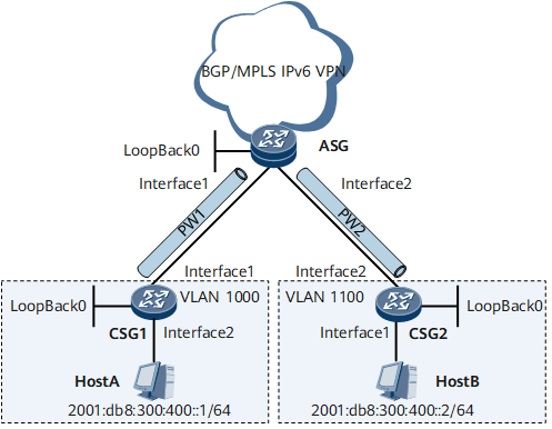
Networking Requirements
If hosts are on the same network segment and physical network but belong to different VLANs, inter-VLAN proxy ND must be enabled on the associated VLAN interfaces to enable Layer 3 interworking between the hosts.

Device Name |
Interface Name |
Interface Address |
|---|---|---|
CSG1 |
GE0/1/1 |
192.168.2.2/24 |
GE0/1/2 |
- |
|
LoopBack0 |
3.3.3.3/32 |
|
CSG2 |
GE0/1/1 |
- |
GE0/1/2 |
192.168.1.2/24 |
|
LoopBack0 |
2.2.2.2/32 |
|
ASG |
GE0/1/1 |
192.168.2.1/24 |
GE0/1/2 |
192.168.1.1/24 |
|
LoopBack0 |
1.1.1.1/32 |
Configuration Roadmap
The configuration roadmap is as follows:
Assign IP addresses to interfaces.
On the ASG, create an L2VE interface for VPWS termination and an L3VE interface for L3VPN access and bind the two VE interfaces to a VE-Group.
- Configure VPWS in LDP mode. Details are as follows:
- Configure a routing protocol to ensure that devices can communicate.
- Configure basic MPLS functions and LDP.
- Enable MPLS L2VPN and create VCs.
Configure dot1q VLAN tag termination sub-interfaces on the ASG and enable inter-VLAN proxy ND.
Data Preparation
To complete the configuration, you need the following data:
Interface addresses
IS-IS process ID
LSR ID
Procedure
- Assign IP addresses to interfaces.
Assign IP addresses to all physical interfaces and loopback interfaces according to Figure 1. For configuration details, see Configuration Files in this section.
- Create VE 0/1/8 and VE 0/1/9 on the ASG and bind the VE interfaces to the same VE-Group.
# Create VE 0/1/8 for MPLS L2VPN termination.
[~ASG] interface virtual-ethernet0/1/8
[*ASG-Virtual-Ethernet0/1/8] ve-group 1 l2-terminate
[*ASG-Virtual-Ethernet0/1/8] quit
# Create VE 0/1/9 for MPLS L3VPN access.
[*ASG] interface virtual-ethernet0/1/9
[*ASG-Virtual-Ethernet0/1/9] ve-group 1 l3-access
[*ASG-Virtual-Ethernet0/1/9] quit
[*ASG] commit
# After completing the configurations, run the display virtual-ethernet ve-group command on the ASG to view the binding relationship between the VE interfaces and VE-Group.
[~ASG] display virtual-ethernet ve-group
 Ve-groupID    TerminateVE                   AccessVE
 1             Virtual-Ethernet0/1/8         Virtual-Ethernet0/1/9
Total 1, 1 printed
- Configure an IGP to allow device communication. IS-IS is used in this example.
During IS-IS configuration, ensure that the routes destined for the 32-bit loopback addresses of the ASG and CSG are advertised.
For configuration details, see Configuration Files in this section.
- Configure basic MPLS functions and LDP.
# Configure CSG1.
[~CSG1] mpls lsr-id 3.3.3.3
[*CSG1] mpls
[*CSG1-mpls] quit
[*CSG1] mpls ldp
[*CSG1-mpls-ldp] quit
[*CSG1] interface gigabitethernet 0/1/1
[*CSG1-GigabitEthernet0/1/1] undo shutdown
[*CSG1-GigabitEthernet0/1/1] mpls
[*CSG1-GigabitEthernet0/1/1] mpls ldp
[*CSG1-GigabitEthernet0/1/1] quit
[*CSG1] commit
# Configure CSG2.
[~CSG2] mpls lsr-id 2.2.2.2
[*CSG2] mpls
[*CSG2-mpls] quit
[*CSG2] mpls ldp
[*CSG2-mpls-ldp] quit
[*CSG2] interface gigabitethernet 0/1/2
[*CSG2-GigabitEthernet0/1/2] undo shutdown
[*CSG2-GigabitEthernet0/1/2] mpls
[*CSG2-GigabitEthernet0/1/2] mpls ldp
[*CSG2-GigabitEthernet0/1/2] quit
[*CSG2] commit
# Configure the ASG.
[~ASG] mpls lsr-id 1.1.1.1
[*ASG] mpls
[*ASG-mpls] quit
[*ASG] mpls ldp
[*ASG-mpls-ldp] quit
[*ASG] interface gigabitethernet 0/1/1
[*ASG-GigabitEthernet0/1/1] undo shutdown
[*ASG-GigabitEthernet0/1/1] mpls
[*ASG-GigabitEthernet0/1/1] mpls ldp
[*ASG-GigabitEthernet0/1/1] quit
[*ASG] interface gigabitethernet 0/1/2
[*ASG-GigabitEthernet0/1/2] undo shutdown
[*ASG-GigabitEthernet0/1/2] mpls
[*ASG-GigabitEthernet0/1/2] mpls ldp
[*ASG-GigabitEthernet0/1/2] quit
[*ASG] commit
- Enable MPLS L2VPN and create VCs.
# Configure CSG1.
[~CSG1] mpls l2vpn
[*CSG1-l2vpn] quit
[*CSG1] interface gigabitethernet 0/1/2.1
[*CSG1-GigabitEthernet0/1/2.1] undo shutdown
[*CSG1-GigabitEthernet0/1/2.1] vlan-type dot1q 1000
[*CSG1-GigabitEthernet0/1/2.1] mpls l2vc 1.1.1.1 1
[*CSG1-GigabitEthernet0/1/2.1] quit
[*CSG1] commit
# Configure CSG2.
[~CSG2] mpls l2vpn
[*CSG2-l2vpn] quit
[*CSG2] interface gigabitethernet 0/1/1.1
[*CSG2-GigabitEthernet0/1/1.1] undo shutdown
[*CSG2-GigabitEthernet0/1/1.1] vlan-type dot1q 1100
[*CSG2-GigabitEthernet0/1/1.1] mpls l2vc 1.1.1.1 1
[*CSG2-GigabitEthernet0/1/1.1] quit
[*CSG2] commit
# Configure the ASG.
[~ASG] mpls l2vpn
[*ASG-l2vpn] quit
[*ASG] interface virtual-ethernet0/1/8.1
[*ASG-Virtual-Ethernet0/1/8.1] vlan-type dot1q 1000
[*ASG-Virtual-Ethernet0/1/8.1] mpls l2vc 3.3.3.3 1
[*ASG-Virtual-Ethernet0/1/8.1] quit
[*ASG] interface virtual-ethernet0/1/8.2
[*ASG-Virtual-Ethernet0/1/8.2] vlan-type dot1q 1100
[*ASG-Virtual-Ethernet0/1/8.2] mpls l2vc 2.2.2.2 1
[*ASG-Virtual-Ethernet0/1/8.2] quit
[*ASG] commit
- Configure dot1q VLAN tag termination sub-interfaces on the ASG and enable inter-VLAN proxy ND.
[~ASG] interface virtual-ethernet0/1/9.1
[*ASG-Virtual-Ethernet0/1/9.1] ipv6 enable
[*ASG-Virtual-Ethernet0/1/9.1] ipv6 address 2001:db8:300:400::3 64
[*ASG-Virtual-Ethernet0/1/9.1] encapsulation dot1q-termination
[*ASG-Virtual-Ethernet0/1/9.1] dot1q termination vid 1000 to 1100
[*ASG-Virtual-Ethernet0/1/9.1] ipv6 nd ns multicast-enable
[*ASG-Virtual-Ethernet0/1/9.1] ipv6 nd proxy inter-access-vlan enable
[*ASG-Virtual-Ethernet0/1/9.1] quit
[*ASG] commit
- Configure the IPv6 addresses of hosts.
# Configure the IPv6 address of Host A as 2001:db8:300:400::1/64.
# Configure the IPv6 address of Host B as 2001:db8:300:400::2/64.
- Verifying the configuration.
After the configurations are complete, Host A and Host B can ping each other.
Configuration Files
CSG1 configuration file
#
sysname CSG1
#
mpls lsr-id 3.3.3.3
#
mpls
#
mpls l2vpn
#
mpls ldp
#
isis 1
 is-level level-1
 network-entity 10.0000.0000.0000.00
 traffic-eng level-2
#
interface GigabitEthernet0/1/1
 undo shutdown
 ip address 192.168.2.2 255.255.255.0
 isis enable 1
 mpls
 mpls ldp
#
interface GigabitEthernet0/1/2
 undo shutdown
#
interface GigabitEthernet0/1/2.1
 vlan-type dot1q 1000
 mpls l2vc 1.1.1.1 1
#
interface LoopBack0
 ip address 3.3.3.3 255.255.255.255
 isis enable 1
#
return
CSG2 configuration file
#
sysname CSG2
#
mpls lsr-id 2.2.2.2
#
mpls
#
mpls l2vpn
#
mpls ldp
#
isis 1
 is-level level-1
 network-entity 10.0000.0000.0001.00
 traffic-eng level-2
#
interface GigabitEthernet0/1/1
 undo shutdown
#
interface GigabitEthernet0/1/1.1
 vlan-type dot1q 1100
 mpls l2vc 1.1.1.1 1
#
interface GigabitEthernet0/1/2
 undo shutdown
 ip address 192.168.1.2 255.255.255.0
 isis enable 1
 mpls
 mpls ldp
#
interface LoopBack0
 ip address 2.2.2.2 255.255.255.255
 isis enable 1
#
return
ASG configuration file
#
sysname ASG
#
mpls lsr-id 1.1.1.1
#
mpls
#
mpls l2vpn
#
mpls ldp
#
isis 1
 is-level level-1
 network-entity 10.0000.0000.0002.00
 traffic-eng level-2
#
interface GigabitEthernet0/1/1
 undo shutdown
 ip address 192.168.2.1 255.255.255.0
 isis enable 1
 mpls
 mpls ldp
#
interface GigabitEthernet0/1/2
 undo shutdown
 ip address 192.168.1.1 255.255.255.0
 isis enable 1
 mpls
 mpls ldp
#
interface LoopBack0
 ip address 1.1.1.1 255.255.255.255
 isis enable 1
#
interface Virtual-Ethernet0/1/8
 ve-group 1 l2-terminate
#
interface Virtual-Ethernet0/1/8.1
 vlan-type dot1q 1000
 mpls l2vc 3.3.3.3 1
#
interface Virtual-Ethernet0/1/8.2
 vlan-type dot1q 1100
 mpls l2vc 2.2.2.2 1
#
interface Virtual-Ethernet0/1/9
 ve-group 1 l3-access
#
interface Virtual-Ethernet0/1/9.1
 ipv6 enable
 ipv6 address 2001:db8:300:400::3/64
 encapsulation dot1q-termination
 dot1q termination vid 1000 to 1100
 ipv6 nd ns multicast-enable
 ipv6 nd proxy inter-access-vlan enable
#
return