NFVI Distributed Gateway (Asymmetric Mode)
Huawei's network functions virtualization infrastructure (NFVI) telco cloud solution incorporates Data Center Interconnect (DCI) and data center network (DCN) solutions. A large volume of UE traffic enters the DCN and accesses the vUGW and vMSE on the DCN. After being processed by the vUGW and vMSE, the UE traffic IPv4 or IPv6 is forwarded over the DCN to destination devices on the Internet. Likewise, return traffic sent from the destination devices to UEs also undergoes this process. To meet the preceding requirements and ensure that the UE traffic is load-balanced within the DCN, you need to deploy the NFVI distributed gateway function on DCN devices.

The vUGW is a unified packet gateway developed based on Huawei's CloudEdge solution. It can be used for 3rd Generation Partnership Project (3GPP) access in general packet radio service (GPRS), Universal Mobile Telecommunications System (UMTS), and Long Term Evolution (LTE) modes. The vUGW can function as a gateway GPRS support node (GGSN), serving gateway (S-GW), or packet data network gateway (P-GW) to meet carriers' various networking requirements in different phases and operational scenarios.
The vMSE is developed based on Huawei's multi-service engine (MSE). The carrier's network has multiple functional boxes deployed, such as the firewall box, video acceleration box, header enrichment box, and URL filtering box. All functions are added through patch installation. As time goes by, the network becomes increasingly slow, complicating service rollout and maintenance. To solve this problem, the vMSE integrates the functions of these boxes and manages these functions in a unified manner, providing value-added services for the data services initiated by users.
Networking Overview
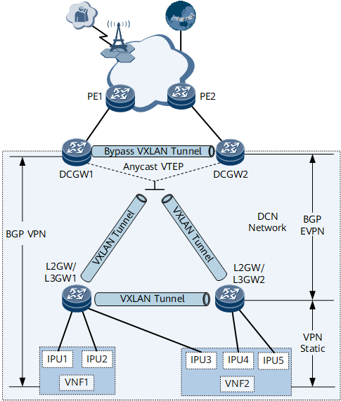
Figure 1 and Figure 2 show NFVI distributed gateway networking. The DC gateways are the DCN's border gateways, which exchange Internet routes with the external network through PEs. L2GW/L3GW1 and L2GW/L3GW2 access the virtualized network functions (VNFs). VNF1 and VNF2 can be deployed as virtualized NEs to implement the vUGW and vMSE functions and connect to L2GW/L3GW1 and L2GW/L3GW2 through the interface processing unit (IPU).
The VXLAN active-active/quad-active gateway function is deployed on DC gateways. Specifically, a bypass VXLAN tunnel is established between DC gateways. All DC gateways use the same virtual anycast VTEP address to establish VXLAN tunnels with L2GW/L3GW1 and L2GW/L3GW2.
The distributed gateway function is deployed on L2GW/L3GW1 and L2GW/L3GW2, and a VXLAN tunnel is established between them.
In the NFVI distributed gateway scenario, the NetEngine 8000 F can function as either a DC gateway or an L2GW/L3GW. However, if the NetEngine 8000 F is used as an L2GW/L3GW, east-west traffic cannot be balanced.
Each L2GW/L3GW in Figure 1 represents two devices on the live network. anycast VXLAN active-active is configured on the devices for them to function as one to improve network reliability.
The method of deploying the VXLAN quad-active gateway function on DC gateways is similar to that of deploying the VXLAN active-active gateway function on DC gateways. This section uses the VXLAN active-active gateway function as an example.
Function Deployment
A VPN BGP peer relationship is set up between each VNF and DC gateway, so that the VNF can advertise UE routes to the DC gateway.
Static VPN routes are configured on L2GW/L3GW1 and L2GW/L3GW2 for them to access VNFs. The routes' destination IP addresses are the VNFs' IP addresses, and the next hop addresses are the IP addresses of the IPUs.
A BGP EVPN peer relationship is established between each DC gateway and L2GW/L3GW. An L2GW/L3GW can flood static routes to the VNFs to other devices through BGP EVPN peer relationships. A DC gateway can advertise local loopback routes and default routes to the L2GWs/L3GWs through the BGP EVPN peer relationships.
Traffic exchanged between a UE and the Internet through a VNF is called north-south traffic, whereas traffic exchanged between VNF1 and VNF2 is called east-west traffic. Load balancing is configured on DC gateways and L2GWs/L3GWs to balance both north-south and east-west traffic.
Generation of Forwarding Entries
BDs are deployed on each L2GW/L3GW and bound to links connecting to the IPU interfaces on the associated network segments. Then, VBDIF interfaces are configured as the gateways of these IPU interfaces. The number of BDs is the same as that of network segments to which the IPU interfaces belong. A static VPN route is configured on each L2GW/L3GW, so that the L2GW/L3GW can generate a route forwarding entry with the destination address being the VNF address, next hop being the IPU address, and outbound interface being the associated VBDIF interface.
Figure 3 Static route forwarding entry on an L2GW/L3GW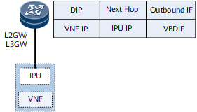
An L2GW/L3GW learns IPU MAC address and ARP information through the data plane, and then advertises the information as an EVPN route to DC gateways. The information is then used to generate an ARP entry and MAC forwarding entry for Layer 2 forwarding.
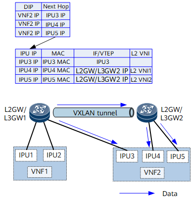
The destination MAC addresses in MAC forwarding entries on the L2GW/L3GW are the MAC addresses of the IPUs. For IPUs directly connecting to an L2GW/L3GW (for example, in Figure 1, IPU1, IPU2, and IPU3 directly connect to L2GW/L3GW1), these IPUs are used as outbound interfaces in the MAC forwarding entries on the L2GW/L3GW. For IPUs connecting to the other L2GW/L3GW (for example, IPU4 and IPU5 connect to L2GW/L3GW2 in Figure 1), the MAC forwarding entries use the VTEP address of the other L2GW/L3GW (L2GW/L3GW2) as the next hop and carry the L2 VNI used for Layer 2 forwarding.
In MAC forwarding entries on a DC gateway, the destination MAC address is the IPU MAC address, and the next hop is the L2GW/L3GW VTEP address. These MAC forwarding entries also store the L2 VNI information of the corresponding BDs.
To forward incoming traffic only at Layer 2, you are advised to configure devices to advertise only ARP (ND) routes to each other. In this way, the DC gateway and L2GW/L3GW do not generate IP prefix routes based on IP addresses. If the devices are configured to advertise IRB (IRBv6) routes to each other, enable the IRB asymmetric mode on devices that receive routes.
Figure 4 MAC forwarding entries on the DC gateway and L2GW/L3GW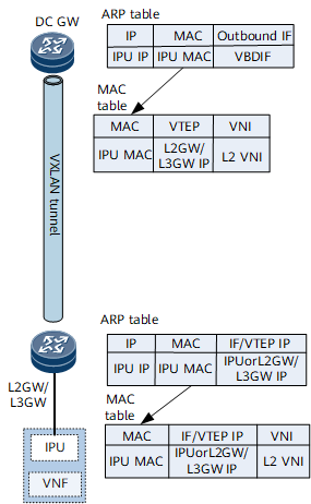
After static VPN routes are configured on the L2GW/L3GW, they are imported into the BGP EVPN routing table and then sent as IP prefix routes to the DC gateway through the BGP EVPN peer relationship.
There are multiple links and static routes between the L2GW/L3GW and VNF. To implement load balancing, you need to enable the Add-Path function when configuring static routes to be imported to the BGP EVPN routing table.
By default, the next hop address of an IP prefix route received by the DC gateway is the IP address of the L2GW/L3GW, and the route recurses to a VXLAN tunnel. In this case, incoming traffic is forwarded at Layer 3. To forward incoming traffic at Layer 2, a routing policy must be configured on the L2GW/L3GW to add the Gateway IP attribute to the static routes destined for the DC gateway. Gateway IP addresses are the IP addresses of IPU interfaces. After receiving an IP prefix route carrying the Gateway IP attribute, the DC gateway does not recurse the route to a VXLAN tunnel. Instead, it performs IP recursion. Finally, the destination address of a route forwarding entry on the DC gateway is the IP address of the VNF, the next hop is the IP address of an IPU interface, and the outbound interface is the VBDIF interface corresponding to the network segment on which the IPU resides. If traffic needs to be sent to the VNF, the forwarding entry can be used to find the corresponding VBDIF interface, which then can be used to find the corresponding ARP entry and MAC entry for Layer 2 forwarding.
Figure 5 Forwarding entries on the DC gateway and L2GW/L3GW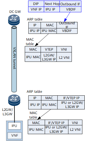
To establish a VPN BGP peer relationship with the VNF, the DC gateway needs to advertise its loopback address to the L2GW/L3GW. In addition, because the DC gateway uses the anycast VTEP address for the L2GW/L3GW, the VNF1-to-DCGW1 loopback protocol packets may be sent to DCGW2. Therefore, the DC gateway needs to advertise its loopback address to the other DC gateway. Finally, each L2GW/L3GW has a forwarding entry for the VPN route to the loopback addresses of DC gateways, and each DC gateway has a forwarding entry for the VPN route to the loopback address of the other DC gateway. After the VNF and DC gateways establish BGP peer relationships, the VNF can send UE routes to the DC gateways, and the next hops of these routes are the VNF IP address.
Figure 6 Forwarding entries on the DC gateway and L2GW/L3GW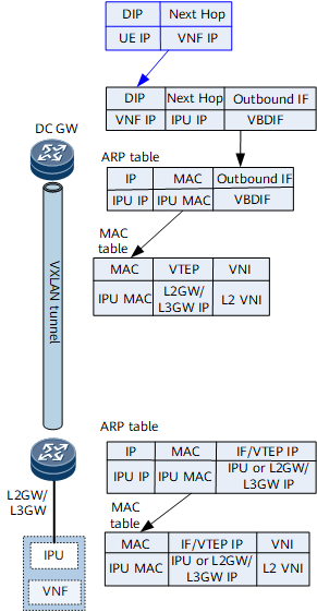
The DCN does not need to be aware of external routes. Therefore, a route policy must be configured on the DC gateway, so that the DC gateway can send default routes and loopback routes to the L2GW/L3GW.
Figure 7 Forwarding entries on the DC gateway and L2GW/L3GW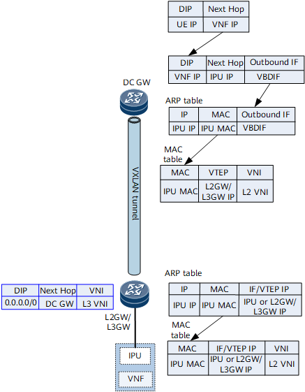
As the border gateway of the DCN, the DC gateway can exchange Internet routes with external PEs, such as routes to server IP addresses on the Internet.
Figure 8 Forwarding entries on the DC gateway and L2GW/L3GW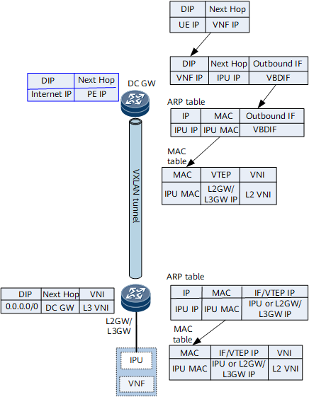
To implement load balancing during traffic transmission, load balancing and Add-Path can be configured on the DC gateway and L2GW/L3GW. This balances both north-south and east-west traffic.
North-south traffic balancing: Take DCGW1 in Figure 1 as an example. DCGW1 can receive EVPN routes to VNF2 from L2GW/L3GW1 and L2GW/L3GW2. By default, after load balancing is configured, DCGW1 sends half of traffic destined for VNF2 to L2GW/L3GW1 and half of traffic destined for VNF2 to L2GW/L3GW2. However, L2GW/L3GW1 has only one link to VNF2, while L2GW/L3GW2 has two links to VNF2. As a result, the traffic is not evenly balanced. To address this issue, the Add-Path function must be configured on the L2GW/L3GWs. After Add-Path is configured, L2GW/L3GW2 advertises two routes with the same destination address to DCGW1 to implement load balancing.
East-west traffic balancing: Take L2GW/L3GW1 in Figure 1 as an example. Because Add-Path is configured on L2GW/L3GW2, L2GW/L3GW1 receives two EVPN routes from L2GW/L3GW2. In addition, L2GW/L3GW1 has a static route with the next hop being IPU3. The destination address of these three routes is the IP address of VNF2. To implement load balancing, load balancing among static and EVPN routes must be configured.
Traffic Forwarding Process
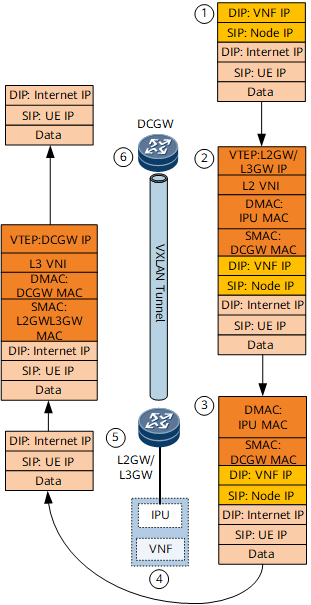
Upon receipt of UE traffic, the base station encapsulates these packets and redirect them to a GPRS tunneling protocol (GTP) tunnel whose destination address is the VNF IP address. The encapsulated packets reach the DC gateway through IP forwarding.
Upon receipt, the DC gateway searches its virtual routing and forwarding (VRF) table and finds a matching forwarding entry whose next hop is an IPU IP address and outbound interface is a VBDIF interface. Therefore, the received packets match the network segment on which the VBDIF interface resides. The DC gateway searches for the desired ARP entry on the network segment, finds a matching MAC forwarding entry based on the ARP entry, and recurses the route to a VXLAN tunnel based on the MAC forwarding entry. Then, the packets are forwarded to the L2GW/L3GW over a VXLAN tunnel.
Upon receipt, the L2GW/L3GW finds the target BD based on the L2 VNI, searches for a matching MAC forwarding entry in the BD, and then forwards the packets to the VNF based on the MAC forwarding entry.
After the packets reach the VNF, the VNF removes their GTP tunnel header, searches the routing table based on their destination IP addresses, and forwards them to the L2GW/L3GW through the VNF's default gateway.
After the packets reach the L2GW/L3GW, the L2GW/L3GW searches their VRF table for a matching forwarding entry. Over the default route advertised by the DC gateway to the L2GW/L3GW, the packets are encapsulated with the L3 VNI and then forwarded to the DC gateway through the VXLAN tunnel.
Upon receipt, the DC gateway searches the corresponding VRF table for a matching forwarding entry based on the L3 VNI and forwards these packets to the Internet.
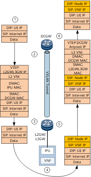
A device on the Internet sends response traffic to a UE. The destination address of the response traffic is the destination address of the UE route. The route is advertised by the VNF to the DC gateway through the VPN BGP peer relationship, and the DC gateway in turn advertises the route to the Internet. Therefore, the response traffic must first be forwarded to the VNF first.
Upon receipt, the DC gateway searches the routing table for a forwarding entry that matches the UE route. The route is advertised over the VPN BGP peer relationship between the DC gateway and VNF and recurses to one or more VBDIF interfaces. Traffic is load-balanced among these VBDIF interfaces. A matching MAC forwarding entry is found based on the ARP information on these VBDIF interfaces. Based on the MAC forwarding entry, the response packets are encapsulated with the L2 VNI and then forwarded to the L2GW/L3GW over a VXLAN tunnel.
Upon receipt, the L2GW/L3GW finds the target BD based on the L2 VNI, searches for a matching MAC forwarding entry in the BD, obtains the outbound interface information from the MAC forwarding entry, and forwards these packets to the VNF.
Upon receipt, the VNF processes them and finds the base station corresponding to the destination address of the UE. The VNF then encapsulates tunnel information into these packets (with the base station as the destination) and forwards these packets to the L2GW/L3GW through the default gateway.
Upon receipt, the L2GW/L3GW searches its VRF table for the default route advertised by the DC gateway to the L2GW/L3GW. Then, the L2GW/L3GW encapsulates these packets with the L3 VNI and forwards them to the DC gateway over a VXLAN tunnel.
Upon receipt, the DC gateway searches its VRF table for the default (or specific) route based on the L3 VNI and forwards these packets to the destination base station. The base station then decapsulates these packets and sends them to the target UE.
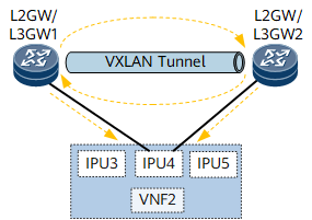
VNF1 sends a received packet to VNF2 for processing. VNF2 re-encapsulates the packet by using its own address as the destination address of the packet and sends the packet to the L2GW/L3GW over the default route.
Upon receipt, the L2GW/L3GW searches its VRF table and finds that multiple load-balancing forwarding entries exist. Some entries use the IPU as the outbound interface, and some entries use the L2GW/L3GW as the next hop.
If the path to the other L2GW/L3GW (L2GW/L3GW2) is selected preferentially, the packet is encapsulated with the L2 VNI and forwarded to L2GW/L3GW2 over a VXLAN tunnel. L2GW/L3GW2 finds the target BD based on the L2 VNI and the destination MAC address, and forwards the packet to VNF2.
Upon receipt, VNF2 processes the packet and forwards it to the Internet server. The subsequent forwarding process is the same as the process for forwarding north-south traffic.