VXLAN Active-Active Reliability
Basic Concepts
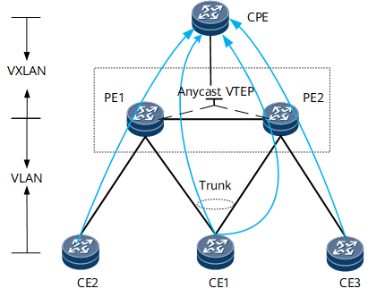
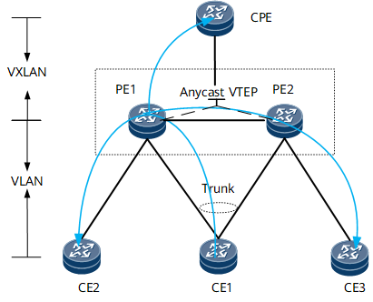
The network in Figure 1 shows a scenario where an enterprise site (CPE) connects to a data center. The VPN GWs (PE1 and PE2) and CPE are connected through VXLAN tunnels to exchange the L2/L3 services between the CPE and data center. The data center gateway (CE1) is dual-homed to PE1 and PE2 to access the VXLAN network for enhanced network access reliability. If one PE fails, services can be rapidly switched to the other PE, minimizing service loss.
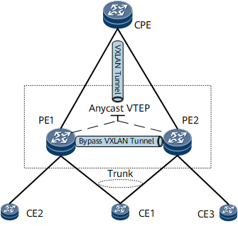
PE1 and PE2 on the network use the same virtual address as an NVE interface address (Anycast VTEP address) at the network side. In this way, the CPE is aware of only one remote NVE interface. After the CPE establishes a VXLAN tunnel with this virtual address, the packets from the CPE can reach CE1 through either PE1 or PE2. However, when a single-homed CE, such as CE2 or CE3, exists on the network, the packets from the CPE to the single-homed CE may need to detour to the other PE after reaching one PE. To achieve PE1-PE2 reachability, a bypass VXLAN tunnel needs to be established between PE1 and PE2. To establish this tunnel, an EVPN peer relationship is established between PE1 and PE2, and different addresses, namely, bypass VTEP addresses, are configured for PE1 and PE2.
Control Plane
PE1 and PE2 exchange Inclusive Multicast routes (Type 3) whose source IP address is their shared anycast VTEP address. Each route carries a bypass VXLAN extended community attribute, which contains the bypass VTEP address of PE1 or PE2.
After receiving the Inclusive Multicast route from each other, PE1 and PE2 consider that they form an anycast relationship based on the following details: The source IP address (anycast VTEP address) of the route is identical to PE1's and PE2's local virtual addresses, and the route carries a bypass VXLAN extended community attribute. PE1 and PE2 then establish a bypass VXLAN tunnel between them.
PE1 and PE2 learn the MAC addresses of the CEs through the upstream packets from the AC side and advertise the MAC/IP routes (Type 2) to each other. The routes carry the ESIs of the access links of the CEs, information about the VLANs that the CEs access, and the bypass VXLAN extended community attribute.
PE1 and PE2 learn the MAC address of the CPE through downstream packets from the network side. After learning that the next-hop address of the MAC route can be recursed to a static VXLAN tunnel, PE1 and PE2 advertise the route to each other through an MAC/IP route, without changing the next-hop address.
Data Packets Processing
Layer 2 unicast packet forwarding
Uplink
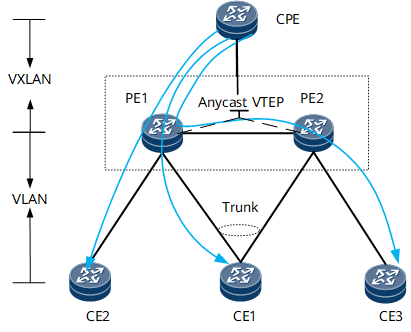
As shown in Figure 2, after receiving Layer 2 unicast packets destined for the CPE from CE1, CE2, and CE3, PE1 and PE2 search for their local MAC address table to obtain outbound interfaces, perform VXLAN encapsulation on the packets, and forward them to the CPE.
Downlink
As shown in Figure 3:
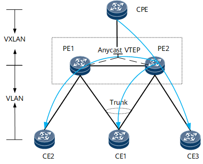
After receiving a Layer 2 unicast packet sent by the CPE to CE1, PE1 performs VXLAN decapsulation on the packet, searches the local MAC address table for the destination MAC address, obtains the outbound interface, and forwards the packet to CE1.
After receiving a Layer 2 unicast packet sent by the CPE to CE2, PE1 performs VXLAN decapsulation on the packet, searches the local MAC address table for the destination MAC address, obtains the outbound interface, and forwards the packet to CE2.
After receiving a Layer 2 unicast packet sent by the CPE to CE3, PE1 performs VXLAN decapsulation on the packet, searches the local MAC address table for the destination MAC address, and forwards it to PE2 over the bypass VXLAN tunnel. After the packet reaches PE2, PE2 searches the destination MAC address, obtains the outbound interface, and forwards the packet to CE3.
The process for PE2 to forward packets from the CPE is the same as that for PE1 to forward packets from the CPE.
BUM packet forwarding
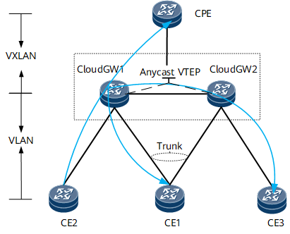
As shown in Figure 4, if the destination address of a BUM packet from the CPE is the Anycast VTEP address of PE1 and PE2, the BUM packet may be forwarded to either PE1 or PE2. If the BUM packet reaches PE2 first, PE2 sends a copy of the packet to CE3 and CE1. In addition, PE2 sends a copy of the packet to PE1 through the bypass VXLAN tunnel between PE1 and PE2. After the copy of the packet reaches PE1, PE1 sends it to CE2, not to the CPE or CE1. In this way, CE1 receives only one copy of the packet.
As shown in Figure 5, after a BUM packet from CE2 reaches PE1, PE1 sends a copy of the packet to CE1 and the CPE. In addition, PE1 sends a copy of the packet to PE2 through the bypass VXLAN tunnel between PE1 and PE2. After the copy of the packet reaches PE2, PE2 sends it to CE3, not to the CPE or CE1.
As shown in Figure 6, after a BUM packet from CE1 reaches PE1, PE1 sends a copy of the packet to CE2 and the CPE. In addition, PE1 sends a copy of the packet to PE2 through the bypass VXLAN tunnel between PE1 and PE2. After the copy of the packet reaches PE2, PE2 sends it to CE3, not to the CPE or CE1.
Layer 3 packets transmitted on the same subnet
Uplink
As shown in Figure 2, after receiving Layer 3 unicast packets destined for the CPE from CE1, CE2, and CE3, PE1 and PE2 search for the destination address and directly forward them to the CPE because they are on the same network segment.
Downlink
As shown in Figure 3:
After the Layer 3 unicast packet sent from the CPE to CE1 reaches PE1, PE1 searches for the destination address and directly sends it to CE1 because they are on the same network segment.
After the Layer 3 unicast packet sent from the CPE to CE2 reaches PE1, PE1 searches for the destination address and directly sends it to CE2 because they are on the same network segment.
After the Layer 3 unicast packet sent from the CPE to CE3 reaches PE1, PE1 searches for the destination address and sends it to PE2, then sends it to CE3, because they are on the same network segment.
The process for PE2 to forward packets from the CPE is the same as that for PE1 to forward packets from the CPE.
Layer 3 packets transmitted across subnets
Uplink
As shown in Figure 2:
Because the CPE is on a different network segment from PE1 and PE2, the destination MAC address of a Layer 3 unicast packet sent from CE1, CE2, or CE3 to the CPE is the MAC address of the BDIF interface on the Layer 3 gateway of PE1 or PE2. After receiving the packet, PE1 or PE2 removes the Layer 2 tag from the packet, searches for a matching Layer 3 routing entry, and obtains the outbound interface that is the BDIF interface connecting the CPE to the Layer 3 gateway. The BDIF interface searches the ARP table, obtains the destination MAC address, encapsulates the packet into a VXLAN packet, and sends it to the CPE through the VXLAN tunnel.
After receiving the Layer 3 packet from PE1 or PE2, the CPE removes the Layer 2 tag from the packet because the destination MAC address is the MAC address of the BDIF interface on the CPE. Then the CPE searches the Layer 3 routing table to obtain a next-hop address to forward the packet.
Downlink
As shown in Figure 3:
Before sending a Layer 3 unicast packet to CE1 across subnets, the CPE searches its Layer 3 routing table and obtains the outbound interface that is the BDIF interface on the Layer 3 gateway connecting to PE1. The BDIF interface searches the ARP table to obtain the destination MAC address, encapsulates the packet into a VXLAN packet, and forwards it to PE1 over the VXLAN tunnel.
After receiving the packet from the CPE, PE1 removes the Layer 2 tag from the packet because the destination address of the packet is the MAC address of PE1's BDIF interface. Then PE1 searches the Layer 3 routing table and obtains the outbound interface that is the BDIF interface connecting PE1 to its attached CE. The BDIF interface searches its ARP table and obtains the destination address, performs Layer-2 encapsulation for the packet, and sends it to CE1.
The process for PE2 to forward packets from the CPE is the same as that for PE1 to forward packets from the CPE.