NFVI Distributed Gateway (SR Tunnels)
The network function virtualization infrastructure (NFVI) telco cloud solution uses the data center interconnect (DCI)+data center network (DCN) networking. A large amount of mobile phone traffic is sent to virtual unified gateways (vUGWs) and virtual multiservice engines (vMSEs) on the DCN. After being processed by the vUGWs and vMSEs, the IPv4 or IPv6 mobile phone traffic is forwarded over the DCN to destination devices on the Internet. The destination devices send traffic to mobile phones in similar ways. To achieve these functions and ensure traffic load balancing on the DCN, you need to deploy the NFVI distributed gateway function.

A vUGW is a unified gateway developed for Huawei's CloudEdge solution, which can be used for 3GPP access in GPRS, UMTS, and LTE modes. A vUGW can be a GGSN, an S-GW, or a P-GW, which meets the networking requirements of carriers in different stages and operations scenarios.
A vMSE is a virtual type of an MSE. The current carrier network includes multiple functional boxes, including the firewall box, video acceleration box, header enhancement box, and URL filter box. All of these functions are enabled through patch installation, causing a more and more complex network and difficult service provisioning and maintenance. To address the problems, vMSEs incorporate the functions of these boxes, uniformly manage these functions, and implement value-added service processing for the data service initiated by users.
The NFVI distributed gateway function supports service traffic transmission over SR or VXLAN tunnels. SR tunnels are classified as SR tunnels or E2E SR tunnels. This section describes the implementation of the NFVI distributed gateway function for traffic transmission over SR tunnels.
Networking Introduction
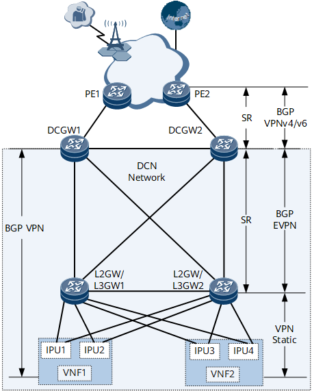
Figure 1 shows the networking of an NFVI distributed gateway (SR tunnels). DC-GWs, which are the border gateways of the DCN, exchange Internet routes with external devices over PEs. L2GW/L3GW1 and L2GW/L3GW2 are connected to VNFs. VNF1 and VNF2 that function as virtualized NEs are deployed to implement the vUGW functions and vMSE functions, respectively. VNF1 and VNF2 are each connected to L2GW/L3GW1 and L2GW/L3GW2 through IPUs.
Function Deployment
Establish BGP VPN peer relationships between VNFs and DC-GWs so that the VNFs can advertise mobile phone routes (UE IP) to DC-GWs.
On L2GW/L3GW1 and L2GW/L3GW2, configure static VPN routes with the IP addresses of VNFs as the destination addresses and the IP addresses of IPUs as next-hop addresses.
Establish BGP EVPN peer relationships between any DC-GW and L2GW/L3GW. An L2GW/L3GW can flood static routes destined for VNFs to other devices through BGP EVPN peer relationships. A DC gateway can advertise local loopback routes and default routes to L2GWs/L3GWs through BGP EVPN peer relationships.
Establish BGP VPNv4/v6 peer relationships between DC-GWs and PEs. DC-GWs can then advertise mobile phone routes to PEs and receive the Internet routes sent by external devices based on the BGP VPNv4/v6 peer relationships.
Deploy SR tunnels between PEs and DC-GWs and between DC-GWs and L2GW/L3GWs to carry service traffic.
The traffic transmitted between mobile phones and the Internet over VNFs is north-south traffic. The traffic transmitted between VNF1 and VNF2 is east-west traffic. To achieve load balancing of east-west traffic and north-south traffic, deploy the load balancing function on DC-GWs and L2GW/L3GWs.
Establishment of Forwarding Entries
On L2GW/L3GWs, the number of BDs is planned based on the number of network segments corresponding to the IPUs, the BDs are bound to the links connecting to the corresponding IPUs, and VBDIF interfaces are configured as the gateways of IPUs. Static VPN routes are configured on L2GW/L3GWs so that the forwarding entries with the destination address as a VNF's address, the next-hop address as an IPU's IP address, and outbound interface as the VBDIF interface can be established on L2GW/L3GWs.
Figure 2 Forwarding entries of static routes on L2GW/L3GWs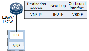
L2GW/L3GWs learn the MAC addresses and ARP information of IPUs through the data plane. Such information is advertised to DC-GWs through EVPN routes and can be used for establishment of ARP entries and MAC entries for Layer 2 forwarding.
The destination MAC addresses in the MAC entries on L2GW/L3GWs are IPUs' MAC addresses. For the IPU directly connected to an L2GW/L3GW, this IPU is used as the outbound interface in MAC entries. For the IPUs (such as IPU3 and IPU4 corresponding to L2GW/L3GW2 in Figure 1) connecting to non-direct-link L2GW/L3GWs, MAC entries include the outbound interfaces of SR tunnels and the next-hop addresses, namely, the IP addresses of the BGP EVPN peers of these L2GW/L3GWs.
In the MAC entries on DC-GWs, the destination MAC address is an IPU's MAC address, the IP address of the BGP EVPN peer of an L2GW/L3GW is the next-hop address, and the outbound interface is the one for traffic forwarding over SR tunnels.
To allow inbound traffic to be forwarded only at Layer 2, configure these devices to advertise only ARP or ND routes. In this manner, DC-GWs and L2GW/L3GWs do not generate IP prefix routes based on IP addresses. If these devices are configured to advertise IRB or IRBv6 routes, you need to enable asymmetric IRB on the devices receiving routes.
Figure 3 MAC entries on DC-GWs and L2GW/L3GWs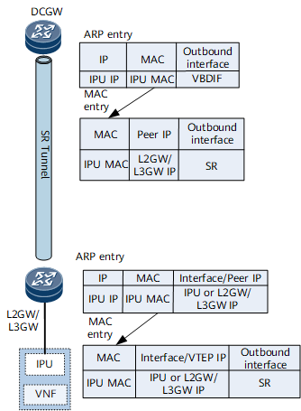
After static VPN routes are configured on L2GW/L3GWs, these static VPN routes are imported to the BGP EVPN routing table and sent to DC-GWs as IP prefix routes based on BGP EVPN peer relationships.
Because multiple links and static routes exist between L2GW/L3GWs and VNFs, to achieve load balancing, the Add-Path function needs to be enabled during configuration of importing static routes to the BGP EVPN routing table.
By default, the next-hop address of the IP prefix routes received by DC-GWs is the IP address of an L2GW/L3GW and routes are recursed over SR tunnels. This allows inbound traffic to be forwarded at Layer 3. To achieve Layer 2 forwarding of inbound traffic, a route-policy needs to be deployed on L2GW/L3GWs to add the Gateway IP attribute to the static routes destined for DC-GWs. The gateway IP attribute indicates the IP address of an IPU. Upon receipt of the IP prefix routes carrying the gateway IP attribute, DC-GWs recurse routes to next-hop IP addresses, instead of tunnels. In this manner, the destination IP address of the forwarding entries on DC-GWs is a VNF's IP address, the next-hop address is an IPU's IP address, and the outbound interface is the VBDIF interface corresponding to the network segment where the IPU resides. The VBDIF interface looks for a forwarding entry mapped to each VNF IP address and locates the outbound VBDIF interface. ARP entries and MAC entries can be located based on the VBDIF interface to implement Layer 2 forwarding.
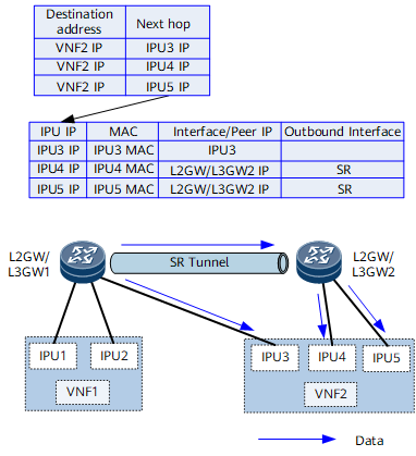
Figure 4 Forwarding entries on DC-GWs and L2GW/L3GWs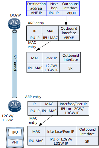
To establish BGP VPN peer relationships between DC-GWs and VNFs, DC-GWs need to advertise the routes destined for loopback addresses to L2GW/L3GWs. After BGP VPN peer relationships are established between DC-GWs and VNFs, VNFs can send DC-GWs the mobile phone routes whose next-hop address is a VNF's IP address.
Figure 5 Forwarding entries on DC-GWs and L2GW/L3GWs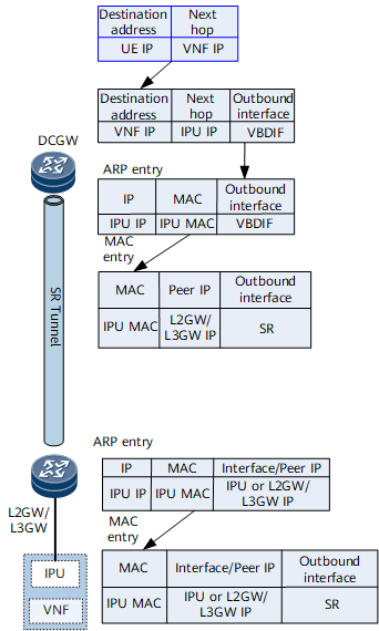
Devices on the DCN do not need to get aware of external routes. Therefore, a route-policy needs to be configured on DC-GWs to allow DC-GWs to send only default routes except for the loopback routes to L2GW/L3GWs.
Figure 6 Forwarding entries on DC-GWs and L2GW/L3GWs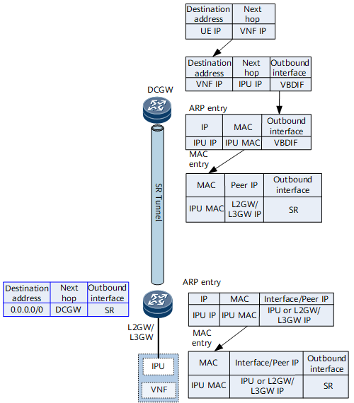
DC-GWs function as the border gateways of the DCN and can exchange Internet route information, such as the Internet server address, with PEs.
Figure 7 Forwarding entries on DC-GWs and L2GW/L3GWs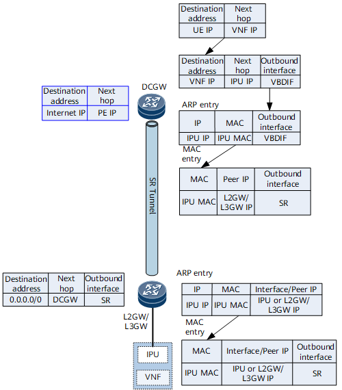
PEs can obtain mobile phone routes and the routes carrying VNFs' IP addresses from DC-GWs based on BGP VPNv4/v6 peer relationships. The next-hop addresses of these routes are DC-GWs' IP addresses, and the outbound interface is an SR tunnel connecting to a DC-GW.
Figure 8 Forwarding entries on PEs, DC-GWs and L2GW/L3GWs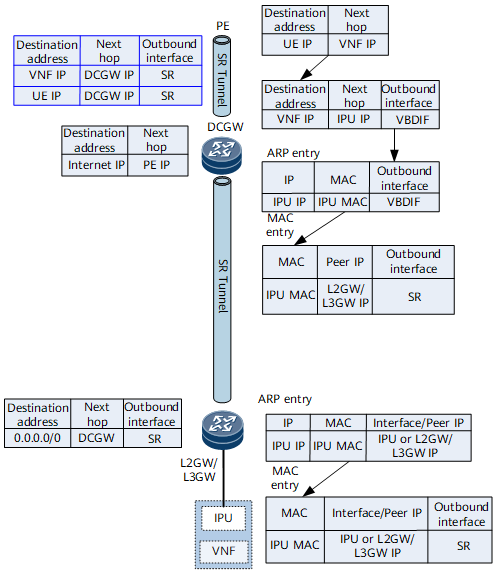
To achieve load balancing of east-west traffic and north-south traffic, the load balancing function and Add-Path function need to be deployed on DC-GWs and L2GW/L3GWs.
Load balancing of north-south traffic: Taking DC-GW1 in Figure 1 as an example, DC-GW1 can receive the EVPN routes destined for VNF2 from L2GW/L3GW1 and L2GW/L3GW2. By default, after the load balancing function is configured, DC-GW1 sends half of the traffic destined for VNF2 through L2GW/L3GW1 and the other half of the traffic through L2GW/L3GW2. However, L2GW/L3GW1 connects to VNF2 over one link and L2GW/L3GW2 connects to VNF2 over two links, causing the load balancing function failed to achieve the desired effect. Therefore, the Add-Path function needs to be deployed on L2GW/L3GWs. After the Add-Path function is deployed on L2GW/L3GWs, L2GW/L3GW2 sends two routes with the same destination address to DC-GW1, achieving load balancing.
East-west traffic load balancing: Taking L2GW/L3GW1 in Figure 1 as an example, because the Add-Path function is deployed on L2GW/L3GW2, L2GW/L3GW1 receives two EVPN routes from L2GW/L3GW2 and L2GW/L3GW1 has a static route with the next-hop address as IPU3's IP address. The destination addresses of all these routes are VNF2's IP address. Therefore, the load balancing function needs to be configured to balance traffic over static routes and EVPN routes.
Traffic Forwarding Process
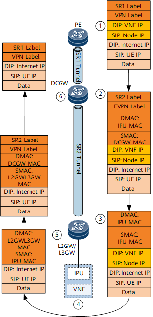
Mobile phone traffic is sent to base stations (Nodes) and encapsulated with a GPRS tunneling protocol (GTP) header. The destination IP address of the GTP tunnel is a VNF's IP address. PEs send the encapsulated packets to DC-GWs over SR tunnels based on the VPN routing table.
Upon receipt of the encapsulated packets, DC-GWs look for the VPN routing table and find that the next-hop addresses of the forwarding entries corresponding to VNFs' IP addresses are IPUs' IP addresses and the outbound interface is the VBDIF interface. Therefore, routes destined for the network segment corresponding to the VBDIF interface are hit. DC-GWs search the MAC address that belongs to the network segment in an ARP table, look for the MAC forwarding table based on the ARP information, and forward traffic to L2GW/L3GWs over SR tunnels based on the MAC forwarding table.
Upon receipt of packets, L2GW/L3GWs find the corresponding BDs based on EVPN labels, look for MAC forwarding entries in the BDs, and forward traffic to VNFs based on the MAC information.
Upon receipt of packets, VNFs decapsulate the GTP tunnel header, search the routing table based on the destination IP address in the decapsulated packets, and forward the packets to L2GW/L3GWs based on the default gateways of VNFs.
L2GW/L3GWs search for the VPN routing table on L2GW/L3GWs. The default routes advertised by DC-GWs to L2GW/L3GWs are recursed over SR tunnels and forwarded to DC-GWs after being encapsulated with a VPN label.
DC-GWs forward the packets to PEs using the VPN forwarding table found based on VPN labels. Specifically, the packets are re-encapsulated with a VPN label and an SR label before they are forwarded to PEs.
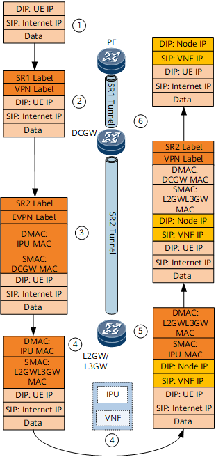
Devices on the Internet send mobile phones the reply packets whose destination IP addresses are the IP addresses of mobile phones. This is because mobile phone routes are advertised by VNFs to DC-GWs based on BGP VPN peer relationships and then advertised to the Internet by DC-GWs through PEs. Therefore, reply packets must be first transmitted to VNFs.
Upon receipt of reply packets, PEs search the VPN routing table for the forwarding entries corresponding to mobile phone routes whose next-hop addresses are DC-GWs' IP addresses and the outbound interface is the one for SR tunnels. The reply packets are sent to DC-GWs after being encapsulated with a VPN label and an SR label.
Upon receipt of the reply packets, DC-GWs search the VPN routing table for the forwarding entries corresponding to the mobile phone routes based on the BGP VPN peer relationships between DC-GWs and VNFs. These routes are recursed to one or more VBDIF interfaces, and traffic is load balanced to these VBDIF interfaces. The VBDIF interfaces look for ARP information and MAC forwarding entries. Based on the MAC entries, the reply packets are forwarded to L2GW/L3GWs over SR tunnels after being encapsulated with an EVPN label.
Upon receipt of the reply packets, L2GW/L3GWs find the corresponding BDs based on the EVPN label and search for the MAC forwarding entries. The outbound interface information is then obtained based on the MAC forwarding entries. The reply packets are then forwarded to VNFs.
Upon receipt of the reply packets, VNFs search for the base stations corresponding to the destination IP addresses of mobile phones and add a tag of tunnel information with the destination IP address as the IP address of a base station. The reply packets are then forwarded to L2GW/L3GWs based on default gateways.
Upon receipt of the reply packets, L2GW/L3GWs search the VPN routing table, and the default routes advertised by DC-GWs to L2GW/L3GWs are hit. The reply packets are then forwarded to DC-GWs over SR tunnels after being encapsulated with a VPN label.
Upon receipt of the reply packets, DC-GWs find the corresponding VPN forwarding table based on the VPN label, and the default routes or specific routes are hit. The reply packets are then forwarded to PEs over SR tunnels and then from PEs to base stations. After being encapsulated by base stations, the reply packets are sent to the corresponding mobile phones.
Upon receipt of user packets, VNF1 finds that the packets need to be processed by VNF2 and then adds a tunnel label with the destination IP address as VNF2's IP address. The user packets are sent to L2GW/L3GWs based on default routes.
Upon receipt of user packets, an L2GW/L3GW searches the VPN forwarding table and finds that multiple load-balancing forwarding entries exist. In some entries, the outbound interface is an IPU or the next-hop address is the IP address of another L2GW/L3GW.
If the traffic hits the path of another L2GW/L3GW, an EVPN label is added to the user packets and the routes are recursed to L2GW/L3GW2 over an SR tunnel. L2GW/L3GW2 searches for the BD and destination MAC address based on the EVPN label before forwarding the packets to VNF2.
Upon receipt of the user packets, VNF2 processes and forwards the packets to the server. The subsequent forwarding follows the north-south traffic forwarding procedure.