Multi-Segment PW Redundancy
Multi-segment PW (MS-PW) redundancy applies to the following scenarios:
- A PE is single-homed to an SPE.
- A PE is dual-homed to two SPEs.
MS-PW Redundancy When a PE Is Single-Homed to an SPE
On the network shown in Figure 1, when primary and secondary PWs cannot be configured on PE1, you can configure primary and secondary PWs on the SPE to implement protection. The L2VPN service between PE1 and the SPE is in PWE3 mode. A common PW is configured on PE1. The primary and secondary PWs with label switching are configured on the SPE. A bypass PW is configured between PE2 and PE3.
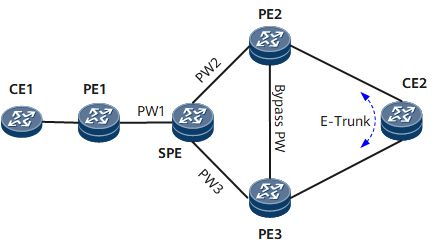
Normal Scenario
- Uplink: After the packets sent by CE1 reach PE1, they pass through PW1 to the SPE and then through PW2 to PE2. Finally, the packets are forwarded to CE2 through the AC interface on PE2.
- Downlink: After the packets sent by CE2 reach PE2, PE2 forwards the packets to the SPE through PW2. Then, the SPE forwards the packets to PE1 through PW1. Finally, PE1 forwards the packets to CE1.
Fault Scenario
If the link between the SPE and PE2 fails, packets are transmitted along the following paths:
- Uplink: CE1 -> PE1 -> SPE -> PE3 -> PE2-> CE2
- Downlink: CE2 -> PE2 -> PE3 -> SPE -> PE1 -> CE1
If PE2 fails, packets are transmitted along the following paths:
- Uplink: CE1 -> PE1 -> SPE -> PE3 -> CE2
- Downlink: CE2 -> PE3 -> SPE -> PE1 -> CE1
If the link between PE2 and CE2 fails, packets are transmitted along the following paths:
- Uplink: CE1 -> PE1 -> SPE -> PE2 -> PE3 -> CE2
- Downlink: CE2 -> PE3 -> PE2 -> SPE -> PE1 -> CE1
MS-PW Redundancy When a PE Is Dual-Homed to SPEs
On the network shown in Figure 2, PE1 is dual-homed to SPE1 and SPE2, which are in turn dual-homed to PE2 and PE3. A Spoken PW is deployed between PE2 and PE3. Dynamic SS-PWs are configured on PE1, and PW redundancy is in master/slave mode. Dual receive mode is not configured for the PWs. Dynamic MS-PWs are configured on SPE1 and SPE2. SPE1 switches PW1 to PW3 and PW4, whereas SPE2 switches PW2 to PW5 and PW6. The PW redundancy protection group is in master/slave mode. Dual receive mode is not configured for the PWs.
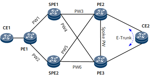
Normal Scenario
- Uplink: After the packets sent by CE1 reach PE1, PE1 forwards the packets to SPE1 through PW1. Then, SPE1 forwards the packets to PE2 through PW3. Finally, the packets are forwarded to CE2 through the AC interface on PE2.
- Downlink: After the packets sent by CE2 reach PE2, PE2 forwards the packets to SPE1 through PW3. Then, SPE1 forwards the packets to PE1 through PW1. Finally, PE1 forwards the packets to CE1.
Fault Scenario
If the link between PE1 and SPE1 fails, packets are transmitted along the following paths:
- Uplink: CE1 -> PE1 -> SPE2 -> PE2 -> CE2
- Downlink: CE2 -> PE2 -> SPE2 -> PE1 -> CE1
If SPE1 fails, packets are transmitted along the following paths:
- Uplink: CE1 -> PE1 -> SPE2 -> PE2 -> CE2
- Downlink: CE2 -> PE2 -> SPE2 -> PE1 -> CE1
If the link between SPE1 and PE2 fails, packets are transmitted along the following paths:
- Uplink: CE1 -> PE1 -> SPE1 -> PE3 -> PE2 -> CE2
- Downlink: CE2 -> PE2 -> PE3 -> SPE1 -> PE1 -> CE1
If PE2 fails, packets are transmitted along the following paths:
- Uplink: CE1 -> PE1 -> SPE1 -> PE3 -> CE2
- Downlink: CE2 -> PE3 -> SPE1 -> PE1 -> CE1
If the link between CE2 and PE2 fails, packets are transmitted along the following paths:
- Uplink: CE1 -> PE1 -> SPE1 -> PE2 -> PE3 -> CE2
- Downlink: CE2 -> PE3 -> PE2 -> SPE1 -> PE1 -> CE1