Mutual Protection Between an LDP VC and a CCC VC

The use of Layer 2 virtual private network (L2VPN) technologies increases reliability requirements for L2VPNs. This is especially true of L2VPNs that provide real-time services such as VoIP and Internet Protocol television (IPTV).

Configuring mutual protection between a Label Distribution Protocol (LDP) virtual channel (VC) and a circuit cross connect (CCC) VC can meet these requirements. A CCC VC and an LDP VC work in the active/standby mode to protect traffic over each other. If an active path goes Down, traffic is switched to the standby path, therefore improving CCC VC's and LDP VC's reliability.

Single-Homing 2PE Scenario

Figure 1 shows the following:
  • CE1 is single-homed to PE1 through AC1 and preferentially accesses CE2 through AC2.
  • A PW is established between PE1 and PE2, with PW AC1 protecting traffic transmitted through AC2.

If AC2 fails, CE1 accesses CE3 through the path CE1->AC1->PW VC1->AC3->CE3.

Because PE1 and PE2 are connected to different CEs, they cannot detect the active/standby status of the CEs. In this case, they have to use the active/standby mode to determine the CEs' status. The configuration roadmap is as follows:
  • For AC1->AC2 traffic, the PW functions as the standby path of AC2.
  • The path AC2->AC1 does not have a standby path.
  • The path AC3->PW VC1 does not have a standby path.
Figure 1 Mutual protection between a CCC VC and an LDP VC (single-homing 2PE scenario)

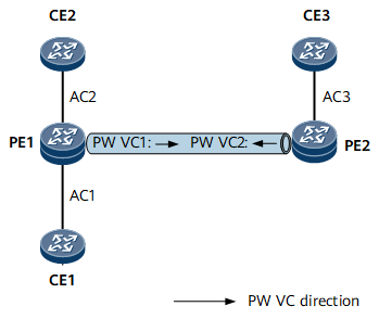
CE2 and CE3 are the active and standby devices respectively in the preceding illustration. In that case, an LDP VC (PW VC1) protects traffic transmitted through a CCC VC (AC2). In real-time deployment, CE3 and CE2 may be the active and standby devices, respectively. In this case, a CCC VC (AC2) protects traffic transmitted through an LDP VC (PW VC1). The configuration roadmap is the same in both cases, so the roadmap for configuring a CCC VC to protect an LDP VC is not described here.

Table 1 Scenarios where typical faults trigger switchovers

Fault Point

Switchover

AC2 or CE2 failure when:
  • CE2 is in the active state.
  • CE3 is in the standby state.

In this case, an LDP VC protects a CCC VC.

  1. When detecting AC2 or CE2 failure, PE1 switches traffic to the PW. Then traffic between CE1 and CE3 is transmitted through the path CE1<->AC1<->PW<->AC3<->CE3.
  2. After AC2 or CE2 recovers, PE1 switches traffic back to AC2 based on a configured revertive switching policy.
PE2, AC3, CE3, or PW failure when:
  • CE3 is in the active state.
  • CE2 is in the standby state.

In this case, a CCC VC protects an LDP VC.

  1. When detecting the failure, PE1 switches traffic to AC2. Then traffic between CE1 and CE2 is transmitted through the path CE1<->AC1<->AC2<->CE2.
  2. After PE2, AC3, CE3, or the PW recovers, PE1 switches traffic back to the PW based on the configured revertive switching policy.

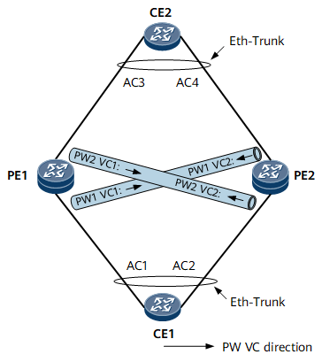
Dual-Homing 2PE Scenario

Figure 2 shows the following:
  • CE1 is dual-homed to PE1 and PE2 through an Eth-Trunk, with AC1 serving as the active path.
  • CE2 is dual-homed to PE1 and PE2 through another Eth-Trunk, with AC3 serving as the active path.
  • PW1 VC1 is deployed between PE1 and PE2 to protect AC3. If AC3 fails, CE1 accesses CE2 through the PW1 VC1->AC4 path.
  • PW2 VC1 is deployed between PE1 and PE2 to protect AC1. If AC1 fails, CE2 accesses CE1 through the PW2 VC1->AC2 path.

Based on the preceding, CE1 and CE2 select AC1 and AC3 as the active paths, respectively. They select AC2 and AC4 as the standby paths, respectively. If the active paths fail, the standby paths take over service traffic.

Because CE1 and CE2 both use Eth-Trunks to access the PEs, the active/standby Eth-Trunk status determines the active/standby status of the PWs connected to PE1 and PE2. The roadmap for configuring an LDP VC to protect a CCC VC is as follows:
  • For AC1->AC3 traffic, configure PW1 VC1 on the AC1 interface to protect AC3.
  • For AC2->PW2 VC2 traffic, configure PW2 VC2 on the AC2 interface to protect AC4.
  • For AC3->AC1 traffic, configure PW2 VC1 on the AC3 interface to protect AC1.
  • For AC4->PW1 VC2 traffic, configure PW1 VC2 on the AC4 interface to protect AC2.
Figure 2 LDP VC protecting CCC VC (dual-homing 2PE scenario)

Table 2 Scenarios where typical faults trigger switchovers

Fault Point

Switchover

AC1 fails.

  1. After detecting AC1 failure, the Eth-Trunk on CE1 switches traffic from AC1 to AC2. Because AC4 is blocked, PW2 VC2 functions as the active path, and the traffic between CE1 and CE2 is transmitted through the path CE1<->AC2<->PW2<->AC3<->CE2.
  2. After AC1 recovers, the Eth-Trunk on CE1 switches traffic back to AC1. Then traffic between CE1 and CE2 is transmitted through the path CE1<->AC1<->AC3<->CE2.

AC3 fails.

  1. After detecting AC3 failure, the Eth-Trunk on CE2 switches traffic from AC3 to AC4. Because AC2 is blocked, PW1 VC2 functions as the active path, and the traffic between CE2 and CE1 is transmitted through the path CE2<->AC4<->PW1<->AC1<->CE1.
  2. After AC3 recovers, the Eth-Trunk on CE2 switches traffic back to AC3. Then traffic between CE2 and CE1 is transmitted through the path CE2<->AC3<->AC1<->CE1.

PE1 fails.

  1. After detecting PE1 failure, the Eth-Trunks on CE1 and CE2 switch traffic from AC1 to AC2 and from AC3 to AC4, respectively. Then traffic between CE1 and CE2 is transmitted through the path CE1<->AC2<->AC4<->CE2.
  2. After PE1 recovers, the Eth-Trunks on CE1 and CE2 switch traffic back to AC1 and AC3. Then traffic between CE1 and CE2 is transmitted through the path CE1<->AC1<->AC3<->CE2.

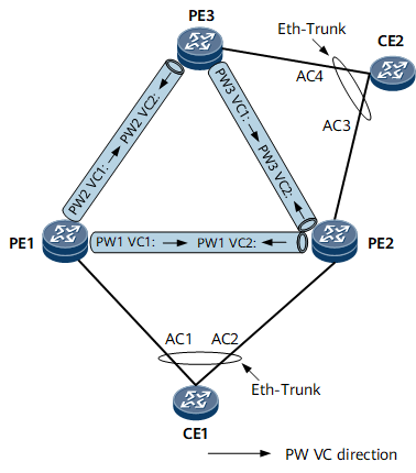
Dual-Homing 3PE Scenario

Figure 3 shows the following:
  • CE1 is dual-homed to PE1 and PE2 through an Eth-Trunk. AC1 serves as the active path, and AC2 serves as the standby path.
  • CE2 is dual-homed to PE2 and PE3 through another Eth-Trunk. AC3 serves as the active path, and AC4 serves as the standby path.
  • PW redundancy in Independent mode is configured on PE1, with PW1 VC1 being the active PW and PW2 VC1 being the standby PW.
  • PW redundancy in Independent mode is configured on PE3, with PW2 VC2 being the active PW and PW3 VC1 being the standby PW.

The PW1 VC1 (active) and PW2 VC1 (standby) paths can be used to transmit traffic from AC1 to CE2. The AC3 (active) and PW3 VC2 (standby) paths can be used to transmit traffic from AC2 to CE2.

Figure 3 LDP VC protecting CCC VC (dual-homing 3PE scenario)
An Eth-Trunk priority determines the active/standby status of the ACs on PE1, PE2, and PE3. There are four combinations of AC status in this scenario. The following example uses two combinations of AC status:
  • AC1 and AC3 serve as the active paths, and AC2 and AC4 serve as the standby paths:
    • For AC1->PW1 VC1 traffic, configure PW redundancy on the AC1 interface, with PW1 VC1 being the active path and PW2 VC1 being the standby path.
    • For AC2->AC3 traffic, configure PW3 VC2 on the AC2 interface to protect AC3.
    • For AC3->PW1 VC2 traffic, configure PW1 VC2 on the AC3 interface to protect AC2.
    • For AC4->PW2 VC2 traffic, configure PW redundancy on the AC4 interface, with PW2 VC2 being the active path and PW3 VC1 being the standby path.
  • AC2 and AC3 serve as the active paths, and AC1 and AC4 serve as the standby paths:
    • For AC1->PW1 VC1 traffic, configure PW redundancy on the AC1 interface, with PW1 VC1 being the active path and PW2 VC1 being the standby path.
    • For AC2->AC3 traffic, configure PW3 VC2 on the AC2 interface to protect AC3.
    • For AC3->AC2 traffic, configure PW1 VC2 on the AC3 interface to protect AC2.
    • For AC4->PW3 VC1 traffic, configure PW redundancy on the AC4 interface, with PW2 VC2 being the active path and PW3 VC1 being the standby path.
Table 3 Scenarios where typical faults trigger switchovers

Fault Point

Switchover

AC3 failure when:
  • AC1 and AC3 serve as the active paths.
  • AC2 and AC4 serve as the standby paths.
  1. After detecting AC3 failure, the Eth-Trunk on PE3 switches traffic from AC3 to AC4, and AC4 serves as the active path.
  2. PE3 instructs PW2 VC2 to switch to the active state, and PE2 instructs PW1 VC2 to switch to the standby state. Then traffic between CE1 and CE2 is transmitted through the path CE1<->AC1<->PW2<->AC4<->CE2.
    NOTE:

    It takes some time for PE3 to detect the status change of AC4 and to notify PE1 that PW2 VC2 has switched to the active state. The amount of time that elapses depends on the signaling convergence speed. At this time, PW2 VC2 remains in the standby state, and traffic may be discarded if transmitted through the path CE2->AC4->PW2 VC2->AC1->CE1. To resolve this problem, enable PE1 to accept traffic sent from a standby PW.

  3. After AC3 recovers, PE2 switches to the active state, and PE3 switches to the standby state. After signaling convergence is complete, traffic between CE1 and CE2 is transmitted through the path CE1<->AC1<->PW1<->AC3<->CE2.
  4. If AC1 also fails after AC3 fails, the Eth-Trunk on PE2 switches traffic from AC1 to AC2, and AC2 serves as the active path. Because PW3 VC2 switches to the active state when AC3 fails, traffic between CE1 and CE2 is transmitted through the path CE1<->AC2<->PW3<->AC4<->CE2.
AC1 failure when:
  • AC1 and AC3 serve as the active paths.
  • AC2 and AC4 serve as the standby paths.
  1. After detecting AC1 failure, the Eth-Trunk on PE2 switches traffic from AC1 to AC2, and AC2 serves as the active path. Then traffic between CE1 and CE2 is transmitted through the path CE1<->AC2<->AC3<->CE2.
  2. After AC1 recovers, PW1 switches to the active state, and AC2 switches to the standby state. Then traffic between CE1 and CE2 is transmitted through the path CE1<->AC1<->PW1<->AC3<->CE2.
  3. If AC3 also fails after AC1 fails, the Eth-Trunk on PE3 switches traffic from AC3 to AC4, and PW3 serves as the active PW. Then traffic between CE1 and CE2 is transmitted through the path CE1<->AC2<->PW3<->AC4<->CE2.
AC3 failure when:
  • AC2 and AC3 serve as the active paths.
  • AC1 and AC4 serve as the standby paths.
  1. After detecting AC3 failure, the Eth-Trunk on PE3 switches traffic from AC3 to AC4. At this time, AC4 serves as the active path, and PW3 serves as the active PW. Traffic between CE1 and CE2 is transmitted through the path CE1<->AC2<->PW3<->AC4<->CE2.
  2. After AC3 recovers, traffic between CE1 and CE2 is transmitted through the path CE1<->AC2<->AC3<->CE2.
PE2 failure when:
  • AC2 and AC3 serve as the active paths.
  • AC1 and AC4 serve as the standby paths.
  1. After detecting PE2 failure, the Eth-Trunks on PE1 and PE3 switch AC1 and AC4 to the active state, respectively.
  2. After detecting the AC status change, PE1 and PE3 switch traffic to PW2. Traffic between CE1 and CE2 is transmitted through the path CE1<->AC1<->PW2<->AC4<->CE2.
  3. After PE2 recovers, traffic between CE1 and CE2 is transmitted through the path CE1<->AC2<->AC3->CE2.
Copyright © Huawei Technologies Co., Ltd.
< Previous topic Next topic >