iFIT Statistical Model
The iFIT statistical model describes how service flows are measured to obtain the packet loss rate and delay. Specifically, iFIT measures the packet loss rate and delay of service flows on the ingress and egress of the transit network, and summarizes desired performance metrics.
iFIT Statistical Process
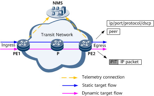
As shown in Figure 1, the iFIT statistical model is composed of three objects: target flows, the transit network, and the measurement system.
-
Target flows are key elements in iFIT statistics. A target flow must be specified before each statistics collection operation. Target flows can be classified as static or dynamic flows based on the generation mode.
- Static flows can be generated in different modes based on the measurement granularity.
- Based on the measurement granularity of 5-tuple, you can specify the related field information, including the 5-tuple (source IP address, destination IP address, protocol number, source port number, and destination port number) and differentiated services code point (DSCP), in an IP packet header to specify static flows. This method can be used to implement performance measurement for specific flows.
- Based on the measurement granularity of the peer IP/peer locator, you can specify a peer IPv4 or IPv6 address to generate a flow. This method can be used to implement performance measurement for E2E traffic.
- iFIT supports automatic learning for dynamic flows on the ingress based on mask matching or exact matching of source/destination addresses. In addition, with iFIT, you can flexibly monitor service quality in real time by configuring a whitelist. The dynamic flows on the transit nodes and the egress are triggered by the traffic with the iFIT header. If the dynamic flow instance does not collect traffic statistics for a long time, it automatically ages.

The default aging time of a dynamic flow instance is 10 times the measurement period, but cannot be less than 10 minutes.
- Static flows can be generated in different modes based on the measurement granularity.
-
The transit network only bears target flows. The target flows are not generated or terminated on the transit network. Each node on the transit network must be reachable at the network layer. The transit network can carry different types of services and tunnels. Table 1 lists the measurement scenarios that support iFIT.
Table 1 Measurement scenarios that support iFIT Service Type
Tunnel Type
Measurement Granularity
L3VPNv4/EVPN L3VPNv4 (HVPN)
MPLS (TE/LDP/BGP LSP/SR-MPLS BE/SR-MPLS TE/SR-MPLS TE Policy)
Measurement based on 5-tuple and DSCP or based on peer IP
SRv6 (SRv6 BE/SRv6 TE Policy)
Measurement based on 5-tuple and DSCP or based on peer locator
L3VPNv6/EVPN L3VPNv6 (HVPN)
MPLS (TE/LDP/BGP LSP/SR-MPLS BE/SR-MPLS TE/SR-MPLS TE Policy)
Measurement based on 5-tuple and DSCP or based on peer IP
L3VPNv6/EVPN L3VPNv6 (HVPN)
SRv6 (SRv6 BE/SRv6 TE Policy)
Measurement based on 5-tuple and DSCP or based on peer locator
EVPN VPWS
MPLS (TE/LDP/BGP LSP/SR-MPLS BE/SR-MPLS TE/SR-MPLS TE Policy)
Measurement based on peer IP
SRv6 (SRv6 BE/SRv6 TE Policy)
Measurement based on peer locator
IPv4 public network
SRv6 (SRv6 BE/SRv6 TE Policy)
Measurement based on 5-tuple and DSCP or based on peer locator
IPv6 public network
SRv6 (SRv6 BE/SRv6 TE Policy)
Measurement based on 5-tuple and DSCP or based on peer locator
The measurement granularities are applicable only to static flow measurement. Dynamic flow measurement is implemented regardless of measurement granularities and is applicable to all the preceding measurement scenarios.
- Measurement systemThe measurement system consists of the ingress (configured with iFIT and iFIT parameters) and multiple iFIT-capable devices. iFIT supports the following two metrics:
- Packet loss rate measurement: Within a measurement interval, the number of lost packets is the difference between the number of packets entering a transit network and the number of packets leaving the transit network.
- Delay measurement: Within a measurement interval, the delay is the time difference between a flow enters and leaves a network.
For details about the measurement indicators, see iFIT Measurement Metrics. The statistics result is sent to the NMS through telemetry for visualized display.
iFIT Header Format
Figure 2 shows the structure of the iFIT header on an MPLS network. Table 2 describes the fields of the iFIT header.

Field |
Description |
|---|---|
Flow Instruction Indicator (FII) |
Reserved label, which can be at the bottom of the stack or not. The default value is 12. |
Flow Instruction Header (FIH) |
|
Flow Instruction Extension Header (FIEH) |
|