Example for Configuring dynamic BGP Flow Specification with a BGP Flow RR
Flow Specification with a Flow RR avoids setup of unnecessary BGP Flow Specification peer relationships.
Networking Requirements
BGP Flow Specification is used to guard against denial-of-service (DoS) and distributed-denial-of-service (DDoS) attacks. Usually, the characteristics of attack traffic are unknown, and in this situation, dynamic BGP Flow Specification needs to be deployed. In an AS with multiple ingresses, a Flow route reflector (Flow RR) can be configured to avoid unnecessary mesh connections between the ingresses and the traffic analysis server. The ingresses and the traffic analysis server functions as clients, and the Flow RR reflects BGP Flow Specification routes generated by the traffic analysis server to the ingresses.
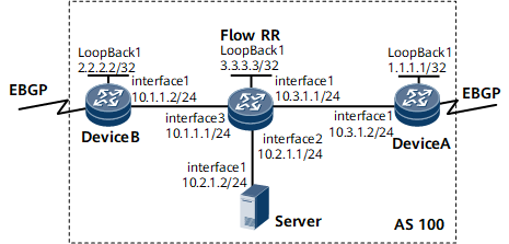
As shown in Figure 1, AS 100 can communicate with other ASs through Device A and Device B. When DoS or DDoS attack traffic flows to AS 100 through Device A and Device B, AS 100 will be congested. In this situation, BGP Flow Specification needs to be deployed. In this networking, use dynamic BGP Flow Specification as an example. Meanwhile, a BGP Flow RR also needs to be deployed to reduce the number of BGP Flow Specification peer relationships maintained on the traffic analysis server and save CPU resources. Configure a Flow RR in AS 100 to reflect BGP Flow Specification routes generated by the traffic analysis server to Device A and Device B so that attack traffic can be controlled.
Configuration Roadmap
The configuration roadmap is as follows:
Connect Flow RR to Device A, Device B, and Server using OSPF.
Establish BGP Flow Specification peer relationships between Flow RR and Device A, Flow RR and Device B, and Flow RR and Server.

A traffic analysis server is a third-party device, and it must function as a BGP Flow Specification peer.
Configure Flow RR as a Flow RR and configure Device A and Device B as clients to enable Flow RR to reflect BGP Flow Specification routes generated by Server to Device A and Device B.
Data Preparation
Router ID of Device A (1.1.1.1), router ID of Device B (2.2.2.2), and router ID of Flow RR (3.3.3.3)
AS numbers of Device A, Device B, Flow RR, and Server: 100
ID of the cluster to which Flow RR belongs: 1
Procedure
- Configure an IP address for each interface.
For detailed configurations, see the configuration files in this example.
- Configure OSPF.
For detailed configurations, see the configuration files in this example.
- Configure BGP Flow Specification peer relationships.
# Configure Device A.
[~DeviceA] bgp 100
[*DeviceA-bgp] router-id 1.1.1.1
[*DeviceA-bgp] peer 3.3.3.3 as-number 100
[*DeviceA-bgp] peer 3.3.3.3 connect-interface LoopBack1
[*DeviceA-bgp] ipv4-family flow
[*DeviceA-bgp-af-ipv4-flow] peer 3.3.3.3 enable
[*DeviceA-bgp-af-ipv4-flow] commit
[~DeviceA-bgp-af-ipv4-flow] quit
[~DeviceA-bgp] quit
# Configure Device B.
[~DeviceB] bgp 100
[*DeviceB-bgp] router-id 2.2.2.2
[*DeviceB-bgp] peer 3.3.3.3 as-number 100
[*DeviceB-bgp] peer 3.3.3.3 connect-interface LoopBack1
[*DeviceB-bgp] ipv4-family flow
[*DeviceB-bgp-af-ipv4-flow] peer 3.3.3.3 enable
[*DeviceB-bgp-af-ipv4-flow] commit
[~DeviceB-bgp-af-ipv4-flow] quit
[~DeviceB-bgp] quit
# Configure Flow RR.
[Flow RR] bgp 100
[Flow RR-bgp] router-id 3.3.3.3
[Flow RR-bgp] peer 1.1.1.1 as-number 100
[Flow RR-bgp] peer 1.1.1.1 connect-interface LoopBack1
[Flow RR-bgp] peer 2.2.2.2 as-number 100
[Flow RR-bgp] peer 2.2.2.2 connect-interface LoopBack1
[Flow RR-bgp] peer 10.2.1.2 as-number 100
[Flow RR-bgp] ipv4-family flow
[Flow RR-bgp-af-ipv4-flow] peer 1.1.1.1 enable
[Flow RR-bgp-af-ipv4-flow] peer 2.2.2.2 enable
[Flow RR-bgp-af-ipv4-flow] peer 10.2.1.2 enable
[Flow RR-bgp-af-ipv4-flow] peer 10.2.1.2 validation-disable
[Flow RR-bgp-af-ipv4-flow] commit
[Flow RR-bgp-af-ipv4-flow] quit
[Flow RR-bgp] quit
- Configure a Flow RR.
# Configure Flow RR.
[Flow RR]bgp 100
[Flow RR-bgp] ipv4-family flow
[Flow RR-bgp-af-ipv4-flow] reflector cluster-id 1
[Flow RR-bgp-af-ipv4-flow] peer 1.1.1.1 reflect-client
[Flow RR-bgp-af-ipv4-flow] peer 2.2.2.2 reflect-client
[Flow RR-bgp-af-ipv4-flow] peer 10.2.1.2 reflect-client
[Flow RR-bgp-af-ipv4-flow] commit
[Flow RR-bgp-af-ipv4-flow] quit
[Flow RR-bgp] quit
- Verify the configuration.
# Check BGP Flow Specification routes received by Device A.
<DeviceA> display bgp flow routing-table
 BGP Local router ID is 1.1.1.1
 Status codes: * - valid, > - best, d - damped, x - best external, a - add path,
               h - history,  i - internal, s - suppressed, S - Stale
               Origin : i - IGP, e - EGP, ? - incomplete
 RPKI validation codes: V - valid, I - invalid, N - not-found

 Total Number of Routes: 1

 * >  ReIndex : 33
      Dissemination Rules:
       Port           : eq 100
       FragmentType   : match (Don't fragment)

       MED      : 0                   PrefVal  : 0
       LocalPref: 100
       Path/Ogn :  i
# Check the traffic policy in each BGP Flow Specification route based on the ReIndex shown in the preceding output.
<DeviceA> display bgp flow routing-table 33
 BGP local router ID : 1.1.1.1
 Local AS number : 100
 ReIndex : 33
 Order   : 2147483647
 Dissemination Rules :
   Port           : eq 100
   FragmentType   : match (Don't fragment)

 BGP flow-ipv4 routing table entry information of 33:
 Match action :
   apply traffic-rate 9600
 From: 3.3.3.3 (3.3.3.3)
 Route Duration: 0d00h16m31s
 AS-path Nil, origin igp, MED 0, localpref 100, pref-val 0, valid, internal, best, pre 255
 Originator: 10.2.1.2
 Cluster list: 0.0.0.1
 Not advertised to any peer yet
The command output shows that Device A has learned a route from Flow RR advertised by Server. Originator and cluster ID are also displayed.
Configuration Files
Device A configuration file
#
sysname DeviceA
#
interface GigabitEthernet0/1/0
 undo shutdown
 ip address 10.3.1.2 255.255.255.0
#
interface LoopBack1
 ip address 1.1.1.1 255.255.255.255
#
bgp 100
 router-id 1.1.1.1
 peer 3.3.3.3 as-number 100
 peer 3.3.3.3 connect-interface LoopBack1
 #
 ipv4-family unicast
  undo synchronization
  peer 3.3.3.3 enable
 #
 ipv4-family flow
  peer 3.3.3.3 enable
#
ospf 1
 area 0.0.0.0
  network 1.1.1.1 0.0.0.0
  network 10.3.1.0 0.0.0.255
#
return
Device B configuration file
#
sysname DeviceB
#
interface GigabitEthernet0/1/0
 undo shutdown
 ip address 10.1.1.2 255.255.255.0
#
interface LoopBack1
 ip address 2.2.2.2 255.255.255.255
#
bgp 100
 router-id 2.2.2.2
 peer 3.3.3.3 as-number 100
 peer 3.3.3.3 connect-interface LoopBack1
 #
 ipv4-family unicast
  undo synchronization
  peer 3.3.3.3 enable
 #
 ipv4-family flow
  peer 3.3.3.3 enable
#
ospf 1
 area 0.0.0.0
  network 2.2.2.2 0.0.0.0
  network 10.1.1.0 0.0.0.255
#
return
Configuration file of Flow RR
#
sysname Flow RR
#
interface GigabitEthernet0/1/0
 undo shutdown
 ip address 10.3.1.1 255.255.255.0
#
interface GigabitEthernet0/1/8
 undo shutdown
 ip address 10.2.1.1 255.255.255.0
#
interface GigabitEthernet0/1/16
 undo shutdown
 ip address 10.1.1.1 255.255.255.0
#
interface LoopBack1
 ip address 3.3.3.3 255.255.255.255
#
bgp 100
 router-id 3.3.3.3
 peer 1.1.1.1 as-number 100
 peer 1.1.1.1 connect-interface LoopBack1
 peer 2.2.2.2 as-number 100
 peer 2.2.2.2 connect-interface LoopBack1
 peer 10.2.1.2 as-number 100
 #
 ipv4-family unicast
  undo synchronization
  peer 1.1.1.1 enable
  peer 2.2.2.2 enable
  peer 10.2.1.2 enable
 #
 ipv4-family flow
  reflector cluster-id 1
  peer 1.1.1.1 enable
  peer 1.1.1.1 reflect-client
  peer 2.2.2.2 enable
  peer 2.2.2.2 reflect-client
  peer 10.2.1.2 enable
  peer 10.2.1.2 reflect-client
  peer 10.2.1.2 validation-disable
#
ospf 1
 area 0.0.0.0
  network 3.3.3.3 0.0.0.0
  network 10.1.1.0 0.0.0.255
  network 10.2.1.0 0.0.0.255
  network 10.3.1.0 0.0.0.255
#
return