Configuring a GMPLS UNI Tunnel
An IP network user can configure a GMPLS UNI tunnel on an edge node for interconnection between the IP network and a transport network, quickly deploying new services and saving operation and maintenance costs.
Usage Scenario
Scenario |
Description |
|---|---|
Rapid service provisioning between the IP and optical layers |
A GMPLS UNI tunneling technology is used to quickly deploy new services and implement interconnection between an IP network and a transport network when a new network is constructed. GMPLS UNI tunnels carry various types of IP or MPLS services. |
SRLG information sharing between the IP and optical layers |
After a GMPLS UNI tunnel is established to connect the IP layer to the optical layer, the ingress EN and CN can advertise SRLG information at the optical layer to all devices at the IP layer. In this situation, when TE FRR or CR-LSP backup is configured at the IP layer, the ingress can use the SRLG information to calculate more accurate backup paths. |

Some GMPLS UNI tunnel configurations need to be performed on edge devices on the transport network. This document mainly describes tunnel configurations on IP network devices. For tunnel configurations of transport network edge devices, see the related configuration guide.
Pre-configuration Tasks
Before configuring a GMPLS UNI tunnel, complete the following tasks:
Enable MPLS-TE and RSVP-TE globally on the ingress EN and egress EN.
(Optional) Configure static routes to ensure that the out-of-band control channel between an IP network and a transport network is reachable at the network layer if the out-of-band mode is used to separate the data channel from the control channel.
(Optional) Enable EFM globally if the in-band mode is used to separate the data channel from the control channel.
Configuration Procedures
- Independent path calculation at IP and optical layers
- PCE path calculation for a path crossing the IP and optical layers
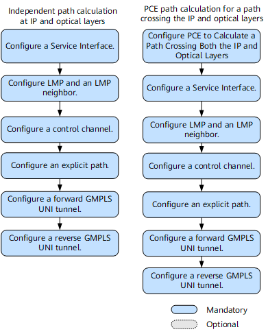
- (Optional) Configuring PCE to Calculate a Path Crossing Both the IP and Optical Layers
- A specific path calculation mode must be planned for a GMPLS UNI tunnel.
- Configuring a Service Interface
- On the NetEngine 8000 F, a logical GMPLS UNI is bound to a GMPLS UNI tunnel so that the logical GMPLS UNI can transmit upper layer services, such as MPLS, IGP, and VPN services, along the GMPLS UNI tunnel.
- Configuring LMP and an LMP Neighbor
- LMP and an LMP neighbor are configured on an edge node on a transport network and an IP network to manage the data and control channels and detect link connectivity.
- Configuring a Control Channel
- A control channel is configured on the ingress EN and egress EN of a GMPLS UNI tunnel to carry GMPLS UNI signaling packets and ensure the normal exchange of GMPLS UNI signaling packets.
- Configuring an Explicit Path
- GMPLS UNI cannot automatically discover paths between an IP network and a transport network. To ensure successful GMPLS UNI establishment, configure an explicit path on the ingress EN to traverse data channel interfaces on the ingress EN, ingress CN, egress EN, and egress CN.
- Configuring a Forward GMPLS UNI Tunnel
- A GMPLS UNI tunnel is unidirectional. A forward GMPLS UNI tunnel and a reverse GMPLS UNI tunnel must be established to implement bidirectional traffic transmission. The ingress EN initiates tunnel establishment requests containing tunnel attributes. Therefore, basic tunnel attributes and functions must be configured on the ingress EN.
- Configuring a Reverse GMPLS UNI Tunnel
- A GMPLS UNI tunnel is unidirectional. After a forward GMPLS UNI tunnel is configured, a reverse GMPLS UNI tunnel must be configured on the egress EN.
- Verifying the GMPLS UNI Tunnel Configuration
- After configuring a GMPLS UNI tunnel, you can view information about the GMPLS UNI tunnel and the tunnel status.