Example for Configuring CEs to Access a VPN Instance Through a GRE Tunnel Traversing VPNs
This section provides an example for configuring a CE to access a VPN through a GRE tunnel traversing another VPN. In this networking scheme, the PE is indirectly connected to the CE; no physical interface can be bound to the VPN instance on the PE. Then, a GRE tunnel traversing a VPN is required between the CE and PE and the GRE tunnel needs to be bound to the VPN instance on the PE. This allows the CE to access the VPN through the GRE tunnel.
Networking Requirements
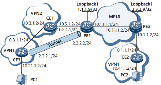
As Figure1 Networking diagram in which CEs access the VPN through the GRE tunnel that traverses VPNs shows:
PE1 and PE2 are located on the first-level carrier's MPLS backbone network.
VPN2 is a second-level carrier's VPN. CE1 in VPN2 is directly connected to PE1.
CE2 and CE3, both belonging to vpn1, are customer's devices. CE2 is directly connected to PE2, and CE3 is directly connected to CE1.
CE2 and CE3 are required to interwork with each other.
Device Name |
Interface |
IP Address |
CE3 |
GE 0/1/0 |
10.21.1.2/24 |
CE3 |
GE 0/1/8 |
10.3.1.1/24 |
CE3 |
Tunnel2 |
2.2.2.1/24 |
CE3 |
Loopback1 |
5.5.5.9/32 |
CE1 |
GE 0/1/0 |
10.3.1.2/24 |
CE1 |
GE 0/1/8 |
10.5.1.1/24 |
PE1 |
Loopback1 |
1.1.1.9/32 |
PE1 |
Loopback0 |
4.4.4.9/32 |
PE1 |
GE 0/1/0 |
10.5.1.2/24 |
PE1 |
GE 0/1/8 |
10.11.1.1/24 |
PE1 |
Tunnel1 |
2.2.2.2/24 |
PE2 |
Loopback1 |
3.3.3.9/32 |
PE2 |
GE 0/1/0 |
10.11.1.2/24 |
PE2 |
GE 0/1/8 |
10.1.1.2/24 |
CE2 |
GE 0/1/0 |
10.1.1.1/24 |
CE2 |
GE 0/1/8 |
10.41.1.2/24 |
Configuration Roadmap
PE1 and CE3 are indirectly connected. So the VPN instance on PE1 cannot be bound to the physical interface on PE1. In such a situation, a GRE tunnel is required between CE3 and PE1. vpn1 on PE1 can then be bound to the GRE tunnel, and CE3 can access the VPN through the GRE tunnel.
The configuration roadmap is as follows:
Configure OSPF10 on the Level 1 carrier's backbone network routers, namely, PE1 and PE2. In this manner, PE1 and PE2 can interwork with each other. Then enable MPLS.
Configure VPN2 on PE1. Then configure OSPF20 on PE1, CE1, and CE3 to realize the interworking between the three devices.
Establish a GRE tunnel between CE3 and PE1. Note that PE1 is connected to CE3 through VPN2. So the interfaces directly connecting CE3 and CE1 and the interfaces directly connecting PE1 and CE1 all belong to VPN2. In addition, when the GRE tunnel is established on PE1, the specified destination address of the GRE tunnel must belong to VPN2.
Create the VPN instance named vpn1 on PE1 and PE2, bind vpn1 on PE1 to the GRE tunnel interface, and bind vpn1 on PE2 to the connected physical interface of CE2.
Configure IS-IS routes between CE2 and PE2, and between CE3 and its PE1 to implement the interworking between the CEs and PEs.
Configure BGP on PEs to implement the interworking between CE2 and CE3.
Data Preparation
To complete the configuration, you need the following data:
IP addresses of the interfaces, process ID of the routing protocol, and AS number
Source address and destination address of the GRE tunnel
VPN instance names, RDs, and VPN targets on PEs
Procedure
- Configure the IP address for each interface
# Configure CE3.
<HUAWEI> system-view
[~HUAWEI] sysname CE3
[*HUAWEI] commit
[~CE3] vlan batch 10 20
[*CE3] interface gigabitethernet 0/1/0
[*CE3-GigabitEthernet0/1/0] undo shudown
[*CE3-GigabitEthernet0/1/0] portswitch
[*CE3-GigabitEthernet0/1/0] port link-type hybrid
[*CE3-GigabitEthernet0/1/0] port default vlan 10
[*CE3-GigabitEthernet0/1/0] quit
[*CE3] interface gigabitethernet 0/1/8
[*CE3-GigabitEthernet0/1/8] undo shudown
[*CE3-GigabitEthernet0/1/8] portswitch
[*CE3-GigabitEthernet0/1/8] port link-type hybrid
[*CE3-GigabitEthernet0/1/8] port default vlan 20
[*CE3-GigabitEthernet0/1/8] quit
[*CE3] interface vlanif 10
[*CE3-Vlanif10] ip address 10.21.1.2 24
[*CE3-Vlanif10] quit
[*CE3] interface vlanif 20
[*CE3-Vlanif20] ip address 10.3.1.1 24
[*CE3-Vlanif20] quit
[*CE3] interface loopback1
[*CE3-LoopBack1] ip address 5.5.5.9 32
[*CE3-LoopBack1] quit
[*CE3] commit
# Configure CE1.
<HUAWEI> system-view
[~HUAWEI] sysname CE1
[*HUAWEI] commit
[~CE1] vlan batch 10 20
[*CE1] interface gigabitethernet 0/1/0
[*CE1-GigabitEthernet0/1/0] undo shudown
[*CE1-GigabitEthernet0/1/0] portswitch
[*CE1-GigabitEthernet0/1/0] port link-type hybrid
[*CE1-GigabitEthernet0/1/0] port default vlan 20
[*CE1-GigabitEthernet0/1/0] quit
[*CE1] interface gigabitethernet 0/1/8
[*CE1-GigabitEthernet0/1/8] undo shudown
[*CE1-GigabitEthernet0/1/8] portswitch
[*CE1-GigabitEthernet0/1/8] port link-type hybrid
[*CE1-GigabitEthernet0/1/8] port default vlan 10
[*CE1-GigabitEthernet0/1/8] quit
[*CE1] interface vlanif 10
[*CE1-Vlanif10] ip address 10.3.1.2 24
[*CE1-Vlanif10] quit
[*CE1] interface vlanif 20
[*CE1-Vlanif20] ip address 10.5.1.1 24
[*CE1-Vlanif20] quit
[*CE1] commit
# Configure IP addresses for interfaces on PE1 except the interface to be bound with a VPN instance, because all configurations on this interface are deleted when the interface is bound to a VPN instance.
<HUAWEI> system-view
[~HUAWEI] sysname PE1
[*HUAWEI] commit
[~PE1] vlan batch 10 20
[*PE1] interface gigabitethernet 0/1/0
[*PE1-GigabitEthernet0/1/0] undo shudown
[*PE1-GigabitEthernet0/1/0] portswitch
[*PE1-GigabitEthernet0/1/0] port link-type hybrid
[*PE1-GigabitEthernet0/1/0] port default vlan 10
[*PE1-GigabitEthernet0/1/0] quit
[*PE1] interface gigabitethernet 0/1/8
[*PE1-GigabitEthernet0/1/8] undo shudown
[*PE1-GigabitEthernet0/1/8] portswitch
[*PE1-GigabitEthernet0/1/8] port link-type hybrid
[*PE1-GigabitEthernet0/1/8] port default vlan 20
[*PE1-GigabitEthernet0/1/8] quit
[*PE1] interface vlanif 20
[*PE1-Vlanif20] ip address 10.11.1.1 24
[*PE1-Vlanif20] quit
[*PE1] interface loopback 1
[*PE1-LoopBack1] ip address 1.1.1.9 32
[*PE1-LoopBack1] quit
[*PE1] commit
# Configure IP addresses for interfaces on PE2 except the interface to be bound with a VPN instance, because all configurations on this interface are deleted when the interface is bound to a VPN instance.
<HUAWEI> system-view
[~HUAWEI] sysname PE2
[*HUAWEI] commit
[~PE2] vlan batch 10 20
[*PE2] interface gigabitethernet 0/1/0
[*PE2-GigabitEthernet0/1/0] undo shudown
[*PE2-GigabitEthernet0/1/0] portswitch
[*PE2-GigabitEthernet0/1/0] port link-type hybrid
[*PE2-GigabitEthernet0/1/0] port default vlan 20
[*PE2-GigabitEthernet0/1/0] quit
[*PE2] interface gigabitethernet 0/1/8
[*PE2-GigabitEthernet0/1/8] undo shudown
[*PE2-GigabitEthernet0/1/8] portswitch
[*PE2-GigabitEthernet0/1/8] port link-type hybrid
[*PE2-GigabitEthernet0/1/8] port default vlan 10
[*PE2-GigabitEthernet0/1/8] quit
[*PE2] interface vlanif 20
[*PE2-Vlanif10] ip address 10.11.1.2 24
[*PE2-Vlanif10] quit
[*PE2] interface loopback 1
[*PE2-LoopBack1] ip address 3.3.3.9 32
[*PE2-LoopBack1] quit
[*PE2] commit
# Configure CE2.
<HUAWEI> system-view
[~HUAWEI] sysname CE2
[*HUAWEI] commit
[~CE2] vlan batch 10 20
[*CE2] interface gigabitethernet 0/1/0
[*CE2-GigabitEthernet0/1/0] undo shudown
[*CE2-GigabitEthernet0/1/0] portswitch
[*CE2-GigabitEthernet0/1/0] port link-type hybrid
[*CE2-GigabitEthernet0/1/0] port default vlan 10
[*CE2-GigabitEthernet0/1/0] quit
[*CE2] interface gigabitethernet 0/1/8
[*CE2-GigabitEthernet0/1/8] undo shudown
[*CE2-GigabitEthernet0/1/8] portswitch
[*CE2-GigabitEthernet0/1/8] port link-type hybrid
[*CE2-GigabitEthernet0/1/8] port default vlan 20
[*CE2-GigabitEthernet0/1/8] quit
[*CE2] interface vlanif 10
[*CE2-Vlanif10] ip address 10.1.1.1 24
[*CE2-Vlanif10] quit
[*CE2] interface vlanif 20
[*CE2-Vlanif20] ip address 10.41.1.2 24
[*CE2-Vlanif20] quit
[*CE2] commit
- Configure a routing protocol on the PEs on the backbone network to implement interworking and enable MPLS.
# On PE1, enable MPLS LDP, and run OSPF process 10 to configure reachable routes between PEs. LSPs are set up automatically.
[*PE1] mpls lsr-id 1.1.1.9
[*PE1] mpls
[*PE1-mpls] lsp-trigger all
[*PE1-mpls] quit
[*PE1] mpls ldp
[*PE1-mpls-ldp] quit
[*PE1] ospf 10
[*PE1-ospf-10] area 0
[*PE1-ospf-10-area-0.0.0.0] network 1.1.1.9 0.0.0.0
[*PE1-ospf-10-area-0.0.0.0] network 10.11.1.0 0.0.0.255
[*PE1-ospf-10-area-0.0.0.0] quit
[*PE1-ospf-10] quit
[*PE1] interface vlanif 20
[*PE1-Vlanif20] mpls
[*PE1-Vlanif20] mpls ldp
[*PE1-Vlanif20] quit
[*PE1] commit
# On PE2, enable MPLS LDP, and run OSPF process 10 to configure reachable routes between PEs. LSPs are set up automatically.
[*PE2] mpls lsr-id 3.3.3.9
[*PE2] mpls
[*PE2-mpls] lsp-trigger all
[*PE2-mpls] quit
[*PE2] mpls ldp
[*PE2-mpls-ldp] quit
[*PE2] ospf 10
[*PE2-ospf-10] area 0
[*PE2-ospf-10-area-0.0.0.0] network 3.3.3.9 0.0.0.0
[*PE2-ospf-10-area-0.0.0.0] network 10.11.1.0 0.0.0.255
[*PE2-ospf-10-area-0.0.0.0] quit
[*PE2-ospf-10] quit
[*PE2] interface vlanif 10
[*PE2-Vlanif10] mpls
[*PE2-Vlanif10] mpls ldp
[*PE2-Vlanif10] quit
[*PE2] commit
- Configure a VPN instance named VPN2 on PE1 and configure a routing protocol on PE1, CE1, and CE3.
# Configure VPN2 and OSPF20 on PE1.
[*PE1] ip vpn-instance vpn2
[*PE1-vpn-instance-vpn2] route-distinguisher 100:2
[*PE1-vpn-instance-vpn2] vpn-target 222:2 export-extcommunity
[*PE1-vpn-instance-vpn2] vpn-target 222:2 import-extcommunity
[*PE1-vpn-instance-vpn2] quit
[*PE1] interface vlanif 10
[*PE1-Vlanif10] ip binding vpn-instance vpn2
[*PE1-Vlanif10] ip address 10.5.1.2 24
[*PE1-Vlanif10] quit
[~PE1] interface loopback0
[*PE1-LoopBack0] ip binding vpn-instance vpn2
[*PE1-LoopBack0] ip address 4.4.4.9 255.255.255.255
[*PE1-LoopBack0] binding tunnel gre
[*PE1] ospf 20 vpn-instance vpn2
[*PE1-ospf-20] area 0
[*PE1-ospf-20-area-0.0.0.0] network 10.5.1.0 0.0.0.255
[*PE1-ospf-20-area-0.0.0.0] network 4.4.4.9 0.0.0.0
[*PE1-ospf-20-area-0.0.0.0] quit
[*PE1-ospf-20] quit
[*PE1] commit
# Configure OSPF20 between CE1 and CE3 to implement the interworking between PE1, CE1, and CE3. The detailed configurations are not mentioned here.
- Establish a GRE tunnel between CE3 and PE1.
# Configure CE3.
[~CE3] interface loopback1
[*CE3-LoopBack1] binding tunnel gre
[*CE3-LoopBack1] commit
[~CE3-LoopBack1] quit
[*CE3] interface Tunnel2
[*CE3-Tunnel2] ip address 2.2.2.1 255.255.255.0
[*CE3-Tunnel2] tunnel-protocol gre
[*CE3-Tunnel2] source 5.5.5.9
[*CE3-Tunnel2] destination 4.4.4.9
[*CE3-Tunnel2] quit
[*CE3] commit
# Configure PE1.
[~PE1] interface loopback0
[*PE1-LoopBack0] binding tunnel gre
[*PE1-LoopBack0] commit
[~PE1-LoopBack0] quit
[*PE1] interface Tunnel1
[*PE1-Tunnel1] ip address 2.2.2.2 255.255.255.0
[*PE1-Tunnel1] tunnel-protocol gre
[*PE1-Tunnel1] source 4.4.4.9
[*PE1-Tunnel1] destination vpn-instance vpn2 5.5.5.9
[*PE1-Tunnel1] quit
[*PE1] commit

The specified destination tunnel address must belong to VPN2 because the GRE tunnel between PE1 and CE3 traverses VPN2.
# After the configuration, a GRE tunnel is established between CE3 and PE1.
- Create vpn1 on PE1 and bind the instance to the GRE tunnel.
[*PE1]ip vpn-instance vpn1
[*PE1-vpn-instance-vpn1] route-distinguisher 100:1
[*PE1-vpn-instance-vpn1] vpn-target 111:1 export-extcommunity
[*PE1-vpn-instance-vpn1] vpn-target 111:1 import-extcommunity
[*PE1-vpn-instance-vpn1] quit
[*PE1] interfacet Tunnel1
[*PE1-Tunnel1] ip binding vpn-instance vpn1
[*PE1-Tunnel1] ip address 2.2.2.2 255.255.255.0
[*PE1-Tunnel1] quit
[*PE1] commit
- Create a VPN instance named vpn1 on PE2 and bind the VPN instance to the VLANIF interface.
[*PE2]ip vpn-instance vpn1
[*PE2-vpn-instance-vpn1] route-distinguisher 200:1
[*PE2-vpn-instance-vpn1] vpn-target 111:1 export-extcommunity
[*PE2-vpn-instance-vpn1] vpn-target 111:1 import-extcommunity
[*PE2-vpn-instance-vpn1] quit
[*PE2] interface vlanif 20
[*PE2-Vlanif20] ip binding vpn-instance vpn1
[*PE2-Vlanif20] ip address 10.1.1.2 255.255.255.0
[*PE2-Vlanif20] undo shutdown
[*PE2-Vlanif20] quit
[*PE2] commit
- Configure IS-IS routes between CE3 and PE1.
# Configure CE3.
[*CE3] isis 50
[*CE3-isis-50] network-entity 50.0000.0000.0001.00
[*CE3-isis-50] quit
[*CE3] interface vlanif 10
[*CE3-Vlanif10] isis enable 50
[*CE3-Vlanif10] quit
[*CE3] interface Tunnel2
[*CE3-Tunnel2] isis enable 50
[*CE3-Tunnel2] quit
[*CE3] commit
# Configure PE1.
[*PE1] isis 50 vpn-instance vpn1
[*PE1-isis-50] network-entity 50.0000.0000.0002.00
[*PE1-isis-50] quit
[*PE1] interface Tunnel1
[*PE1-Tunnel1] isis enable 50
[*PE1-Tunnel1] quit
[*PE1] commit
- Configure IS-IS routes between CE2 and PE2.
# Configure CE2.
[*CE2] isis 50
[*CE2-isis-50] network-entity 50.0000.0000.0004.00
[*CE2-isis-50] quit
[*CE2] interface vlanif 10
[*CE2-Vlanif10] isis enable 50
[*CE2-Vlanif10] quit
[*CE2] interface vlanif 20
[*CE2-Vlanif20] isis enable 50
[*CE2-Vlanif20] quit
[*CE2] commit
# Configure PE2.
[*PE2] isis 50 vpn-instance vpn1
[*PE2-isis-50] network-entity 50.0000.0000.0003.00
[*PE2-isis-50] quit
[*PE2] interface vlanif 10
[*PE2-Vlanif10] isis enable 50
[*PE2-Vlanif10] quit
[*PE2] commit
- Set up the MP IBGP peer relationship between PEs.
# On PE1, specify PE2 as an IBGP peer, set up the IBGP connection by using the loopback interface, and enable the capability of exchanging VPN IPv4 routing information between PE1 and PE2.
[*PE1] bgp 100
[*PE1-bgp] peer 3.3.3.9 as-number 100
[*PE1-bgp] peer 3.3.3.9 connect-interface loopback 1
[*PE1-bgp] ipv4-family vpnv4
[*PE1-bgp-af-vpnv4] peer 3.3.3.9 enable
[*PE1-bgp-af-vpnv4] quit
[*PE1-bgp] commit
# Enter the view of the BGP VPN instance vpn1 and import the direct routes and IS-IS routes.
[*PE1-bgp] ipv4-family vpn-instance vpn1
[*PE1-bgp-vpn1] import-route isis 50
[*PE1-bgp-vpn1] import-route ospf 20
[*PE1-bgp-vpn1] commit
[*PE1-bgp-vpn1] quit
[*PE1-bgp] quit
# On PE2, specify PE1 as an IBGP peer, set up the IBGP connection by using the loopback interface, and enable the capability of exchanging VPN IPv4 routing information between PE2 and PE1.
[*PE2] bgp 100
[*PE2-bgp] peer 1.1.1.9 as-number 100
[*PE2-bgp] peer 1.1.1.9 connect-interface loopback 1
[*PE2-bgp] ipv4-family vpnv4
[*PE2-bgp-af-vpnv4] peer 1.1.1.9 enable
[*PE2-bgp-af-vpnv4] quit
[*PE2-bgp] commit
# Enter the view of the BGP VPN instance vpn1 and import the direct routes and IS-IS routes.
[*PE2-bgp] ipv4-family vpn-instance vpn1
[*PE2-bgp-vpn1] import-route isis 50
[*PE2-bgp-vpn1] commit
[*PE2-bgp-vpn1] quit
[*PE2-bgp] quit
- Import BGP routes into IS-IS.
# Configure PE1.
[*PE1] isis 50
[*PE1-isis-50] import-route bgp
[*PE1-isis-50] commit
# Configure PE2.
[*PE2] isis 50
[*PE2-isis-50] import-route bgp
[*PE2-isis-50] commit
- Verify the configuration.
# After the configuration, CE2 and CE3 can successfully ping each other.
<CE3> ping 10.41.1.2
  PING 10.41.1.2: 56  data bytes, press CTRL_C to break
    Reply from 10.41.1.2: bytes=56 Sequence=1 ttl=253 time=160 ms
    Reply from 10.41.1.2: bytes=56 Sequence=2 ttl=253 time=90 ms
    Reply from 10.41.1.2: bytes=56 Sequence=3 ttl=253 time=160 ms
    Reply from 10.41.1.2: bytes=56 Sequence=4 ttl=253 time=100 ms
    Reply from 10.41.1.2: bytes=56 Sequence=5 ttl=253 time=160 ms

  --- 10.41.1.2 ping statistics ---
    5 packet(s) transmitted
    5 packet(s) received
    0.00% packet loss
    round-trip min/avg/max = 90/134/160 ms

<CE2> ping 10.21.1.2
  PING 10.21.1.2: 56  data bytes, press CTRL_C to break
    Reply from 10.21.1.2: bytes=56 Sequence=1 ttl=253 time=440 ms
    Reply from 10.21.1.2: bytes=56 Sequence=2 ttl=253 time=100 ms
    Reply from 10.21.1.2: bytes=56 Sequence=3 ttl=253 time=100 ms
    Reply from 10.21.1.2: bytes=56 Sequence=4 ttl=253 time=120 ms
    Reply from 10.21.1.2: bytes=56 Sequence=5 ttl=253 time=120 ms

  --- 10.21.1.2 ping statistics ---
    5 packet(s) transmitted
    5 packet(s) received
    0.00% packet loss
    round-trip min/avg/max = 100/176/440 ms
Configuration Files
Configuration file of CE3
#
sysname CE3
#
vlan batch 10 20
#
isis 50
 network-entity 50.0000.0000.0001.00
#
interface Vlanif10
 ip address 10.21.1.2 255.255.255.0
 isis enable 50
#
interface Vlanif20
 ip address 10.3.1.1 255.255.255.0
#
interface GigabitEthernet0/1/0
 portswitch
 undo shutdown
 port default vlan 10
#
interface GigabitEthernet0/1/8
 portswitch
 undo shutdown
 port default vlan 20
#
interface LoopBack1
 ip address 5.5.5.9 255.255.255.255
 binding tunnel gre
#
interface Tunnel2
 ip address 2.2.2.1 255.255.255.0
 tunnel-protocol gre
 source 5.5.5.9
 destination 4.4.4.9
 isis enable 50
#
ospf 20
 area 0.0.0.0
  network 5.5.5.9 0.0.0.0
  network 10.3.1.0 0.0.0.255
#
return
Configuration file of CE1
#
sysname CE1
#
vlan batch 10 20
#
interface Vlanif10
 ip address 10.5.1.1 255.255.255.0
#
interface Vlanif20
 ip address 10.3.1.2 255.255.255.0
#
interface GigabitEthernet0/1/0
 portswitch
 undo shutdown
 port default vlan 20
#
interface GigabitEthernet0/1/8
 portswitch
 undo shutdown
 port default vlan 10
#
ospf 20
 area 0.0.0.0
  network 10.3.1.0 0.0.0.255
  network 10.5.1.0 0.0.0.255
#
return
Configuration file of PE1
#
sysname PE1
#
vlan batch 10 20
#
ip vpn-instance vpn1
 ipv4-family
  route-distinguisher 100:1
  apply-label per-instance
  vpn-target 111:1 export-extcommunity
  vpn-target 111:1 import-extcommunity
#
ip vpn-instance vpn2
 ipv4-family
  route-distinguisher 100:2
  apply-label per-instance
  vpn-target 222:2 export-extcommunity
  vpn-target 222:2 import-extcommunity
#
mpls lsr-id 4.4.4.9
#
mpls
 lsp-trigger all
#
mpls ldp
#
isis 50 vpn-instance vpn1
 network-entity 50.0000.0000.0002.00
 import-route bgp
#
interface Vlanif10
 ip binding vpn-instance vpn2
 ip address 10.5.1.2 255.255.255.0
#
interface Vlanif20
 ip address 10.11.1.1 255.255.255.0
 mpls
 mpls ldp
#
interface GigabitEthernet0/1/0
 portswitch
 undo shutdown
 port default vlan 10
#
interface GigabitEthernet0/1/8
 portswitch
 undo shutdown
 port default vlan 20
#
interface LoopBack0
 ip binding vpn-instance vpn2
 ip address 4.4.4.9 255.255.255.255
 binding tunnel gre
#
interface Tunnel1
 ip binding vpn-instance vpn1
 ip address 2.2.2.2 255.255.255.0
 tunnel-protocol gre
 source 4.4.4.9
 destination vpn-instance vpn2 5.5.5.9
 isis enable 50
#
bgp 100
 peer 3.3.3.9 as-number 100
 peer 3.3.3.9 connect-interface LoopBack1
 #
 ipv4-family unicast
  undo synchronization
  peer 3.3.3.9 enable
 #
 ipv4-family vpnv4
  policy vpn-target
  peer 3.3.3.9 enable
 #
 ipv4-family vpn-instance vpn1
  import-route ospf 20
  import-route isis 50
#
ospf 10
 area 0.0.0.0
  network 4.4.4.9 0.0.0.0
  network 10.11.1.0 0.0.0.255
#
ospf 20 vpn-instance vpn2
 area 0.0.0.0
  network 4.4.4.9 0.0.0.0
  network 10.5.1.0 0.0.0.255
#
return
Configuration file of PE2
#
sysname PE2
#
vlan batch 10 20
#
ip vpn-instance vpn1
 ipv4-family
  route-distinguisher 200:1
  apply-label per-instance
  vpn-target 111:1 export-extcommunity
  vpn-target 111:1 import-extcommunity
#
mpls lsr-id 3.3.3.9
#
mpls
 lsp-trigger all
#
mpls ldp
#
isis 50 vpn-instance vpn1
 network-entity 50.0000.0000.0003.00
 import-route bgp
#
interface Vlanif10
 ip binding vpn-instance vpn1
 ip address 10.1.1.2 255.255.255.0
 isis enable 50
#
interface Vlanif20
 ip address 10.11.1.2 255.255.255.0
 mpls
 mpls ldp
#
interface GigabitEthernet0/1/0
 portswitch
 undo shutdown
 port default vlan 20
#
interface GigabitEthernet0/1/8
 portswitch
 undo shutdown
 port default vlan 10
#
interface LoopBack1
 ip address 3.3.3.9 255.255.255.255
#
bgp 100
 peer 1.1.1.9 as-number 100
 peer 1.1.1.9 connect-interface LoopBack1
 #
 ipv4-family unicast
  undo synchronization
  peer 1.1.1.9 enable
 #
 ipv4-family vpnv4
  policy vpn-target
  peer 1.1.1.9 enable
 #
 ipv4-family vpn-instance vpn1
  import-route isis 50
#
ospf 10
 area 0.0.0.0
  network 3.3.3.9 0.0.0.0
  network 10.11.1.0 0.0.0.255
#
return
Configuration file of CE2
#
sysname CE2
#
vlan batch 10 20
#
isis 50
 network-entity 50.0000.0000.0004.00
#
interface Vlanif10
 ip address 10.1.1.1 255.255.255.0
 isis enable 50
#
interface Vlanif20
 ip address 10.41.1.2 255.255.255.0
 isis enable 50
#
interface GigabitEthernet0/1/0
 portswitch
 undo shutdown
 port default vlan 10
#
interface GigabitEthernet0/1/8
 portswitch
 undo shutdown
 port default vlan 20
#
return