Example for Configuring the Keepalive Function for GRE
This section provides an example for configuring the Keepalive function of the GRE tunnel. In this manner, the VPN does not select the GRE tunnel that cannot reach the remote end, and data loss can be avoided.
Networking Requirements
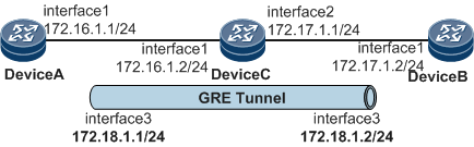
As shown in Figure 1, Device A and Device B are configured with the GRE protocol. The two ends of the GRE tunnel need be configured with the Keepalive function.
Configuration Roadmap
To enable the Keepalive function on one end of the GRE tunnel, run the keepalive command in the tunnel interface view on the end.

If the Keepalive function is enabled on the source end, the forwarding function is mandatory on the destination end and the Keepalive function is optional.
Data Preparation
To complete the configuration, you need the following data:
Data for configuring the routing protocol for the backbone network
Source address and destination address of the GRE tunnel
Interval for sending Keepalive messages
Parameters of an unreachable timer
Procedure
- Configure the routing protocol for the backbone network to implement the interworking between Device A and Device B.
# Configure DeviceA.
<HUAWEI> system-view
[~HUAWEI] sysname DeviceA
[*HUAWEI] commit
[~DeviceA] vlan 10
[*DeviceA-vlan10] quit
[*DeviceA] interface GigabitEthernet 0/1/0
[*DeviceA-GigabitEthernet0/1/0] undo shutdown
[*DeviceA-GigabitEthernet0/1/0] portswitch
[*DeviceA-GigabitEthernet0/1/0] port link-type hybrid
[*DeviceA-GigabitEthernet0/1/0] port default vlan 10
[*DeviceA-GigabitEthernet0/1/0] quit
[*DeviceA] interface vlanif 10
[*DeviceA-Vlanif10] ip address 172.16.1.1 24
[*DeviceA-Vlanif10] quit
[*DeviceA] interface loopback1
[*DeviceA-LoopBack1] ip address 1.1.1.9 32
[*DeviceA-LoopBack1] commit
[~DeviceA-LoopBack1] quit
[*DeviceA] ospf 1
[*DeviceA-ospf-1] area 0
[*DeviceA-ospf-1-area-0.0.0.0] network 172.16.1.0 0.0.0.255
[*DeviceA-ospf-1-area-0.0.0.0] network 1.1.1.9 0.0.0.0
[*DeviceA-ospf-1-area-0.0.0.0] quit
[*DeviceA-ospf-1] quit
[*DeviceA] commit
# Configure DeviceB.
<HUAWEI> system-view
<HUAWEI> system-view
[~HUAWEI] sysname DeviceB
[*HUAWEI] commit
[~DeviceB] vlan 20
[*DeviceB-vlan20] quit
[*DeviceB] interface GigabitEthernet 0/1/0
[*DeviceB-GigabitEthernet0/1/0] undo shutdown
[*DeviceB-GigabitEthernet0/1/0] portswitch
[*DeviceB-GigabitEthernet0/1/0] port link-type hybrid
[*DeviceB-GigabitEthernet0/1/0] port default vlan 20
[*DeviceB-GigabitEthernet0/1/0] quit
[*DeviceB] interface vlanif 20
[*DeviceB-Vlanif20] ip address 172.17.1.2 24
[*DeviceB-Vlanif20] quit
[*DeviceB] interface loopback1
[*DeviceB-LoopBack1] ip address 2.2.2.9 32
[*DeviceB-LoopBack1] commit
[~DeviceB-LoopBack1] quit
[*DeviceB] ospf 1
[*DeviceB-ospf-1] area 0
[*DeviceB-ospf-1-area-0.0.0.0] network 172.17.1.0 0.0.0.255
[*DeviceB-ospf-1-area-0.0.0.0] network 2.2.2.9 0.0.0.0
[*DeviceB-ospf-1-area-0.0.0.0] quit
[*DeviceB-ospf-1] quit
[*DeviceB] commit
# Configure DeviceC.
<HUAWEI> system-view
[~HUAWEI] sysname DeviceC
[*HUAWEI] commit
[~DeviceC] vlan batch 10 20
[*DeviceC-vlan20] quit
[*DeviceC] interface GigabitEthernet 0/1/0
[*DeviceC-GigabitEthernet0/1/0] undo shutdown
[*DeviceC-GigabitEthernet0/1/0] portswitch
[*DeviceC-GigabitEthernet0/1/0] port link-type hybrid
[*DeviceC-GigabitEthernet0/1/0] port default vlan 10
[*DeviceC-GigabitEthernet0/1/0] quit
[*DeviceC] interface GigabitEthernet 0/1/8
[*DeviceC-GigabitEthernet0/1/8] undo shutdown
[*DeviceC-GigabitEthernet0/1/8] portswitch
[*DeviceC-GigabitEthernet0/1/8] port link-type hybrid
[*DeviceC-GigabitEthernet0/1/8] port default vlan 20
[*DeviceC-GigabitEthernet0/1/8] quit
[*DeviceC] interface vlanif 10
[*DeviceC-Vlanif10] ip address 172.16.1.2 24
[*DeviceC-Vlanif10] quit
[*DeviceC] interface vlanif 20
[*DeviceC-Vlanif20] ip address 172.17.1.1 24
[*DeviceC-Vlanif20] quit
[*DeviceC] ospf 1
[*DeviceC-ospf-1] area 0
[*DeviceC-ospf-1-area-0.0.0.0] network 172.16.1.0 0.0.0.255
[*DeviceC-ospf-1-area-0.0.0.0] network 172.17.1.0 0.0.0.255
[*DeviceC-ospf-1-area-0.0.0.0] quit
[*DeviceC-ospf-1] quit
[*DeviceC] commit
- Configure a tunnel on Device A and enable the Keepalive function.
[~DeviceA] interface loopback1
[*DeviceA-LoopBack1] binding tunnel gre
[*DeviceA-LoopBack1] commit
[~DeviceA-LoopBack1] quit
[~DeviceA] interface tunnel 1
[*DeviceA-Tunnel1] ip address 172.18.1.1 255.255.255.0
[*DeviceA-Tunnel1] tunnel-protocol gre
[*DeviceA-Tunnel1] source 1.1.1.9
[*DeviceA-Tunnel1] destination 2.2.2.9
[*DeviceA-Tunnel1] keepalive period 20 retry-times 3
[*DeviceA-Tunnel1] quit
[*DeviceA] commit
- Configure a tunnel on Device B and enable the Keepalive function.
[~DeviceB] interface loopback1
[*DeviceB-LoopBack1] binding tunnel gre
[*DeviceB-LoopBack1] commit
[~DeviceB-LoopBack1] quit
[~DeviceB] interface tunnel 1
[*DeviceB-Tunnel1] ip address 172.18.1.2 255.255.255.0
[*DeviceB-Tunnel1] tunnel-protocol gre
[*DeviceB-Tunnel1] source 2.2.2.9
[*DeviceB-Tunnel1] destination 1.1.1.9
[*DeviceB-Tunnel1] keepalive period 20 retry-times 3
[*DeviceB-Tunnel1] quit
[*DeviceB] commit
- Verify the configuration.
# The tunnel interface on Device A can successfully ping the tunnel interface on Device B.
[~DeviceA] ping -a 172.18.1.1 172.18.1.2
  PING 172.18.1.2: 56  data bytes, press CTRL_C to break
    Reply from 172.18.1.2: bytes=56 Sequence=1 ttl=255 time=9 ms
    Reply from 172.18.1.2: bytes=56 Sequence=2 ttl=255 time=5 ms
    Reply from 172.18.1.2: bytes=56 Sequence=3 ttl=255 time=5 ms
    Reply from 172.18.1.2: bytes=56 Sequence=4 ttl=255 time=6 ms
    Reply from 172.18.1.2: bytes=56 Sequence=5 ttl=255 time=6 ms

  --- 172.18.1.2 ping statistics ---
    5 packet(s) transmitted
    5 packet(s) received
    0.00% packet loss
    round-trip min/avg/max = 5/6/9 ms
# Check information about the Keepalive messages under the Tunnel interface view on Device A.
[~DeviceA] interface tunnel 1
[~DeviceA-Tunnel1] display keepalive packets count
Send 7 keepalive packets to peers, Receive 7 keepalive response packets from peers
Receive 0 keepalive packets from peers, Send 0 keepalive response packets to peers.
Configuration Files
Configuration file of Device A
#
sysname DeviceA
#
vlan batch 10
#
interface Vlanif10
 ip address 172.16.1.1 255.255.255.0
#
interface GigabitEthernet 0/1/0
 portswitch
 undo shutdown
 port default vlan 10
#
interface LoopBack1
 ip address 1.1.1.9 255.255.255.255
 binding tunnel gre
#
interface Tunnel1
 ip address 172.18.1.1 255.255.255.0
 tunnel-protocol gre
 keepalive period 20
 source 1.1.1.9
 destination 2.2.2.9
#
ospf 1
 area 0.0.0.0
  network 1.1.1.9 0.0.0.0
  network 172.16.1.0 0.0.0.255
#
return
Configuration file of Device B
#
sysname DeviceB
#
vlan batch 20
#
interface Vlanif20
 ip address 172.17.1.2 255.255.255.0
#
interface GigabitEthernet 0/1/0
 portswitch
 undo shutdown
 port default vlan 20
#
interface LoopBack1
 ip address 2.2.2.9 255.255.255.0
 binding tunnel gre
#
interface Tunnel1
 ip address 172.18.1.2 255.255.255.0
 tunnel-protocol gre
 keepalive period 20
 source 2.2.2.9
 destination 1.1.1.9
#
ospf 1
 area 0.0.0.0
  network 2.2.2.9 0.0.0.0
  network 172.17.1.0 0.0.0.255
#
return
Configuration file of Device C
#
sysname DeviceC
#
vlan batch 10 20
#
interface Vlanif10
 ip address 172.16.1.2 255.255.255.0
#
interface Vlanif20
 ip address 172.17.1.1 255.255.255.0
#
interface GigabitEthernet 0/1/0
 portswitch
 undo shutdown
 port default vlan 10
#
interface GigabitEthernet 0/1/8
 portswitch
 undo shutdown
 port default vlan 20
#
ospf 1
 area 0.0.0.0
  network 172.16.1.0 0.0.0.255
  network 172.17.1.0 0.0.0.255
#
return