Example for Configuring a Dynamic Routing Protocol (IPv6 over IPv4) for GRE
This section provides an example for configuring GRE dynamic routes, so that IPv6 traffic between users can be transmitted over IPv4 GRE tunnels. Static routes are required between a device and its connected clients.
Networking Requirements
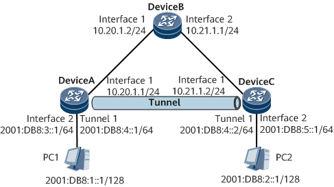
On the network shown in Figure 1, DeviceA, DeviceB, and DeviceC belong to the IPv4 backbone network and run OSPF.
It is required that an IPv6 direct link be established between DeviceA and DeviceC. To meet such a requirement, configure an IPv6 over IPv4 GRE tunnel between DeviceA and DeviceC and specify the tunnel interface as the outbound interface of an IPv6 static route. PC1 and PC2 can then communicate.
DeviceA and DeviceC are the default gateways of PC1 and PC2, respectively.

Configuration Roadmap
The configuration roadmap is as follows:
Configure an IPv4 dynamic routing protocol for communication between backbone network devices.
Create tunnel interfaces on DeviceA and DeviceC and specify the tunnel source and destination addresses. The tunnel source address is the IPv4 address of the interface that sends packets, and the tunnel destination address is the IPv4 address of the interface that receives packets.
Configure IPv6 addresses for the tunnel interfaces, so that the tunnel can advertise IPv6 routes.
Configure an IPv6 static route between DeviceA and PC1 and between DeviceC and PC2 and specify the local tunnel interface as the outbound interface of the corresponding static route, so that IPv6 traffic between PC1 and PC2 can be transmitted through the GRE tunnel.
Data Preparation
To complete the configuration, you need the following data:
Data required for running OSPF
Source and destination addresses of the GRE tunnel, and tunnel interface IP addresses
Procedure
- Configure IPv4 or IPv6 addresses for interfaces.
Configure an IP address for each interface as shown in Figure 1. For configuration details, see Configuration Files in this section.
- Configure an IGP on the VPN backbone network.
# Configure DeviceA.
[~DeviceA] ospf 1
[*DeviceA-ospf-1] area 0
[*DeviceA-ospf-1-area-0.0.0.0] network 10.20.1.0 0.0.0.255
[*DeviceA-ospf-1-area-0.0.0.0] quit
[*DeviceA-ospf-1] quit
[*DeviceA] commit
# Configure DeviceB.
[~DeviceB] ospf 1
[*DeviceB-ospf-1] area 0
[*DeviceB-ospf-1-area-0.0.0.0] network 10.20.1.0 0.0.0.255
[*DeviceB-ospf-1-area-0.0.0.0] network 10.21.1.0 0.0.0.255
[*DeviceB-ospf-1-area-0.0.0.0] quit
[*DeviceB-ospf-1] quit
[*DeviceB] commit
# Configure DeviceC.
[~DeviceC] ospf 1
[*DeviceC-ospf-1] area 0
[*DeviceC-ospf-1-area-0.0.0.0] network 10.21.1.0 0.0.0.255
[*DeviceC-ospf-1-area-0.0.0.0] quit
[*DeviceC-ospf-1] quit
[*DeviceC] commit
After the configuration is complete, run the display ip routing-table command on DeviceA and DeviceC. The command outputs show that they have learned the OSPF routes destined for each other.
# The following example uses the command output on DeviceA.
[~DeviceA] display ip routing-table
Route Flags: R - relay, D - download to fib, T - to vpn-instance, B - black hole route
------------------------------------------------------------------------------
Routing Table : _public_
         Destinations : 8       Routes : 8

Destination/Mask    Proto   Pre  Cost        Flags NextHop         Interface

      10.20.1.0/24  Direct  0    0             D  10.20.1.1       GigabitEthernet0/1/0
      10.20.1.1/32  Direct  0    0             D  127.0.0.1       GigabitEthernet0/1/0
    10.20.1.255/32  Direct  0    0             D  127.0.0.1       GigabitEthernet0/1/0
      10.21.1.0/24  OSPF    10   2             D  10.20.1.2       GigabitEthernet0/1/0
      127.0.0.0/8   Direct  0    0             D  127.0.0.1       InLoopBack0
      127.0.0.1/32  Direct  0    0             D  127.0.0.1       InLoopBack0
127.255.255.255/32  Direct  0    0             D  127.0.0.1       InLoopBack0
255.255.255.255/32  Direct  0    0             D  127.0.0.1       InLoopBack0
- Configure tunnel interfaces.
# Configure DeviceA.
[~DeviceA] interface GigabitEthernet 0/1/0
[~DeviceA-GigabitEthernet0/1/0] binding tunnel gre
[*DeviceA-GigabitEthernet0/1/0] commit
[~DeviceA-GigabitEthernet0/1/0] quit
[~DeviceA] interface tunnel 1
[*DeviceA-Tunnel1] tunnel-protocol gre
[*DeviceA-Tunnel1] ipv6 enable
[*DeviceA-Tunnel1] ipv6 address 2001:DB8:4::1 64
[*DeviceA-Tunnel1] source 10.20.1.1
[*DeviceA-Tunnel1] destination 10.21.1.2
[*DeviceA-Tunnel1] quit
[*DeviceA] commit
# Configure DeviceC.
[~DeviceC] interface GigabitEthernet 0/1/0
[~DeviceC-GigabitEthernet0/1/0] binding tunnel gre
[*DeviceC-GigabitEthernet0/1/0] commit
[~DeviceC-GigabitEthernet0/1/0] quit
[~DeviceC] interface tunnel 1
[*DeviceC-Tunnel1] tunnel-protocol gre
[*DeviceC-Tunnel1] ipv6 enable
[*DeviceC-Tunnel1] ipv6 address 2001:DB8:4::2 64
[*DeviceC-Tunnel1] source 10.21.1.2
[*DeviceC-Tunnel1] destination 10.20.1.1
[*DeviceC-Tunnel1] quit
[*DeviceC] commit
After the configuration is complete, the IPv6 status of tunnel interfaces becomes up and the tunnel interfaces can ping each other.
# The following example uses the command output on DeviceA.
[~DeviceA] ping ipv6 -a 2001:DB8:4::1 2001:DB8:4::2 PING 2001:DB8:4::2 : 56 data bytes, press CTRL_C to break Reply from 2001:DB8:4::2 bytes=56 Sequence=1 hop limit=64 time=409 ms Reply from 2001:DB8:4::2 bytes=56 Sequence=2 hop limit=64 time=14 ms Reply from 2001:DB8:4::2 bytes=56 Sequence=3 hop limit=64 time=12 ms Reply from 2001:DB8:4::2 bytes=56 Sequence=4 hop limit=64 time=16 ms Reply from 2001:DB8:4::2 bytes=56 Sequence=5 hop limit=64 time=14 ms --- 2001:DB8:4::2 ping statistics--- 5 packet(s) transmitted 5 packet(s) received 0.00% packet loss round-trip min/avg/max=12/93/409 ms - Configure static routes.
# Configure DeviceA.
[~DeviceA] ipv6 route-static 2001:DB8:2:: 64 tunnel1
[*DeviceA] commit
# Configure DeviceC.
[~DeviceC] ipv6 route-static 2001:DB8:1:: 64 tunnel1
[*DeviceC] commit
- Verifying the Configuration
After the configuration is complete, run the display ipv6 routing-table command on DeviceA and DeviceC. In the command output, you can find a static route with the next hop being the tunnel interface and destination being the user-side network segment of the peer.
# The following example uses the command output on DeviceA.
[~DeviceA] display ipv6 routing-table
Routing Table : _public_
         Destinations : 7        Routes : 7

Destination  : ::1                                     PrefixLength : 128
NextHop      : ::1                                     Preference   : 0
Cost         : 0                                       Protocol     : Direct
RelayNextHop : ::                                      TunnelID     : 0x0
Interface    : InLoopBack0                             Flags        : D

Destination  : ::FFFF:127.0.0.0                        PrefixLength : 104
NextHop      : ::FFFF:127.0.0.1                        Preference   : 0
Cost         : 0                                       Protocol     : Direct
RelayNextHop : ::                                      TunnelID     : 0x0
Interface    : InLoopBack0                             Flags        : D

Destination  : ::FFFF:127.0.0.1                        PrefixLength : 128
NextHop      : ::1                                     Preference   : 0
Cost         : 0                                       Protocol     : Direct
RelayNextHop : ::                                      TunnelID     : 0x0
Interface    : InLoopBack0                             Flags        : D

Destination  : 2001:DB8:2::                            PrefixLength : 64
NextHop      : 2001:DB8:4::1                           Preference   : 60
Cost         : 0                                       Protocol     : Static
RelayNextHop : ::                                      TunnelID     : 0x0
Interface    : Tunnel1                                 Flags        : D

Destination  : 2001:DB8:4::                            PrefixLength : 64
NextHop      : 2001:DB8:4::1                           Preference   : 0
Cost         : 0                                       Protocol     : Direct
RelayNextHop : ::                                      TunnelID     : 0x0
Interface    : Tunnel1                                 Flags        : D

Destination  : 2001:DB8:4::1                           PrefixLength : 128
NextHop      : ::1                                     Preference   : 0
Cost         : 0                                       Protocol     : Direct
RelayNextHop : ::                                      TunnelID     : 0x0
Interface    : Tunnel1                                 Flags        : D

Destination  : FE80::                                  PrefixLength : 10
NextHop      : ::                                      Preference   : 0
Cost         : 0                                       Protocol     : Direct
RelayNextHop : ::                                      TunnelID     : 0x0
Interface    : NULL0                                   Flags        : DB
Configuration Files
DeviceA configuration file
#
sysname DeviceA
#
interface GigabitEthernet 0/1/0
 undo shutdown
 ip address 10.20.1.1 255.255.255.0
 binding tunnel gre
#
interface GigabitEthernet 0/1/8
 undo shutdown
 ipv6 enable
 ipv6 address 2001:DB8:3::1/64
#
interface Tunnel1
 ipv6 enable
 ipv6 address 2001:DB8:4::1/64
 tunnel-protocol gre
 source 10.20.1.1
 destination 10.21.1.2
#
ospf 1
 area 0.0.0.0
  network 10.20.1.0 0.0.0.255
#
ipv6 route-static 2001:DB8:2:: 64 Tunnel1
#
return
DeviceB configuration file
#
sysname DeviceB
#
interface GigabitEthernet 0/1/0
 undo shutdown
 ip address 10.20.1.2 255.255.255.0
#
interface GigabitEthernet 0/1/8
 undo shutdown
 ip address 10.21.1.1 255.255.255.0
#
ospf 1
 area 0.0.0.0
  network 10.20.1.0 0.0.0.255
  network 10.21.1.0 0.0.0.255
#
return
DeviceC configuration file
#
sysname DeviceC
#
interface GigabitEthernet 0/1/0
 undo shutdown
 ip address 10.21.1.2 255.255.255.0
 binding tunnel gre
#
interface GigabitEthernet 0/1/8
 undo shutdown
 ipv6 enable
 ipv6 address 2001:DB8:5::1/64
#
interface Tunnel1
 ipv6 enable
 ipv6 address 2001:DB8:4::2/64
 tunnel-protocol gre
 source 10.21.1.2
 destination 10.20.1.1
#
ospf 1
 area 0.0.0.0
 network 10.21.1.0 0.0.0.255
#
ipv6 route-static 2001:DB8:1:: 64 Tunnel1
#
return