Example for Configuring a Dynamic Routing Protocol for GRE
This section provides an example for configuring a dynamic route for GRE. In this networking scheme, traffic between users is transmitted through a GRE tunnel; a dynamic route is configured between the device and its connected user.
Networking Requirements
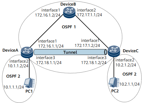
In Figure 1, Device A, Device B, and Device C belong to the VPN backbone network, and OSPF runs between them.
GRE is enabled between Device A and Device C for the interworking between PC1 and PC2.
OSPF is enabled on the tunnel interface. OSPF process 1 is used for the VPN backbone network, and OSPF process 2 is used for user access.
PC1 takes Device A as its default gateway, and PC2 takes Device C as its default gateway.

Configuration Roadmap
The configuration roadmap is as follows:
Configure IGP on each router in the backbone network to realize the interworking between these devices. Here OSPF process 1 is used.
Create the GRE tunnel between routers that are connected to PCs. Then routers can communicate through the GRE tunnel.
Configure the dynamic routing protocol on the network segments through which PCs access the backbone network. Here OSPF process 2 is used.
Data Preparation
To complete the configuration, you need the following data:
Source address and destination address of the GRE tunnel
IP addresses of the interfaces on both ends of the GRE tunnel
Procedure
- Configure IP addresses for interfaces.
For configuration details, see Configuration Files in this section.
- Configure IGP for the VPN backbone network.
The specific configuration procedures are the same as those in Example for Configuring a Static Route for GRE and are not mentioned here.
- Configuring the tunnel interfaces
The specific configuration procedures are the same as those in Example for Configuring a Static Route for GRE and are not mentioned here.
- Configure OSPF on the tunnel interfaces.
# Configure Device A.
[~DeviceA] ospf 2
[*DeviceA-ospf-2] area 0
[*DeviceA-ospf-2-area-0.0.0.0] network 172.18.1.0 0.0.0.255
[*DeviceA-ospf-2-area-0.0.0.0] network 10.1.1.0 0.0.0.255
[*DeviceA-ospf-2-area-0.0.0.0] quit
[*DeviceA-ospf-2] quit
[*DeviceA] commit
# Configure Device C.
[~DeviceC] ospf 2
[*DeviceC-ospf-2] area 0
[*DeviceC-ospf-2-area-0.0.0.0] network 172.18.1.0 0.0.0.255
[*DeviceC-ospf-2-area-0.0.0.0] network 10.2.1.0 0.0.0.255
[*DeviceC-ospf-2-area-0.0.0.0] quit
[*DeviceC-ospf-2] quit
[*DeviceC] commit
- Verify the configuration.
After the configuration, run the display ip routing-table command on Device A and Device C. The command output shows the OSPF route to the network segment of the remote user end through the tunnel interface. Moreover, the next hop to the destination physical address (172.17.1.0/24) of the tunnel is not the tunnel interface.
Take Device A as an example:
[~DeviceA] display ip routing-table
Route Flags: R - relay, D - download to fib, T - to vpn-instance, B - black hole route
------------------------------------------------------------------------------
Routing Table : _public_
         Destinations : 15       Routes : 15

Destination/Mask    Proto   Pre  Cost        Flags NextHop         Interface

        1.1.1.1/32  Direct  0    0             D  127.0.0.1       InLoopBack0
        2.2.2.2/24  OSPF    10   2             D  172.16.1.2      Vlanif10
       10.1.1.0/24  Direct  0    0             D  10.1.1.2        Vlanif20
       10.1.1.2/32  Direct  0    0             D  127.0.0.1       Vlanif20
     10.1.1.255/32  Direct  0    0             D  127.0.0.1       Vlanif20
       10.2.1.0/24  OSPF    10  2              D  172.18.1.2      Tunnel1
     172.16.1.0/24  Direct  0    0             D  172.16.1.1      Vlanif10
     172.16.1.1/32  Direct  0    0             D  127.0.0.1       Vlanif10
   172.16.1.255/32  Direct  0    0             D  127.0.0.1       Vlanif10
     172.17.1.0/24  OSPF    10  2              D  172.16.1.2      Vlanif10
     172.18.1.0/24  Direct  0    0             D  172.18.1.1      Tunnel1
     172.18.1.1/32  Direct  0    0             D  127.0.0.1       Tunnel1
   172.18.1.255/32  Direct  0    0             D  127.0.0.1       Tunnel1
      127.0.0.0/8   Direct  0    0             D  127.0.0.1       InLoopBack0
      127.0.0.1/32  Direct  0    0             D  127.0.0.1       InLoopBack0
127.255.255.255/32  Direct  0    0             D  127.0.0.1       InLoopBack0
255.255.255.255/32  Direct  0    0             D  127.0.0.1       InLoopBack0
Configuration Files
Configuration file of Device A
#
sysname DeviceA
#
vlan batch 10 20
#
interface Vlanif10
 ip address 172.16.1.1 255.255.255.0
#
interface Vlanif20
 ip address 10.1.1.2 255.255.255.0
#
interface GigabitEthernet0/1/0
 portswitch
 undo shutdown
 port default vlan 10
#
interface GigabitEthernet0/1/8
 portswitch
 undo shutdown
 port default vlan 20
#
interface LoopBack1
 ip address 1.1.1.1 255.255.255.255
 binding tunnel gre
#
interface Tunnel1
 ip address 172.18.1.1 255.255.255.0
 tunnel-protocol gre
 source 1.1.1.1
 destination 2.2.2.2
#
ospf 1
 area 0.0.0.0
  network 1.1.1.1 0.0.0.0
  network 172.16.1.0 0.0.0.255
#
ospf 2
 area 0.0.0.0
  network 10.1.1.0 0.0.0.255
  network 172.18.1.0 0.0.0.255
#
return
Configuration file of Device B
#
sysname DeviceB
#
vlan batch 10 20
#
interface Vlanif10
 ip address 172.16.1.2 255.255.255.0
#
interface Vlanif20
 ip address 172.17.1.1 255.255.255.0
#
interface GigabitEthernet0/1/0
 portswitch
 undo shutdown
 port default vlan 10
#
interface GigabitEthernet0/1/8
 portswitch
 undo shutdown
 port default vlan 20
#
ospf 1
 area 0.0.0.0
  network 172.16.1.0 0.0.0.255
  network 172.17.1.0 0.0.0.255
#
return
Configuration file of Device C
#
sysname DeviceC
#
vlan batch 10 20
#
interface Vlanif10
 ip address 10.2.1.2 255.255.255.0
#
interface Vlanif20
 ip address 172.17.1.2 255.255.255.0
#
interface GigabitEthernet0/1/0
 portswitch
 undo shutdown
 port default vlan 20
#
interface GigabitEthernet0/1/8
 portswitch
 undo shutdown
 port default vlan 10
#
interface LoopBack1
 ip address 2.2.2.2 255.255.255.255
 binding tunnel gre
#
interface Tunnel1
 ip address 172.18.1.2 255.255.255.0
 tunnel-protocol gre
 source 2.2.2.2
 destination 1.1.1.1
#
ospf 1
 area 0.0.0.0
  network 2.2.2.2 0.0.0.0
  network 172.17.1.0 0.0.0.255
#
ospf 2
 area 0.0.0.0
  network 10.2.1.0 0.0.0.255
  network 172.18.1.0 0.0.0.255
#
return