Example for Configuring Public Network IPv4 FRR
With public network IPv4 FRR, traffic can be rapidly switched to a backup link if the primary link fails.
Networking Requirements
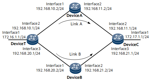
On the network shown in Figure 1, it is required that the backup outbound interface and backup next hop be configured on Device T to ensure that Link B functions as a backup of Link A. If Link A fails, traffic is rapidly switched to the backup link (Link B).

Precautions
Before configuring public network IPv4 FRR, there must be at least two routes of different routing protocols but destined for the same IP address.
Configuration Roadmap
The configuration roadmap is as follows:
Configure basic OSPF functions on Device T, Device A, and Device C (OSPFv3 process ID is 1).
Configure basic IS-IS functions on Device T, Device B, and Device C.
Enable public network IPv4 FRR on Device T, and check the backup outbound interface and backup next hop.
Disable IPv4 FRR, and check the backup outbound interface and backup next hop.
Data Preparation
To complete the configuration, you need the following data:
OSPF process IDs of Device T, Device A, and Device C
IS-IS area addresses of Device T, Device B, and Device C
Procedure
- Configure an IP address for each interface. For configuration details, see Configuration Files in this section.
- Configure OSPF on Device T, Device A, and Device C. For configuration details, see Configuration Files in this section.
- Configure IS-IS on Device T, Device B, and Device C. For configuration details, see Configuration Files in this section.
- Check routing information.
# Check the routes to 172.17.1.0 on Device T.
<DeviceT> display ip routing-table 172.17.1.0 verbose
Route Flags: R - relay, D - download to fib, T - to vpn-instance, B - black hole route ------------------------------------------------------------------------------
Routing Table : _public_
         Destinations : 1        Routes : 2

Destination: 172.17.1.0/24
     Protocol: OSPF            Process ID: 1
   Preference: 10                    Cost: 3
      NextHop: 192.168.10.2     Neighbour: 0.0.0.0
        State: Active Adv             Age: 00h00m07s
          Tag: 0                 Priority: low
        Label: NULL               QoSInfo: 0xa98ac7
   IndirectID: 0x40000041
 RelayNextHop: 0.0.0.0          Interface: GigabitEthernet0/1/8
     TunnelID: 0x0                  Flags: D

Destination: 172.17.1.0/24
     Protocol: ISIS            Process ID: 1
   Preference: 15                    Cost: 30
      NextHop: 192.168.20.2     Neighbour: 0.0.0.0
        State: Inactive Adv           Age: 00h01m26s
          Tag: 0                 Priority: high
        Label: NULL               QoSInfo: 0xa98ac7
   IndirectID: 0x80000081
 RelayNextHop: 0.0.0.0          Interface: GigabitEthernet0/1/16
     TunnelID: 0x0                  Flags: 0
In the routing table, you can view that there are two routes to 172.17.1.0/24. The route with 192.168.10.2 as the next hop is optimal because the OSPF route priority is higher than the IS-IS route priority.
- Enable public network IPv4 FRR.
# Enable IPv4 FRR on Device T.
[~DeviceT] ip frr
[*DeviceT] commit
# Check the backup outbound interface and backup next hop on Device T.
<DeviceT> display ip routing-table 172.17.1.0 verbose
Route Flags: R - relay, D - download to fib, T - to vpn-instance, B - black hole route ------------------------------------------------------------------------------
Routing Table : _public_
         Destinations : 1        Routes : 2

Destination: 172.17.1.0/24
     Protocol: OSPF            Process ID: 1
   Preference: 10                    Cost: 3
      NextHop: 192.168.10.2     Neighbour: 0.0.0.0
        State: Active Adv             Age: 00h01m36s
          Tag: 0                 Priority: low
        Label: NULL               QoSInfo: 0xa98ac7
   IndirectID: 0x40000041
 RelayNextHop: 0.0.0.0          Interface: GigabitEthernet0/1/8
     TunnelID: 0x0                  Flags: D
    BkNextHop: 192.168.20.2   BkInterface: GigabitEthernet0/1/16
      BkLabel: NULL           SecTunnelID: 0x0
 BkPETunnelID: 0x0        BkPESecTunnelID: 0x0
 BkIndirectID: 0x80000081

Destination: 172.17.1.0/24
     Protocol: ISIS            Process ID: 1
   Preference: 15                    Cost: 30
      NextHop: 192.168.20.2     Neighbour: 0.0.0.0
        State: Inactive Adv           Age: 00h02m55s
          Tag: 0                 Priority: high
        Label: NULL               QoSInfo: 0xa98ac7
   IndirectID: 0x80000081
 RelayNextHop: 0.0.0.0          Interface: GigabitEthernet0/1/16
     TunnelID: 0x0                  Flags: 0
The routing table shows that the route to 172.17.1.0/24 has the backup outbound interface and backup next hop and that the IS-IS route is the backup route.
- Verify the configuration.
# Simulate a link fault on Device T.
[~DeviceT] interface gigabitethernet 0/1/8
[~DeviceT-GigabitEthernet0/1/8] shutdown
[*DeviceT-GigabitEthernet0/1/8] commit
[~DeviceT-GigabitEthernet0/1/8] quit
# Check the routes to 172.17.1.0/24 on Device T.
<DeviceT> display ip routing-table 172.17.1.0 verbose
Route Flags: R - relay, D - download to fib, T - to vpn-instance, B - black hole route ------------------------------------------------------------------------------
Routing Table : _public_
         Destinations : 1        Routes : 1

Destination: 172.17.1.0/24
     Protocol: ISIS            Process ID: 1
   Preference: 15                    Cost: 30
      NextHop: 192.168.20.2     Neighbour: 0.0.0.0
        State: Active Adv             Age: 00h57m30s
          Tag: 0                 Priority: high
        Label: NULL               QoSInfo: 0xa98ac7
   IndirectID: 0x80000081
 RelayNextHop: 0.0.0.0          Interface: GigabitEthernet0/1/16
     TunnelID: 0x0                  Flags: D
The preceding command output shows that traffic has been switched to the backup link (Link B).
Configuration Files
Device T configuration file
#
sysname DeviceT
#
ip frr
#
isis 1
 network-entity 10.0000.0000.0001.00
#
interface GigabitEthernet0/1/0
 undo shutdown
 ip address 172.16.1.1 255.255.255.0
#
interface GigabitEthernet0/1/8
 undo shutdown
 ip address 192.168.10.1 255.255.255.0
#
interface GigabitEthernet0/1/16
 undo shutdown
 ip address 192.168.20.1 255.255.255.0
 isis enable 1
#
ospf 1
 area 0.0.0.0
  network 192.168.10.0 0.0.0.255
 area 0.0.0.1
  network 172.16.1.0 0.0.0.255
#
return
Device A configuration file
#
sysname DeviceA
#
interface GigabitEthernet0/1/0
 undo shutdown
 ip address 192.168.10.2 255.255.255.0
#
interface GigabitEthernet0/1/8
 undo shutdown
 ip address 192.168.11.2 255.255.255.0
#
ospf 1
 area 0.0.0.0
  network 192.168.10.0 0.0.0.255
  network 192.168.11.0 0.0.0.255
#
return
Device B configuration file
#
sysname DeviceB
#
isis 1
 network-entity 10.0000.0000.0002.00
#
interface GigabitEthernet0/1/0
 undo shutdown
 ip address 192.168.20.2 255.255.255.0
 isis enable 1
#
interface GigabitEthernet0/1/8
 undo shutdown
 ip address 192.168.21.2 255.255.255.0
 isis enable 1
#
return
Device C configuration file
#
sysname DeviceC
#
isis 1
 network-entity 10.0000.0000.0003.00
#
interface GigabitEthernet0/1/0
 undo shutdown
 ip address 172.17.1.1 255.255.255.0
 isis enable 1
#
interface GigabitEthernet0/1/8
 undo shutdown
 ip address 192.168.11.1 255.255.255.0
#
interface GigabitEthernet0/1/16
 undo shutdown
 ip address 192.168.21.1 255.255.255.0
 isis enable 1
#
ospf 1
 area 0.0.0.0
  network 192.168.11.0 0.0.0.255
  network 192.168.21.0 0.0.0.255
 area 0.0.0.2
  network 172.17.1.0 0.0.0.255
#
return