Example for Importing IPv4 ARP Vlink Direct Routes to BGP
By importing IPv4 ARP Vlink direct routes to BGP, you can enable the remote device to obtain information about detailed routes in the VLAN, allowing precise control of data traffic.
Networking Requirements
As networks develop, the VLAN technology is widely used. If a user outside a VLAN needs to communicate with users within the VLAN, advertising routes destined for the network segment of the VLAN can achieve this purpose. When users outside the VLAN need to know the IPv4 ARP Vlink direct routes of the VLAN, and apply different traffic policies to routes of the VLAN users, advertising the routes destined for the network segment of the VLAN cannot meet this requirement.
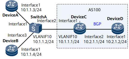
In this case, you can enable the function of IPv4 ARP Vlink direct route advertisement. As shown in Figure 1, Device C is connected to two VLAN sites through VLANIF interfaces. Device D communicates with Device B, but not with Device A. To meet the communication requirement, you can enable the function of IPv4 ARP Vlink direct route advertisement on Device C, and use a route-policy to filter out the routes to the network segment of the VLAN and the route to Device A.

Configuration Roadmap
The configuration roadmap is as follows:
Create VLANIF interfaces on Switch A and Device C and assign IP addresses to the VLANIF interfaces, and ensure that Device A, Device B, Switch A, and Device C can communicate with each other.
- Enable BGP on Device C and Device D, ensuring that Device C and Device D are able to advertise IP routes to each other.
Enable the function of IPv4 ARP Vlink direct route advertisement on Device C.
Configure a route-policy on Device C, allowing routes only from Device B to pass through.
Enable BGP on Device C to import direct routes, and use the route-policy to import routes only from Device B.
Associate BGP with the route-policy on Device C to filter out the network segment route of the VLAN so that Device D cannot learn the network segment route and can communicate with VLAN users based only on IPv4 ARP Vlink direct routes.
Data Preparation
To complete the configuration, you need the following data:
ID of the VLAN in which Switch A and Device C reside (the VLAN ID is 10 in this example)
Router IDs and AS numbers of Devices C and D (router ID of Device C is 3.3.3.3 and router ID of Device D is 4.4.4.4, and Devices C and D are in AS 100 in this example)
Route-policy used to filter direct routes (the route-policy is policy1 in this example)
Route-policy used to advertise BGP routes on Device C (the route-policy is policy2 in this example)
Procedure
- Configure an IP address for each interface.
# Configure Device A.
<HUAWEI> system-view
[~HUAWEI] sysname DeviceA
[*HUAWEI] commit
[~DeviceA] interface GigabitEthernet 0/1/0
[*DeviceA-GigabitEthernet0/1/0] undo shutdown
[*DeviceA-GigabitEthernet0/1/0] ip address 10.1.1.3 24
[*DeviceA-GigabitEthernet0/1/0] commit
[~DeviceA-GigabitEthernet0/1/0] quit
# Configure Device B.
<HUAWEI> system-view
[~HUAWEI] sysname DeviceB
[*HUAWEI] commit
[~DeviceB] interface GigabitEthernet 0/1/0
[*DeviceB-GigabitEthernet0/1/0] undo shutdown
[*DeviceB-GigabitEthernet0/1/0] ip address 10.1.1.4 24
[*DeviceB-GigabitEthernet0/1/0] commit
[~DeviceB-GigabitEthernet0/1/0] quit
# Configure Device C.
<HUAWEI> system-view
[~HUAWEI] sysname DeviceC
[*HUAWEI] commit
[~DeviceC] interface GigabitEthernet 0/1/8
[*DeviceC-GigabitEthernet0/1/8] undo shutdown
[*DeviceC-GigabitEthernet0/1/8] ip address 10.2.1.1 24
[*DeviceC-GigabitEthernet0/1/8] commit
[~DeviceC-GigabitEthernet0/1/8] quit
# Configure Device D.
<HUAWEI> system-view
[~HUAWEI] sysname DeviceD
[*HUAWEI] commit
[~DeviceD] interface GigabitEthernet 0/1/0
[*DeviceD-GigabitEthernet0/1/0] undo shutdown
[*DeviceD-GigabitEthernet0/1/0] ip address 10.2.1.2 24
[*DeviceD-GigabitEthernet0/1/0] commit
[~DeviceD-GigabitEthernet0/1/0] quit
- Configure basic VLAN functions. Create VLANIF 10 on Switch A and Device C and assign IP addresses to the VLANIF interfaces.
# Configure Switch A.
<HUAWEI> system-view
[~HUAWEI] sysname SwitchA
[*HUAWEI] commit
[~SwitchA] vlan 10
[*SwitchA-vlan10] quit
[*SwitchA] interface GigabitEthernet 0/1/0
[*SwitchA-GigabitEthernet0/1/0] portswitch
[*SwitchA-GigabitEthernet0/1/0] undo shutdown
[*SwitchA-GigabitEthernet0/1/0] port link-type access
[*SwitchA-GigabitEthernet0/1/0] port default vlan 10
[*SwitchA-GigabitEthernet0/1/0] quit
[*SwitchA] interface GigabitEthernet 0/1/8
[*SwitchA-GigabitEthernet0/1/8] portswitch
[*SwitchA-GigabitEthernet0/1/8] undo shutdown
[*SwitchA-GigabitEthernet0/1/8] port link-type access
[*SwitchA-GigabitEthernet0/1/8] port default vlan 10
[*SwitchA-GigabitEthernet0/1/8] quit
[*SwitchA] interface GigabitEthernet 0/1/16
[*SwitchA-GigabitEthernet0/1/16] portswitch
[*SwitchA-GigabitEthernet0/1/16] undo shutdown
[*SwitchA-GigabitEthernet0/1/16] port link-type access
[*SwitchA-GigabitEthernet0/1/16] port default vlan 10
[*SwitchA-GigabitEthernet0/1/16] quit
[*SwitchA] interface Vlanif 10
[*SwitchA-Vlanif10] ip address 10.1.1.2 24
[*SwitchA-Vlanif10] commit
[~SwitchA-Vlanif10] quit
# Configure Device C.
[~DeviceC] vlan 10
[*DeviceC-vlan10] quit
[*DeviceC] interface GigabitEthernet 0/1/0
[*DeviceC-GigabitEthernet0/1/0] portswitch
[*DeviceC-GigabitEthernet0/1/0] undo shutdown
[*DeviceC-GigabitEthernet0/1/0] port link-type access
[*DeviceC-GigabitEthernet0/1/0] port default vlan 10
[*DeviceC-GigabitEthernet0/1/0] quit
[*DeviceC] interface Vlanif 10
[*DeviceC-Vlanif10] ip address 10.1.1.1 24
[*DeviceC-Vlanif10] commit
[~DeviceC-Vlanif10] quit
- Configure BGP between Device C and Device D.
# Configure Device C.
[~DeviceC] bgp 100
[*DeviceC-bgp] router-id 3.3.3.3
[*DeviceC-bgp] peer 10.2.1.2 as-number 100
[*DeviceC-bgp] commit
[~DeviceC-bgp] quit
# Configure Device D.
[~DeviceD] bgp 100
[*DeviceD-bgp] router-id 4.4.4.4
[*DeviceD-bgp] peer 10.2.1.1 as-number 100
[*DeviceD-bgp] commit
[~DeviceD-bgp] quit
- Configure BGP on Device C and import direct routes to BGP. Then view the routing tables of Devices C and D.
# Configure Device C.
[~DeviceC] bgp 100
[~DeviceC-bgp] import-route direct
[*DeviceC-bgp] commit
[~DeviceC-bgp] quit
# Display the BGP routing table of Device C.
[~DeviceC] display bgp routing-table
 BGP Local router ID is 3.3.3.3
 Status codes: * - valid, > - best, d - damped, x - best external, a - add path,
               h - history,  i - internal, s - suppressed, S - Stale
               Origin : i - IGP, e - EGP, ? - incomplete
 RPKI validation codes: V - valid, I - invalid, N - not-found

 Total Number of Routes: 9
      Network            NextHop        MED        LocPrf    PrefVal Path/Ogn

 *>   10.1.1.0/24        0.0.0.0         0                     0      ?
 *>   10.1.1.1/32        0.0.0.0         0                     0      ?
 *>   10.1.1.2/32        0.0.0.0         0                     0      ?
 *>   10.2.1.0/24        0.0.0.0         0                     0      ?
 *>   10.2.1.1/32        0.0.0.0         0                     0      ?
 *>   127.0.0.0          0.0.0.0         0                     0      ?
 *>   127.0.0.1/32       0.0.0.0         0                     0      ?
# Display the BGP routing table of Device D.
[~DeviceD] display bgp routing-table
 BGP Local router ID is 4.4.4.4
 Status codes: * - valid, > - best, d - damped, x - best external, a - add path,
               h - history,  i - internal, s - suppressed, S - Stale
               Origin : i - IGP, e - EGP, ? - incomplete
 RPKI validation codes: V - valid, I - invalid, N - not-found

 Total Number of Routes: 2
      Network            NextHop        MED        LocPrf    PrefVal Path/Ogn

 *>i  10.1.1.0/24        10.2.1.1        0          100        0      ?
   i  10.2.1.0/24        10.2.1.1        0          100        0      ?
You can see that Device D has not learned the two IPv4 ARP Vlink direct routes 10.1.1.3/32 and 10.1.1.4/32.
- Enable the function of IPv4 ARP Vlink direct route advertisement on Device C and configure the route-policy policy1 to filter out the routes to the network segment of the VLAN and the IPv4 ARP Vlink direct route from Device A, 10.1.1.3/32.
# Configure Device C.
[~DeviceC] ip ip-prefix prefix1 permit 10.1.1.4 32
[*DeviceC] route-policy policy1 permit node 10
[*DeviceC-route-policy] if-match ip-prefix prefix1
[*DeviceC-route-policy] quit
[*DeviceC] arp vlink-direct-route advertise route-policy policy1
[*DeviceC] commit
# Display the BGP routing table of Device C.
[~DeviceC] display bgp routing-table
 BGP Local router ID is 3.3.3.3
 Status codes: * - valid, > - best, d - damped, x - best external, a - add path,
               h - history,  i - internal, s - suppressed, S - Stale
               Origin : i - IGP, e - EGP, ? - incomplete
 RPKI validation codes: V - valid, I - invalid, N - not-found

 Total Number of Routes: 9
      Network            NextHop        MED        LocPrf    PrefVal Path/Ogn

 *>   10.1.1.0/24        0.0.0.0         0                     0      ?
 *>   10.1.1.1/32        0.0.0.0         0                     0      ?
 *>   10.1.1.2/32        0.0.0.0         0                     0      ?
 *>   10.1.1.3/32        0.0.0.0         0                     0      ?
 *>   10.1.1.4/32        0.0.0.0         0                     0      ?
 *>   10.2.1.0/24        0.0.0.0         0                     0      ?
 *>   10.2.1.1/32        0.0.0.0         0                     0      ?
 *>   127.0.0.0          0.0.0.0         0                     0      ?
 *>   127.0.0.1/32       0.0.0.0         0                     0      ?
# Display the BGP routing table of Device D.
[~DeviceD] display bgp routing-table
 BGP Local router ID is 4.4.4.4
 Status codes: * - valid, > - best, d - damped, x - best external, a - add path,
               h - history,  i - internal, s - suppressed, S - Stale
               Origin : i - IGP, e - EGP, ? - incomplete
 RPKI validation codes: V - valid, I - invalid, N - not-found

 Total Number of Routes: 3
      Network            NextHop        MED        LocPrf    PrefVal Path/Ogn

 *>i  10.1.1.0/24        10.2.1.1        0          100        0      ?
 *>i  10.1.1.4/32        10.2.1.1        0          100        0      ?
   i  10.2.1.0/24        10.2.1.1        0          100        0      ?
You can see that Device D has learned the IPv4 ARP Vlink direct route 10.1.1.4/32, whereas the route 10.1.1.3/32 has been filtered out.
- Use the route-policy policy2 to filter out the network segment route 10.1.1.0/24 on Device C when BGP routes are advertised.
# Configure Device C.
[~DeviceC] ip ip-prefix prefix2 index 10 deny 10.1.1.0 24
[*DeviceC] ip ip-prefix prefix2 index 20 permit 0.0.0.0 0 less-equal 32
[*DeviceC] route-policy policy2 permit node 10
[*DeviceC-route-policy] if-match ip-prefix prefix2
[*DeviceC-route-policy] quit
[*DeviceC] bgp 100
[*DeviceC-bgp] peer 10.2.1.2 route-policy policy2 export
[*DeviceC-bgp] commit
[~DeviceC-bgp] quit
[~DeviceC] quit
<DeviceC> refresh bgp all export
# Display the BGP routing table of Device D.
[~DeviceD] display bgp routing-table
 BGP Local router ID is 4.4.4.4
 Status codes: * - valid, > - best, d - damped, x - best external, a - add path,
               h - history,  i - internal, s - suppressed, S - Stale
               Origin : i - IGP, e - EGP, ? - incomplete
 RPKI validation codes: V - valid, I - invalid, N - not-found

 Total Number of Routes: 2
      Network            NextHop        MED        LocPrf    PrefVal Path/Ogn

 *>i  10.1.1.4/32        10.2.1.1        0          100        0      ?
   i  10.2.1.0/24        10.2.1.1        0          100        0      ?
You can find that the route 10.1.1.0/24 does not exist in the BGP routing table of Device D. As a result, Device D can communicate with Device B, but cannot communicate with Device A.
Configuration Files
Configuration file of Switch A
#
sysname switchA
#
vlan batch 10
#
interface Vlanif10
 ip address 10.1.1.2 255.255.255.0
#
interface GigabitEthernet0/1/0
 portswitch
 undo shutdown
 port link-type access
 port default vlan 10
#
interface GigabitEthernet0/1/8
 portswitch
 undo shutdown
 port link-type access
 port default vlan 10
#
interface GigabitEthernet0/1/16
 portswitch
 undo shutdown
 port link-type access
 port default vlan 10
#
return
Configuration file of Device A
#
sysname DeviceA
#
interface GigabitEthernet0/1/0
 undo shutdown
 ip address 10.1.1.3 255.255.255.0
#
return
Configuration file of Device B
#
sysname DeviceB
#
interface GigabitEthernet0/1/0
 undo shutdown
 ip address 10.1.1.4 255.255.255.0
#
return
Configuration file of Device C
#
sysname DeviceC
#
ip ip-prefix prefix1 index 10 permit 10.1.1.4 32
ip ip-prefix prefix2 index 10 deny 10.1.1.0 24
ip ip-prefix prefix2 index 20 permit 0.0.0.0 0 less-equal 32
#
route-policy policy1 permit node 10
 if-match ip-prefix prefix1
#
route-policy policy2 permit node 10
 if-match ip-prefix prefix2
#
arp vlink-direct-route advertise route-policy policy1
#
vlan batch 10
#
interface Vlanif10
 ip address 10.1.1.1 255.255.255.0
#
interface GigabitEthernet0/1/0
 portswitch
 undo shutdown
 port link-type access
 port default vlan 10
#
interface GigabitEthernet0/1/8
 undo shutdown
 ip address 10.2.1.1 255.255.255.0
#
bgp 100
 router-id 3.3.3.3
 peer 10.2.1.2 as-number 100
 #
 ipv4-family unicast
  undo synchronization
  import-route direct
  peer 10.2.1.2 enable
  peer 10.2.1.2 route-policy policy2 export
#
return
Configuration file of Device D
#
sysname DeviceD
#
interface GigabitEthernet0/1/0
 undo shutdown
 ip address 10.2.1.2 255.255.255.0
#
#
bgp 100
 router-id 4.4.4.4
 peer 10.2.1.1 as-number 100
 #
 ipv4-family unicast
  undo synchronization
  peer 10.2.1.1 enable
#
return