Configuring a DCP
A Data Collecting Point (DCP) manages and controls Target Logical Ports (TLPs), collects statistics generated by TLPs, and reports the statistics to a Measurement Control Point (MCP).
Context
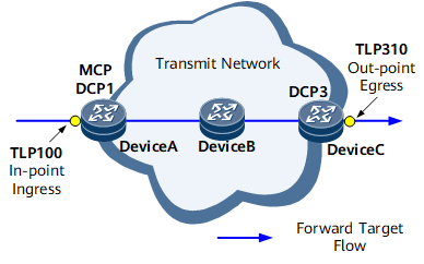
As shown in Figure 1, Device A and Device C function as DCPs to manage and control TLP100 and TLP310, respectively. Device A and Device C collect statistics generated by TLP100 and TLP310 and report the statistics to the MCP.
Perform the following steps on Device A and Device C:
Procedure
- Run system-view
The system view is displayed.
- Run nqa ipfpm dcp
DCP is enabled globally, and the IPFPM-DCP view is displayed.
- Run dcp id id-value
A DCP ID is configured.
Using the Router ID of a device that is configured as a DCP as its DCP ID is recommended.
The DCP ID configured on a DCP must be the same as that specified in the dcp dcp-id command run in the IP FPM instance view of the MCP associated with this DCP. Otherwise, the MCP cannot process the statistics reported by the DCP.
- (Optional) Run authentication-mode hmac-sha256 key-id key-id [ cipher ] [ password | password ]
The authentication mode and password are configured on the DCP.
The authentication mode and password configured on a DCP must be the same as those configured in the authentication-mode hmac-sha256 key-id key-id [ cipher ] [ password | password ] command run on the MCP associated with this DCP. Otherwise, the MCP cannot process the statistics reported by the DCP.
- (Optional) Run color-flag loss-measure { tos-bit tos-bit | flags-bit0 } delay-measure { tos-bit tos-bit | flags-bit0 }
IP FPM measurement flags are configured.
The loss and delay measurement flags cannot use the same bit, and the bits used for loss and delay measurement must not have been used in other measurement tasks.
- Run mcp mcp-id [ port port-number ] [ vpn-instance vpn-instance-name | net-manager-vpn ]
An MCP ID is specified for the DCP, and the UDP port number is configured for the DCP to communicate with the MCP.
The UDP port number configured on the DCP must be the same as that configured in the protocol udp port port-number command run on the MCP associated with this DCP. Otherwise, the DCP cannot report the statistics to the MCP.
The VPN instance has been created on the DCP before you configure vpn-instance vpn-instance-name or net-manager-vpn to allow the DCP to report the statistics to the MCP through the specified VPN or management VPN.
- (Optional) Run period source ntp
The DCP is configured to select NTP as the clock source when calculating an IP FPM statistical period ID.
In P2MP (MP being two points) delay measurement scenarios, if the ingress of the service traffic uses NTP as the clock source, but the egresses use a different clock source, for example, NTP or 1588v2, you must configure the egresses to select NTP as the clock source when calculating an IP FPM statistical period ID to ensure consistent clock sources on the ingress and egresses.
- Run instance instance-id
An IP FPM instance is created, and the instance view is displayed.
instance-id must be unique on an MCP and all its associated DCPs. The MCP and all its associated DCPs must have the same IP FPM instance configured. Otherwise, statistics collection does not take effect.
- (Optional) Run description text
The description is configured for the IP FPM instance.
The description of an IP FPM instance can contain the functions of the instance, facilitating applications.
- (Optional) Run interval interval
The statistical period is configured for the IP FPM instance.
- Perform either of the following operations to configure the target flow characteristics in the IP FPM instance.Configure the forward or backward target flow characteristics.
When protocol is specified as TCP or UDP, run:
flow { forward | backward } { protocol { tcp | udp } { source-port src-port-number1 [ to src-port-number2 ] | destination-port dest-port-number1 [ to dest-port-number2 ] } * | dscp dscp-value | source src-ip-address [ src-mask-length ] | destination dest-ip-address [ dest-mask-length ] } *
When protocol is specified as any protocol other than TCP or UDP, run:
Configure the bidirectional target flow characteristics.When protocol is specified as TCP or UDP, run:
flow bidirectional { protocol { tcp | udp } { source-port src-port-number1 [ to src-port-number2 ] | destination-port dest-port-number1 [ to dest-port-number2 ] } * | dscp dscp-value | source src-ip-address [ src-mask-length ] | destination dest-ip-address [ dest-mask-length ] } *
When protocol is specified as any protocol other than TCP or UDP, run:

If the target flow in an IP FPM instance is unidirectional, only forward can be specified.
- If the target flow in an IP FPM instance is bidirectional, two situations are available:
- If the bidirectional target flow is asymmetrical, you must configure forward and backward in two command instances to configure the forward and backward flow characteristics.
- If the bidirectional target flow is symmetrical, you can specify bidirectional to configure the bidirectional target flow characteristics. By default, the characteristics specified are used for the forward flow, and the reverse of those are used for the backward flow. Specifically, the source and destination IP addresses and port numbers specified for the forward flow are used respectively as the destination and source IP addresses and port numbers for the backward flow. If the target flow is symmetrical bidirectional, set src-ip-address to specify a source IP address and dest-ip-address to specify a destination IP address for the target flow.
- Run tlp tlp-id { in-point | out-point } { ingress | egress } [ vpn-label vpn-label [ lsp-label lsp-label ] ] [ backward-vpn-label backward-vpn-label [ backward-lsp-label backward-lsp-label ] ]
A TLP is configured and its role is specified.
A TLP compiles statistics and outputs data in the IP FPM model. A TLP can be specified as an in-point or an out-point. The system sets the measurement flags of target flows on an in-point, and clears the measurement flags of target flows on an out-point. TLP100 and TLP310 in Figure 1 are the in-point and out-point, respectively.
- Run commit
The configuration is committed.
- Run quit
Return to the IPFPM-DCP view.
- Run quit
Return to the system view.
- Bind the TLP to an interface.
Run the interface { interface-name | interface-type interface-number } command to enter the interface view.
- Configure IP FPM end-to-end performance statistics collection.
- Run the system-view command to enter the system view.
- Run the nqa ipfpm dcp command to enter the IPFPM-DCP view.
- Run the instance instance-id command to enter the IP FPM instance view.
- Run either of the following commands to enable packet loss measurement:
To enable on-demand packet loss measurement, run the loss-measure enable [ time-range time-range ] command.
To enable proactive packet loss measurement, run the loss-measure enable continual command.
Perform either of the following operations to enable delay measurement.
Run either of the following commands if the target flow is unidirectional:To enable on-demand one-way delay measurement, run the delay-measure enable one-way tlp tlp-id [ time-range time-range ] command.
To enable proactive one-way delay measurement, run the delay-measure enable one-way tlp tlp-id continual command.
Run either of the following commands if the target flow is bidirectional:To enable on-demand two-way delay measurement, run the delay-measure enable two-way tlp tlp-id1 [ tlp-id2 ] [ time-range time-range ] command.
To enable proactive two-way delay measurement, run the delay-measure enable two-way tlp tlp-id1 [ tlp-id2 ] continual command.
- Run commit
The configuration is committed.