Example for Configuring GRE over IPsec

GRE over IPsec is a technology for encrypting and encapsulating packets that cannot be encrypted or encapsulated by IPsec, such as multicast and broadcast packets. IPsec is used for encrypting and encapsulating IP packets only.

Networking Requirements

Figure 1 shows the networking diagram.

Figure 1 Networking diagram of GRE over IPsec

Interfaces 1 and 2 in this example represent GE 0/1/1 and GE 0/1/2, respectively.


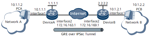
  • Network A is on the 10.1.1.0/24 subnet. Device A uses GigabitEthernet0/1/1 to connect to network A.

  • Network B is on the 10.1.2.0/24 subnet. Device B uses GigabitEthernet0/1/1 to connect to network B.

  • Routes between Device A and Device B are reachable.

The GRE over IPsec network is required to implement the following functions:
  • Transmits packets that are not supported by IPsec between PCA and PCB, such as multicast and broadcast packets.

  • Encrypts packets transmitted between PCA and PCB.

Configuration Roadmap

The configuration roadmap is as follows:

  1. Set a GRE tunnel between Device A and Device B so that multicast and broadcast packets can be encapsulated in the GRE tunnel.

  2. Set an IPsec tunnel between Device A and Device B so that GRE-encapsulated packets can be encrypted in the IPsec tunnel.

Data Preparation

To complete the configuration, you need the following data:

  • IP address of each interface
  • Tunneling modes, IP addresses, source IP addresses, and destination IP addresses of tunnel interfaces
  • IP address segment of each network
  • Preshared key
  • Security protocol, encryption algorithm, and authentication algorithm of an IPsec proposal
  • Authentication algorithm of an IKE proposal

Procedure

  • Configure Device A.
    1. Set IP addresses for interfaces.

      1. Set an IP address for GigabitEthernet 0/1/1.

        <DeviceA> system-view
        [~DeviceA] interface GigabitEthernet 0/1/1
        [~DeviceA-GigabitEthernet0/1/1] ip address 10.1.1.1 24
        [*DeviceA-GigabitEthernet0/1/1] quit
        [*DeviceA] commit
      2. Set an IP address for GigabitEthernet 0/1/2.

        [~DeviceA] interface GigabitEthernet 0/1/2
        [~DeviceA-GigabitEthernet0/1/2] ip address 172.16.163.1 24
        [*DeviceA-GigabitEthernet0/1/2] quit
        [*DeviceA] commit
      3. Set an IP address for Loopback 1.

        [~DeviceA] interface loopback1
        [*DeviceA-Loopback1] ip address 1.1.1.1 255.255.255.255 
        [*DeviceA-Loopback1] quit
        [*DeviceA] commit

    2. Configure the IPsec service instance group.

      [~DeviceA] service-location 1
      [*DeviceA-service-location-1] location slot 1
      [*DeviceA-service-location-1] commit
      [~DeviceA-service-location-1] quit
      [~DeviceA] service-instance-group group1
      [*DeviceA-service-instance-group-group1] service-location 1
      [*DeviceA-service-instance-group-group1] commit
      [~DeviceA-service-instance-group-group1] quit

    3. Create and configure tunnel interfaces.

      [~DeviceA] interface loopback1
      [*DeviceA-Loopback1] binding tunnel gre
      [*DeviceA-Loopback1] quit
      [~DeviceA] interface Tunnel 2
      [*DeviceA-Tunnel2] tunnel-protocol gre
      [*DeviceA-Tunnel2] ip address 172.21.1.1 24
      [*DeviceA-Tunnel2] source loopback1
      [*DeviceA-Tunnel2] destination 2.2.2.2
      [*DeviceA-Tunnel2] quit
      [*DeviceA] commit
      [~DeviceA] interface Tunnel 1
      [*DeviceA-Tunnel1] tunnel-protocol ipsec
      [*DeviceA-Tunnel1] ip address 172.19.1.1 24
      [*DeviceA-Tunnel1] quit
      [*DeviceA] commit

    4. Configure static routes to network B. This configuration example assumes that the next hop of Device A is 172.16.163.2/24.

      When configuring static routes to direct IPsec traffic into IPsec tunnels, specify an IPsec tunnel interface as the outbound interface of the static routes and specify a next hop address.

      [~DeviceA] ip route-static 10.1.2.2 255.255.255.255 Tunnel 2 2.2.2.2
      [*DeviceA] ip route-static 2.2.2.2 255.255.255.255 Tunnel 1 172.20.1.2
      [*DeviceA] ip route-static 172.20.1.2 255.255.255.255 172.16.163.2
      [*DeviceA] commit

    5. Configure an advanced ACL with the ID of 3000.

      [~DeviceA] acl 3000
      [*DeviceA-acl-adv-3000] rule permit gre source 1.1.1.1 0.0.0.0 destination 2.2.2.2 0.0.0.0
      [*DeviceA-acl-adv-3000] quit
      [*DeviceA] commit

    6. Configure an IPsec proposal with the name of tran1.

      [~DeviceA] ipsec proposal tran1
      [*DeviceA-ipsec-proposal-tran1] encapsulation-mode tunnel
      [*DeviceA-ipsec-proposal-tran1] transform esp
      [*DeviceA-ipsec-proposal-tran1] esp authentication-algorithm sha2-256
      [*DeviceA-ipsec-proposal-tran1] esp encryption-algorithm aes 256
      [*DeviceA-ipsec-proposal-tran1] quit
      [*DeviceA] commit

    7. Configure an IKE proposal with the ID of 10.

      [~DeviceA] ike proposal 10
      [*DeviceA-ike-proposal-10] authentication-method pre-share
      [*DeviceA-ike-proposal-10] authentication-algorithm sha2-256
      [*DeviceA-ike-proposal-10] integrity-algorithm hmac-sha2-256
      [*DeviceA-ike-proposal-10] dh group14
      [*DeviceA-ike-proposal-10] quit
      [*DeviceA] commit

    8. Configure an IKE peer with the name of b.

      • The setting of the pre-shared key should be identical with that on the peer device.

      [~DeviceA] ike peer b 
      [*DeviceA-ike-peer-b] ike-proposal 10 
      [*DeviceA-ike-peer-b] remote-address 172.20.1.2 
      [*DeviceA-ike-peer-b] pre-shared-key abcde 
      [*DeviceA-ike-peer-b] quit
      [*DeviceA] commit

    9. Configure an IPsec policy with the name of map1 and ID of 10.

      [~DeviceA] ipsec policy map1 10 isakmp
      [*DeviceA-ipsec-policy-isakmp-map1-10] security acl 3000
      [*DeviceA-ipsec-policy-isakmp-map1-10] proposal tran1
      [*DeviceA-ipsec-policy-isakmp-map1-10] ike-peer b
      [*DeviceA-ipsec-policy-isakmp-map1-10] quit
      [*DeviceA] commit

    10. Apply map1 to the tunnel interface.

      [~DeviceA] interface Tunnel 1
      [*DeviceA-Tunnel1] ipsec policy map1 service-instance-group group1
      [*DeviceA-Tunnel1] quit
      [*DeviceA] commit

  • Configure Device B.
    1. Set IP addresses for interfaces.

      1. Set an IP address for GigabitEthernet 0/1/1.

        <DeviceB> system-view
        [~DeviceB] interface GigabitEthernet 0/1/1
        [~DeviceB-GigabitEthernet0/1/1] ip address 10.1.2.1 24
        [*DeviceB-GigabitEthernet0/1/1] quit
        [*DeviceB] commit
      2. Set an IP address for GigabitEthernet 0/1/2.

        [~DeviceB] interface GigabitEthernet 0/1/2
        [~DeviceB-GigabitEthernet0/1/2] ip address 172.16.169.1 24
        [*DeviceB-GigabitEthernet0/1/2] quit
        [*DeviceB] commit
      3. Set an IP address for Loopback 1.

        [~DeviceB] interface loopback1
        [*DeviceB-Loopback1] ip address 2.2.2.2 255.255.255.255 
        [*DeviceB-Loopback1] quit
        [*DeviceB] commit

    2. Configure the IPsec service instance group.

      [~DeviceB] service-location 1
      [*DeviceB-service-location-1] location slot 1
      [*DeviceB-service-location-1] commit
      [~DeviceB-service-location-1] quit
      [~DeviceB] service-instance-group group1
      [*DeviceB-service-instance-group-group1] service-location 1
      [*DeviceB-service-instance-group-group1] commit
      [~DeviceB-service-instance-group-group1] quit

    3. Create and configure tunnel interfaces.

      [~DeviceB] interface loopback1
      [*DeviceB-Loopback1] binding tunnel gre
      [*DeviceB-Loopback1] quit
      [~DeviceB] interface Tunnel 2
      [*DeviceB-Tunnel2] tunnel-protocol gre
      [*DeviceB-Tunnel2] ip address 172.22.1.2 24
      [*DeviceB-Tunnel2] source loopback1
      [*DeviceB-Tunnel2] destination 1.1.1.1
      [*DeviceB-Tunnel2] quit
      [*DeviceB] commit
      [~DeviceB] interface Tunnel 1
      [*DeviceB-Tunnel1] tunnel-protocol ipsec
      [*DeviceB-Tunnel1] ip address 172.20.1.2 24
      [*DeviceB-Tunnel1] quit
      [*DeviceB] commit

    4. Configure static routes to network A. This configuration example assumes that the next hop of Device B is 172.16.169.2/24.

      When configuring static routes to direct IPsec traffic into IPsec tunnels, specify an IPsec tunnel interface as the outbound interface of the static routes and specify a next hop address.

      [~DeviceB] ip route-static 10.1.1.2 255.255.255.255 Tunnel 2 1.1.1.1
      [*DeviceB] ip route-static 1.1.1.1 255.255.255.255 Tunnel 1 172.19.1.1 
      [*DeviceB] ip route-static 172.19.1.1 255.255.255.255 172.16.169.2
      [*DeviceB] commit

    5. Configure an advanced ACL with the ID of 3000.

      [~DeviceB] acl 3000
      [*DeviceB-acl-adv-3000] rule permit gre source 2.2.2.2 0.0.0.0 destination 1.1.1.1 0.0.0.0
      [*DeviceB-acl-adv-3000] quit
      [*DeviceB] commit

    6. Configure an IPsec proposal with the name of tran1.

      [~DeviceB] ipsec proposal tran1
      [*DeviceB-ipsec-proposal-tran1] encapsulation-mode tunnel
      [*DeviceB-ipsec-proposal-tran1] transform esp
      [*DeviceB-ipsec-proposal-tran1] esp authentication-algorithm sha2-256
      [*DeviceB-ipsec-proposal-tran1] esp encryption-algorithm aes 256
      [*DeviceB-ipsec-proposal-tran1] quit
      [*DeviceB] commit

    7. Configure an IKE proposal with the ID of 10.

      [~DeviceB] ike proposal 10 
      [*DeviceB-ike-proposal-10] authentication-method pre-share 
      [*DeviceB-ike-proposal-10] authentication-algorithm sha2-256 
      [*DeviceB-ike-proposal-10] integrity-algorithm hmac-sha2-256
      [*DeviceB-ike-proposal-10] dh group14
      [*DeviceB-ike-proposal-10] quit
      [*DeviceB] commit

    8. Configure an IKE peer with the name of a.

      • The setting of the pre-shared key should be identical with that on the peer device.

      [~DeviceB] ike peer a 
      [*DeviceB-ike-peer-a] ike-proposal 10 
      [*DeviceB-ike-peer-a] remote-address 172.19.1.1 
      [*DeviceB-ike-peer-a] pre-shared-key abcde 
      [*DeviceB-ike-peer-a] quit
      [*DeviceB] commit

    9. Configure an IPsec policy with the name of map1 and ID of 10.

      [~DeviceB] ipsec policy map1 10 isakmp 
      [*DeviceB-ipsec-policy-isakmp-map1-10] security acl 3000 
      [*DeviceB-ipsec-policy-isakmp-map1-10] proposal tran1 
      [*DeviceB-ipsec-policy-isakmp-map1-10] ike-peer a 
      [*DeviceB-ipsec-policy-isakmp-map1-10] quit
      [*DeviceB] commit

    10. Apply map1 to the tunnel interface.

      [~DeviceB] interface Tunnel1 
      [*DeviceB-Tunnel1] ipsec policy map1 service-instance-group group1
      [*DeviceB-Tunnel1] quit
      [*DeviceB] commit

Configuration Files

  • Configurations on Device A

    #
     sysname DeviceA
    #
    acl number 3000
      rule 5 permit gre source 1.1.1.1 0 destination 2.2.2.2 0
    #
    service-location 1
     location slot 1
    #
    service-instance-group group1
     service-location 1
    #
    ike proposal 10
     encryption-algorithm aes-cbc 256
     dh group14
     authentication-algorithm sha2-256
     integrity-algorithm hmac-sha2-256
    #
    ike peer b
     pre-shared-key %$%$THBGMJK2659z"C(T{J"-,.2n%$%$
     ike-proposal 10
     remote-address 172.20.1.2
    #
    ipsec proposal tran1
     esp authentication-algorithm sha2-256
     esp encryption-algorithm aes 256
    #
    ipsec policy map1 10 isakmp
     security acl 3000
     ike-peer b
     proposal tran1
    #
    interface GigabitEthernet0/1/1
     undo shutdown
     ip address 10.1.1.1 255.255.255.0
    #
    interface GigabitEthernet0/1/2
     undo shutdown
     ip address 172.16.163.1 255.255.255.0
    #
    interface loopback1
     ip address 1.1.1.1 255.255.255.255
     binding tunnel gre
    #
    interface Tunnel1 
     ip address 172.19.1.1 255.255.255.0
     tunnel-protocol ipsec
     ipsec policy map1 service-instance-group group1
    #
    interface Tunnel2 
     ip address 172.21.1.1 255.255.255.0
     tunnel-protocol gre
     source loopback1
     destination 2.2.2.2
    #
     ip route-static 10.1.2.2 255.255.255.255 Tunnel 2 2.2.2.2
     ip route-static 2.2.2.2 255.255.255.255 Tunnel 1 172.20.1.2
     ip route-static 172.20.1.2 255.255.255.255 172.16.163.2
    #
    return
  • Configurations on Device B.

    #
     sysname DeviceB
    #
    acl number 3000
      rule 5 permit gre source 2.2.2.2 0 destination 1.1.1.1 0
    #
    service-location 1
     location slot 1
    #
    service-instance-group group1
     service-location 1
    #
    ike proposal 10
     encryption-algorithm aes-cbc 256
     dh group14
     authentication-algorithm sha2-256
     integrity-algorithm hmac-sha2-256
    #
    ike peer a
     pre-shared-key %$%$THBGMJK2659z"C(T{J"-,.2n%$%$
     ike-proposal 10
     remote-address 172.19.1.1
    #
    ipsec proposal tran1
     esp authentication-algorithm sha2-256
     esp encryption-algorithm aes 256
    #
    ipsec policy map1 10 isakmp
     security acl 3000
     ike-peer a
     proposal tran1
    #
    interface GigabitEthernet0/1/1
     undo shutdown
     ip address 10.1.2.1 255.255.255.0
    #
    interface GigabitEthernet0/1/2
     undo shutdown
     ip address 172.16.169.1 255.255.255.0
    #
    interface loopback1
     ip address 2.2.2.2 255.255.255.255
     binding tunnel gre
    #
    interface Tunnel1
     ip address 172.22.1.2 255.255.255.0
     tunnel-protocol ipsec
     ipsec policy map1 service-instance-group group1
    #
    interface Tunnel2
     ip address 172.20.1.2 255.255.255.0
     tunnel-protocol gre
     source loopback1
     destination 1.1.1.1
    #
     ip route-static 10.1.1.2 255.255.255.255 Tunnel 2 1.1.1.1
     ip route-static 1.1.1.1 255.255.255.255 Tunnel 1 172.19.1.1
     ip route-static 172.19.1.1 255.255.255.255 172.16.169.2
    #
    return
Copyright © Huawei Technologies Co., Ltd.
Next topic >