NS Multicast Suppression
Background
When a user is connected to an EVPN MPLS network through a BD, IPv6 host neighbors are discovered in NS multicast mode. When a device receives an NS message for IPv6 address resolution, the device forwards the NS message in multicast mode in its BD. If a large number of NS messages are received within a specified period, forwarding all these NS messages on the EVPN occupies excessive network resources, which affects service running.
NS multicast suppression is introduced to solve this problem. With NS multicast suppression enabled, upon receipt of an NS message, a device checks whether the NS message contains information about the end user. If such information is contained in the request message, the device simply implements proxy ND or converts multicast streams to unicast streams, thereby reducing or suppressing NS message flooding.
Usage Scenarios
On an EVPN MPLS network accessed through a BD, NS multicast suppression can be deployed to reduce or suppress NS message flooding, which alleviates network pressure and ensures normal service running.
Implementation
NS Multicast Suppression
The basic principle of NS multicast suppression is that the local device collects the local IPv6 host information and generates an ND table (with the outbound interface information contained) or a proxy ND table. Then, the local device uses EVPN routes to flood ND entries or proxy ND entries. Upon receipt of the flooded entries, the remote device generates a proxy ND table. In this manner, when the device receives NS messages again, it searches the local proxy ND table first. If the matching IPv6 host information exists, the local device simply implements proxy ND or converts multicast streams to unicast streams.

For Layer 2 devices, the function to generate a proxy ND table needs to be enabled in a BD so that the entries of a proxy ND table generated on the host can be flooded to a remote device through EVPN routes. For Layer 3 devices, the function to generate an ND table needs to be enabled on a VBDIF interface so that the entries of an ND table generated on the host can be flooded to a remote device through EVPN routes.
The implementation procedure for Layer 2 devices is similar to that for Layer 3 devices. The following example describes the implementation procedure for Layer 2 devices.
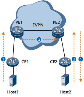
- Host1 goes online from PE1. On PE1, the function to generate a proxy ND table is enabled in a specified BD. A proxy ND table is generated for Host1 and the table entries are flooded to PE2 through EVPN routes.
- Upon receipt of the proxy ND entries flooded by PE1, PE2 abstracts the IPv6 host information and generates a proxy ND table for Host1.
- Host2 sends an NS multicast message to PE2 to request for the MAC address which is on the same network segment as Host1.
- PE2 searches the local proxy ND table based on the destination IPv6 address of the NS multicast message and locates the MAC address of Host1. Based on the user configuration, PE2 constructs a unicast NA message as a reply to Host2 or converts the NS multicast message to an NS unicast message before forwarding it.
Upon receipt of the NS unicast message converted from an NS multicast message, Host1 replies with an NA unicast message. Upon receipt of the NA unicast message, Host2 can obtain the MAC address of Host1.
Derivative Function
Defense Against ND Spoofing Attacks
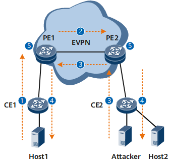
The enabling of NS multicast suppression can prevent against ND spoofing attacks. An ND spoofing attack means that an attacker associates its MAC address with the IPv6 address of a host so that any traffic destined for the IPv6 address can be sent to the attacker. With NS multicast suppression enabled, if such an attack is launched, the proxy ND table conflict detection mechanism triggers an IPv6 address conflict alarm, reminding users of the potential ND spoofing attack.
As shown in Figure 2, the following describes the implementation procedure of defense against ND spoofing attacks.
For Layer 2 devices, the function to generate a proxy ND table needs to be enabled in a BD so that the entries of a proxy ND table generated on the host can be flooded to a remote device through EVPN routes. For Layer 3 devices, the function to generate an ND table needs to be enabled on a VBDIF interface so that the entries of an ND table generated on the host can be flooded to a remote device through EVPN routes.
The implementation procedure for Layer 2 devices is similar to that for Layer 3 devices. The following example describes the implementation procedure for Layer 2 devices.
- Host1 goes online from PE1. On PE1, the function to generate a proxy ND table is enabled in a specified BD. A proxy ND table is generated for Host1 and the table entries are flooded to PE2 through EVPN routes.
- Upon receipt of the proxy ND entries flooded by PE1, PE2 abstracts the IPv6 host information and generates a proxy ND table for Host1.
- The attacker goes online from PE2. A proxy ND table for Host1 is generated on PE2 and the table entries are flooded to PE1 through EVPN routes. Upon receipt of the proxy ND entries flooded by PE2, PE1 abstracts the IPv6 host information and generates a proxy ND table for Host1.
- In this case, on both PE1 and PE2, the proxy ND table synchronized through EVPN routes and the local proxy ND table have the same IPv6 address. Neighbor unreachability detection (NUD) is triggered on PE1 and PE2.
- If PE1 or PE2 detects that the MAC address corresponding to the IPv6 address is changed multiple times within a specified period, an IPv6 conflict alarm is generated. This is a reminder that an ND spoofing attack may occur.
Host Migration
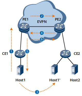
After NS multicast suppression is enabled, host migration is supported. As shown in Figure 3, the following describes the implementation procedure of host migration.
For Layer 2 devices, the function to generate a proxy ND table needs to be enabled in a BD so that the entries of a proxy ND table generated on the host can be flooded to a remote device through EVPN routes. For Layer 3 devices, the function to generate an ND table needs to be enabled on a VBDIF interface so that the entries of an ND table generated on the host can be flooded to a remote device through EVPN routes.
The implementation procedure for Layer 2 devices is similar to that for Layer 3 devices. The following example describes the implementation procedure for Layer 2 devices.
- Host1 goes online from PE1. On PE1, the function to generate a proxy ND table is enabled in a specified BD. A proxy ND table is generated for Host1 and the table entries are flooded to PE2 through EVPN routes.
- Upon receipt of the proxy ND entries flooded by PE1, PE2 abstracts the IPv6 host information and generates a proxy ND table for Host1.
- Host1 is migrated from CE1 to CE2 and proactively sends a gratuitous NA message.
- PE2 generates a proxy ND table for Host1 based on the gratuitous NA message and floods the table entries to PE1 through EVPN routes. Upon receipt of the proxy ND entries flooded by PE2, PE1 abstracts the IPv6 host information and generates a proxy ND table for Host1.
- PE1 discovers that Host1 recorded in the local proxy ND table is the local device and the next hop address is PE1's IP address. In the updated proxy ND table, the recorded Host1 is a remote device and the next hop address is PE2's IP address. This indicates that host migration may occur. Therefore, NUD is triggered on PE1. PE1 sends an NS message. As Host1 has been migrated from CE1 to CE2, PE1 fails to receive NA messages.
- PE1 detects that Host1 is unreachable and therefore deletes the old local proxy ND table and uses EVPN routes to notify PE2 of deleting the proxy ND table synchronized with Host1 upon PE1 access.