Example for Establishing LSPs Through LDP
This section provides an example for establishing LSPs using LDP. The configuration procedure involves establishing a local LDP session and modifying the policy for triggering the establishment of an LSP on each LSR.
Networking Requirements
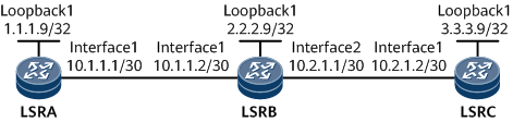
In Figure 1, LSRA, LSRB, and LSRC all function as core devices or edge devices on a backbone network. On this network, after local LDP sessions are set up between LSRA and LSRB, and between LSRB and LSRC, each pair of LSRs can distribute labels to each other and establish LDP LSPs. MPLS services can be transmitted along the LSPs.
Configuration Notes
When establishing LSPs through LDP, note the following:
Each LSR must have route entries that exactly match FECs for the LSPs to be established.
LDP by default uses 32-bit host routes to establish LSPs.
LDP can use all IGP routes except public BGP or default routes to establish LSPs.
Configuration Roadmap
The configuration roadmap is as follows:
Configure local LDP sessions.
Modify the policy for triggering the establishment of an LSP on each LSR.
Data Preparation
To complete the configuration, you need the following data:
IP address of each interface on each LSR as shown in Figure 1, OSPF process ID, and OSPF area ID
Policy for triggering the establishment of an LSP
Procedure
- Configure an LDP LSP.
After you complete the task described in the Example for Configuring Local LDP Sessions, each LSR runs LDP to establish an LSP using a host route with a 32-bit address mask.
# Run the display mpls ldp lsp command on an LSR. The command output shows that LDP has used all host routes to successfully establish LSPs.
The following example uses the command output on LSRA.
[~LSRA] display mpls ldp lsp

 LDP LSP Information
 -------------------------------------------------------------------------------
 Flag after Out IF: (I) - RLFA Iterated LSP, (I*) - Normal and RLFA Iterated LSP
 -------------------------------------------------------------------------------
 DestAddress/Mask   In/OutLabel    UpstreamPeer    NextHop          OutInterface
 -------------------------------------------------------------------------------
 1.1.1.9/32         3/NULL         2.2.2.9         127.0.0.1        LoopBack1
*1.1.1.9/32         Liberal/3                      DS/2.2.2.2
 2.2.2.9/32         NULL/3         -               10.1.1.2         GE0/1/0
 2.2.2.9/32         1024/3         2.2.2.9         10.1.1.2         GE0/1/0
 3.3.3.9/32         NULL/1025      -               10.1.1.2         GE0/1/0
 3.3.3.9/32         1025/1025      3.3.3.9         10.1.1.2         GE0/1/0
 ------------------------------------------------------------------------------
 TOTAL: 5 Normal LSP(s) Found.
 TOTAL: 1 Liberal LSP(s) Found.
 TOTAL: 0 Frr LSP(s) Found.
 An asterisk (*) before an LSP means the LSP is not established
 An asterisk (*) before a Label means the USCB or DSCB is stale
 An asterisk (*) before an UpstreamPeer means the session is stale
 An asterisk (*) before a DS means the session is stale
 An asterisk (*) before a NextHop means the LSP is FRR LSP

The default policy is used to enable LDP to use routes to host IP addresses with 32-bit masks to establish LSPs.
- Change the policy for triggering the establishment of LDP LSPs.
Modify the default policy and allow LDP to use all routes, including static and IGP routes in a routing table, to establish LSPs.
# Configure LSRA.
[~LSRA] mpls
[*LSRA-mpls] lsp-trigger all
[*LSRA-mpls] commit
[~LSRA-mpls] quit
# Configure LSRB.
[~LSRB] mpls
[*LSRB-mpls] lsp-trigger all
[*LSRB-mpls] commit
[~LSRB-mpls] quit
# Configure LSRC.
[~LSRC] mpls
[*LSRC-mpls] lsp-trigger all
[*LSRC-mpls] commit
[~LSRC-mpls] quit
- Verify the configuration.
# After completing the configuration, run the display mpls ldp lsp command on an LSR to view information about LDP LSPs.
The following example uses the command output on LSRA.
[~LSRA] display mpls ldp lsp
 LDP LSP Information
 -------------------------------------------------------------------------------
 Flag after Out IF: (I) - RLFA Iterated LSP, (I*) - Normal and RLFA Iterated LSP
 -------------------------------------------------------------------------------
 DestAddress/Mask   In/OutLabel   UpstreamPeer    NextHop     OutInterface
 -------------------------------------------------------------------------------
 1.1.1.9/32         3/NULL        2.2.2.9         127.0.0.1   LoopBack1
*1.1.1.9/32         Liberal/3                     DS/2.2.2.2
 2.2.2.9/32         NULL/3        -               10.1.1.2    GE0/1/0
 2.2.2.9/32         1024/3        2.2.2.9         10.1.1.2    GE0/1/0
 3.3.3.9/32         NULL/1025     -               10.1.1.2    GE0/1/0
 3.3.3.9/32         1025/1025     2.2.2.9         10.1.1.2    GE0/1/0
 10.1.1.0/30        3/NULL        2.2.2.9         10.1.1.1    GE0/1/0
*10.1.1.0/30        Liberal/3                     DS/2.2.2.2
 10.1.2.0/30        NULL/3        -               10.1.1.2    GE0/1/0
 10.1.2.0/30        1026/3        2.2.2.9         10.1.1.2    GE0/1/0
 -------------------------------------------------------------------------------
 TOTAL: 8 Normal LSP(s) Found.
 TOTAL: 2 Liberal LSP(s) Found.
 TOTAL: 0 Frr LSP(s) Found.
 An asterisk (*) before an LSP means the LSP is not established
 An asterisk (*) before a Label means the USCB or DSCB is stale
 An asterisk (*) before an UpstreamPeer means the session is stale
 An asterisk (*) before a DS means the session is stale
 An asterisk (*) before a NextHop means the LSP is FRR LSP
Configuration Files
LSRA configuration file
#
sysname LSRA
#
mpls lsr-id 1.1.1.9
#
mpls
  lsp-trigger all
#
mpls ldp
 #
 ipv4-family
#
interface GigabitEthernet0/1/0
 undo shutdown
 ip address 10.1.1.1 255.255.255.252
 mpls
 mpls ldp
#
interface LoopBack1
 ip address 1.1.1.9 255.255.255.255
#
ospf 1
 area 0.0.0.0
  network 1.1.1.9 0.0.0.0
  network 10.1.1.0 0.0.0.3
#
return
LSRB configuration file
#
 sysname LSRB
#
 mpls lsr-id 2.2.2.9
#
 mpls
  lsp-trigger all
#
mpls ldp
 #
 ipv4-family
#
interface GigabitEthernet0/1/0
 undo shutdown
 ip address 10.1.1.2 255.255.255.252
 mpls
 mpls ldp
#
interface GigabitEthernet0/1/8
 undo shutdown
 ip address 10.2.1.1 255.255.255.252
 mpls
 mpls ldp
#
interface LoopBack1
 ip address 2.2.2.9 255.255.255.255
#
ospf 1
 area 0.0.0.0
  network 2.2.2.9 0.0.0.0
  network 10.1.1.0 0.0.0.3
  network 10.2.1.0 0.0.0.3
#
return
LSRC configuration file
#
sysname LSRC
#
mpls lsr-id 3.3.3.9
#
mpls
  lsp-trigger all
#
mpls ldp
 #
 ipv4-family
#
interface GigabitEthernet0/1/0
 undo shutdown
 ip address 10.2.1.2 255.255.255.252
 mpls
 mpls ldp
#
interface LoopBack1
 ip address 3.3.3.9 255.255.255.255
#
ospf 1
 area 0.0.0.0
  network 3.3.3.9 0.0.0.0
  network 10.2.1.0 0.0.0.3
#
return