Example for Configuring an mLDP P2MP LSP
This section provides an example for configuring an mLDP P2MP LSP.
Networking Requirements
The mLDP P2MP technique is driven by the increasing demand to support the growing scale of multicast services on IP/MPLS backbone networks. A P2P LDP-enabled transmit end must replicate a packet and send it to multiple receive ends. Each replicated packet is sent along a separate LSP to its receive end, which wastes bandwidth resources. To address this problem, enable mLDP P2MP to establish P2MP LSPs, without the need to deploy Protocol Independent Multicast (PIM).
A tree-shaped mLDP P2MP LSP consists of sub-LSPs originating from the root node (ingress) and destined for leaf nodes. The root node directs multicast traffic to the P2MP LSP and sends packets to a branch node for replication. The branch node replicates the packets and forwards them to each leaf node connected to the branch node.
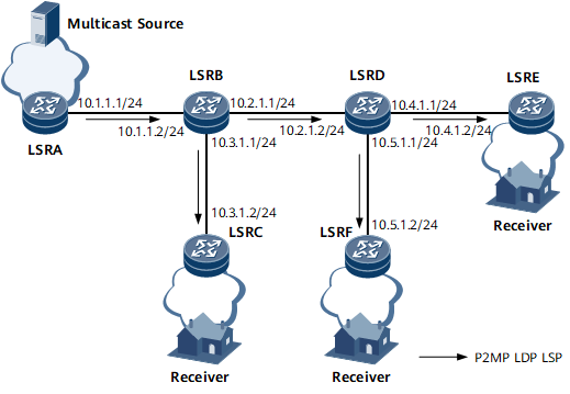
On the network shown in Figure 1, an mLDP P2MP LSP originates from root node LSRA and is destined for leaf nodes LSRC, LSRE, and LSRF.
Device Name |
Interface Name |
IP Address and Mask |
Device Name |
Interface Name |
IP Address and Mask |
|---|---|---|---|---|---|
LSRA |
GE 0/1/1 |
10.1.1.1/24 |
LSRE |
GE 0/1/0 |
10.4.1.2/24 |
Loopback1 |
1.1.1.1/32 |
Loopback1 |
5.5.5.5/32 |
||
LSRB |
GE 0/1/1 |
10.1.1.2/24 |
LSRD |
GE 0/1/0 |
10.2.1.2/24 |
GE 0/1/0 |
10.2.1.1/24 |
GE 0/1/2 |
10.4.1.1/24 |
||
GE 0/1/2 |
10.3.1.1/24 |
GE 0/1/1 |
10.5.1.1/24 |
||
Loopback1 |
2.2.2.2/32 |
Loopback1 |
4.4.4.4/32 |
||
LSRC |
GE 0/1/2 |
10.3.1.2/24 |
LSRF |
GE 0/1/1 |
10.5.1.2/24 |
Loopback1 |
3.3.3.3/32 |
Loopback1 |
6.6.6.6/32 |
Configuration Roadmap
The configuration roadmap is as follows:
Assign an address to each interface listed in Table 1.
Configure Intermediate System to Intermediate System (IS-IS) to advertise the route to each network segment to which each interface is connected and advertise the host route to each loopback interface address that is used as an LSR ID.
Set an MPLS LSR ID and globally enable MPLS, MPLS LDP, and mLDP P2MP on each node.
Configure MPLS LDP to establish a local LDP session on each interface along a P2MP LSP to be established.
Configure leaf nodes LSRC, LSRE, and LSRF to trigger LSP establishment.
Data Preparation
To complete the configuration, you need the following data:
IP address of each interface on every node listed in Table 1
IS-IS process ID (1) and IS-IS level (Level-2) on each node
Root node address (1.1.1.1), mLDP P2MP LSP name (lsp1), and LSP ID (1)
Procedure
- Assign an IP address to each interface.
Assign an IP address to each interface listed in Table 1 and create a loopback interface on each node. For configuration details, see Configuration Files in this section.
- Configure IS-IS to advertise the route to each network segment to which each interface is connected and to advertise the host route to each loopback address that is used as an LSR ID.
Configure IS-IS on each node to implement network layer connectivity. For configuration details, see Configuration Files in this section.
- Configure mLDP P2MP globally on each node.
Set an MPLS LSR ID and globally enable MPLS, MPLS LDP, and mLDP P2MP on each node.
# Configure LSRA.
[~LSRA] mpls lsr-id 1.1.1.1
[*LSRA] mpls
[*LSRA-mpls] mpls ldp
[*LSRA-mpls-ldp] mldp p2mp
[*LSRA-mpls-ldp] commit
[~LSRA-mpls-ldp] quit
Repeat this step for LSRB, LSRC, LSRD, LSRE, and LSRF. For configuration details, see Configuration Files in this section.
- Establish local LDP sessions between nodes.
Configure MPLS LDP on each directly connected interface to establish a local LDP session.
# Configure LSRA.
[~LSRA] interface gigabitethernet 0/1/1
[*LSRA-GigabitEthernet0/1/1] mpls
[*LSRA-GigabitEthernet0/1/1] mpls ldp
[*LSRA-GigabitEthernet0/1/1] commit
[~LSRA-GigabitEthernet0/1/1] quit
Repeat this step for LSRB, LSRC, LSRD, LSRE, and LSRF. For configuration details, see Configuration Files in this section.
- Configure leaf nodes LSRC, LSRE, and LSRF to trigger LSP establishment.
# Configure LSRC.
<LSRC> system-view
[~LSRC] mpls ldp
[*LSRC-mpls-ldp] mldp p2mp-lsp name lsp1 root-ip 1.1.1.1 lsp-id 1
[*LSRC-mpls-ldp] commit
[~LSRC-mpls-ldp] quit
# Configure LSRE.
<LSRE> system-view
[~LSRE] mpls ldp
[*LSRE-mpls-ldp] mldp p2mp-lsp name lsp1 root-ip 1.1.1.1 lsp-id 1
[*LSRE-mpls-ldp] commit
[~LSRE-mpls-ldp] quit
# Configure LSRF.
<LSRF> system-view
[~LSRF] mpls ldp
[*LSRF-mpls-ldp] mldp p2mp-lsp name lsp1 root-ip 1.1.1.1 lsp-id 1
[*LSRF-mpls-ldp] commit
[~LSRF-mpls-ldp] quit
- Verify the configuration.
# Run the ping multicast-lsp mldp p2mp root-ip 1.1.1.1 lsp-id 1 command on LSRA. The command output shows that the mLDP P2MP LSP is reachable.
[~LSRA] ping multicast-lsp mldp p2mp root-ip 1.1.1.1 lsp-id 1
  LSP PING FEC: root-ip 1.1.1.1 lsp-id 1 : 100  data bytes, press CTRL_C to break
    Reply from 3.3.3.3: bytes=100 Sequence=1 time=150 ms
    Reply from 5.5.5.5: bytes=100 Sequence=1 time=180 ms
    Reply from 6.6.6.6: bytes=100 Sequence=1 time=200 ms
    Reply from 3.3.3.3: bytes=100 Sequence=2 time=120 ms
    Reply from 5.5.5.5: bytes=100 Sequence=2 time=150 ms
    Reply from 6.6.6.6: bytes=100 Sequence=2 time=190 ms
    Reply from 3.3.3.3: bytes=100 Sequence=3 time=80 ms
    Reply from 6.6.6.6: bytes=100 Sequence=3 time=80 ms
    Reply from 5.5.5.5: bytes=100 Sequence=3 time=110 ms
    Reply from 3.3.3.3: bytes=100 Sequence=4 time=100 ms
    Reply from 5.5.5.5: bytes=100 Sequence=4 time=130 ms
    Reply from 6.6.6.6: bytes=100 Sequence=4 time=160 ms
    Reply from 3.3.3.3: bytes=100 Sequence=5 time=110 ms
    Reply from 5.5.5.5: bytes=100 Sequence=5 time=140 ms
    Reply from 6.6.6.6: bytes=100 Sequence=5 time=140 ms

    round-trip min/avg/max = 80/136/200 ms
# Run the display mpls mldp lsp p2mp command on LSRB. The command output shows that mLDP P2MP LSP information is consistent with the configuration.
<LSRB> display mpls mldp lsp p2mp
 An asterisk (*) before a Label means the USCB or DSCB is stale
 An asterisk (*) before a Peer means the session is stale
 -------------------------------------------------------------------------------
                        LSP Information: mLDP P2MP-LSP
 -------------------------------------------------------------------------------
 Root IP        : 1.1.1.1              Instance         : --
 Opaque decoded : LSP-ID 1
 Opaque value   : 01 0004 00000001
 Lsr Type       : Transit
 Trigger Type   : --
 Upstream Count : 1                    Downstream Count : 2
 Upstream:
   In Label  Peer              MBB State
       4101  1.1.1.1           --
 Downstream:
   Out Label Peer              MBB State     Next Hop        Out Interface
        4101 4.4.4.4           --            10.2.1.2        GigabitEthernet0/1/0
        4101 3.3.3.3           --            10.3.1.2        GigabitEthernet0/1/2
Configuration Files
LSRA configuration file
#
sysname LSRA
#
mpls lsr-id 1.1.1.1
#
mpls
#
mpls ldp
 mldp p2mp
 #
 ipv4-family
#
isis 1
 is-level level-2
 network-entity 00.0005.0000.0000.0001.00
#
interface GigabitEthernet0/1/1
 undo shutdown
 ip address 10.1.1.1 255.255.255.0
 isis enable 1
 mpls
 mpls ldp
#
interface LoopBack1
 ip address 1.1.1.1 255.255.255.255
 isis enable 1
#
return
LSRB configuration file
#
sysname LSRB
#
mpls lsr-id 2.2.2.2
#
mpls
#
mpls ldp
 mldp p2mp
 #
 ipv4-family
#
isis 1
 is-level level-2
 network-entity 00.0005.0000.0000.0002.00
#
interface GigabitEthernet0/1/0
 undo shutdown
 ip address 10.2.1.1 255.255.255.0
 isis enable 1
 mpls
 mpls ldp
#
interface GigabitEthernet0/1/2
 undo shutdown
 ip address 10.3.1.1 255.255.255.0
 isis enable 1
 mpls
 mpls ldp
#
interface GigabitEthernet0/1/1
 undo shutdown
 ip address 10.1.1.2 255.255.255.0
 isis enable 1
 mpls
 mpls ldp
#
interface LoopBack1
 ip address 2.2.2.2 255.255.255.255
 isis enable 1
#
return
LSRC configuration file
#
sysname LSRC
#
mpls lsr-id 3.3.3.3
#
mpls
#
mpls ldp
 mldp p2mp
 #
 ipv4-family
  mldp p2mp-lsp name lsp1 root-ip 1.1.1.1 lsp-id 1
#
isis 1
 is-level level-2
 network-entity 00.0005.0000.0000.0003.00
#
interface GigabitEthernet0/1/2
 undo shutdown
 ip address 10.3.1.2 255.255.255.0
 isis enable 1
 mpls
 mpls ldp
#
interface LoopBack1
 ip address 3.3.3.3 255.255.255.255
 isis enable 1
#
return
LSRD configuration file
#
sysname LSRD
#
mpls lsr-id 4.4.4.4
#
mpls
#
mpls ldp
 mldp p2mp
 #
 ipv4-family
#
isis 1
 is-level level-2
 network-entity 00.0005.0000.0000.0004.00
#
interface GigabitEthernet0/1/0
 undo shutdown
 ip address 10.2.1.2 255.255.255.0
 isis enable 1
 mpls
 mpls ldp
#
interface GigabitEthernet0/1/2
 undo shutdown
 ip address 10.4.1.1 255.255.255.0
 isis enable 1
 mpls
 mpls ldp
#
interface GigabitEthernet0/1/1
 undo shutdown
 ip address 10.5.1.1 255.255.255.0
 isis enable 1
 mpls
 mpls ldp
#
interface LoopBack1
 ip address 4.4.4.4 255.255.255.255
 isis enable 1
#
return
LSRE configuration file
#
sysname LSRE
#
mpls lsr-id 5.5.5.5
#
mpls
#
mpls ldp
 mldp p2mp
 #
 ipv4-family
  mldp p2mp-lsp name lsp1 root-ip 1.1.1.1 lsp-id 1
#
isis 1
 is-level level-2
 network-entity 00.0005.0000.0000.0005.00
#
interface GigabitEthernet0/1/0
 undo shutdown
 ip address 10.4.1.2 255.255.255.0
 isis enable 1
 mpls
 mpls ldp
#
interface LoopBack1
 ip address 5.5.5.5 255.255.255.255
 isis enable 1
#
return
LSRF configuration file
#
sysname LSRF
#
mpls lsr-id 6.6.6.6
#
mpls
#
mpls ldp
 mldp p2mp
 #
 ipv4-family
  mldp p2mp-lsp name lsp1 root-ip 1.1.1.1 lsp-id 1
#
isis 1
 is-level level-2
 network-entity 00.0005.0000.0000.0006.00
#
interface GigabitEthernet0/1/1
 undo shutdown
 ip address 10.5.1.2 255.255.255.0
 isis enable 1
 mpls
 mpls ldp
#
interface LoopBack1
 ip address 6.6.6.6 255.255.255.255
 isis enable 1
#
return