Example for Configuring LDP over TE
This section provides an example for configuring LDP over TE. The configuration procedure involves the establishment of a TE tunnel and a remote LDP peer.
Networking Requirements
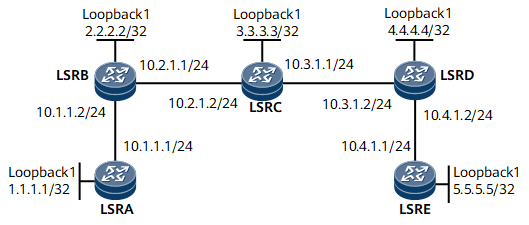
On the network shown in Figure 1, LSRB and LSRD are on the edge of a backbone network. LDP over TE is to be deployed on this network to allow an LDP LSP to across an RSVP-TE area. LDP services can be transmitted between LSRA and LSRB, and between LSRD and LSRE. In addition, TE services are transmitted between LSR B, LSRC, and between LSRC and LSRD. A TE tunnel destined for LSRD is established on LSRB, and an RSVP tunnel destined for LSRB is established on LSRD. Traffic between LSRA and LSRE needs to be transmitted through the tunnel. LDP over TE can transmit VPN services.
Device Name |
Interface Name |
IP Address |
|---|---|---|
LSRA |
Loopback1 |
1.1.1.1/32 |
GigabitEthernet0/1/0 |
10.1.1.1/24 |
|
LSRB |
Loopback1 |
2.2.2.2/32 |
GigabitEthernet0/1/0 |
10.1.1.2/24 |
|
GigabitEthernet0/1/8 |
10.2.1.1/24 |
|
LSRC |
Loopback1 |
3.3.3.3/32 |
GigabitEthernet0/1/0 |
10.2.1.2/24 |
|
GigabitEthernet0/1/8 |
10.3.1.1/24 |
|
LSRD |
Loopback1 |
4.4.4.4/32 |
GigabitEthernet0/1/0 |
10.3.1.2/24 |
|
GigabitEthernet0/1/8 |
10.4.1.2/24 |
|
LSRE |
Loopback1 |
5.5.5.5/32 |
GigabitEthernet0/1/0 |
10.4.1.1/24 |
Configuration Notes
When configuring LDP over TE, note that the tunnel destination address must be the LSR ID of the egress.
Configuration Roadmap
The configuration roadmap is as follows:
Assign an IP address to each interface, configure the loopback address as the LSR ID, configure an IGP to advertise routes to the network segment connected to each interface and the host route to each LSR ID.
Enable OSPF TE in a TE-aware area and establish an MPLS TE tunnel.
Enable MPLS LDP in each non-TE-aware area and configure remote LDP peers at the edge of the TE-aware area.
Configure the forwarding adjacency.
Data Preparation
To complete the configuration, you need the following data:
OSPF process ID and OSPF area ID
Policy for triggering the LSP establishment
Name and IP address of each remote LDP peer of LSRB and LSRD
Link bandwidth attributes of the tunnel
Tunnel interface number, IP address, destination address, tunnel ID, RSVP-TE tunnel signaling protocol, tunnel bandwidth, TE metric value, link cost on LSRB and LSRD
Procedure
- Assign an IP address to each interface.
Assign an IP address to each interface in this section. For configuration details, see Configuration Files in this section.
- Configure OSPF to advertise the route to the network segment to which each interface is connected and the host route to each LSR ID. For configuration details, see Configuration Files in this section.
- Enable MPLS on each LSR. Enable LDP to set up LDP sessions between LSRA and LSRB, and between LSRD and LSRE. Enable RSVP TE to establish RSVP neighbor relationships between LSRB and LSRC, and between LSRC and LSRD.
# Configure LSRA.
[~LSRA] mpls lsr-id 1.1.1.1
[*LSRA] mpls
[*LSRA-mpls] quit
[*LSRA] mpls ldp
[*LSRA-mpls-ldp] quit
[*LSRA] interface gigabitethernet 0/1/0
[*LSRA-GigabitEthernet0/1/0] mpls
[*LSRA-GigabitEthernet0/1/0] mpls ldp
[*LSRA-GigabitEthernet0/1/0] commit
[~LSRA-GigabitEthernet0/1/0] quit
# Configure LSRB.
[~LSRB] mpls lsr-id 2.2.2.2
[*LSRB] mpls
[*LSRB-mpls] mpls te
[*LSRB-mpls] mpls rsvp-te
[*LSRB-mpls] mpls te cspf
[*LSRB-mpls] quit
[*LSRB] mpls ldp
[*LSRB-mpls-ldp] quit
[*LSRB] interface gigabitethernet 0/1/0
[*LSRB-GigabitEthernet0/1/0] mpls
[*LSRB-GigabitEthernet0/1/0] mpls ldp
[*LSRB-GigabitEthernet0/1/0] quit
[*LSRB] interface gigabitethernet 0/1/8
[*LSRB-GigabitEthernet0/1/8] mpls
[*LSRB-GigabitEthernet0/1/8] mpls te
[*LSRB-GigabitEthernet0/1/8] mpls rsvp-te
[*LSRB-GigabitEthernet0/1/8] commit
[~LSRB-GigabitEthernet0/1/8] quit
# Configure LSRC.
[~LSRC] mpls lsr-id 3.3.3.3
[*LSRC] mpls
[*LSRC-mpls] mpls te
[*LSRC-mpls] mpls rsvp-te
[*LSRC-mpls] quit
[*LSRC] interface gigabitethernet 0/1/0
[*LSRC-GigabitEthernet0/1/0] mpls
[*LSRC-GigabitEthernet0/1/0] mpls te
[*LSRC-GigabitEthernet0/1/0] mpls rsvp-te
[*LSRC-GigabitEthernet0/1/0] quit
[*LSRC] interface gigabitethernet 0/1/8
[*LSRC-GigabitEthernet0/1/8] mpls
[*LSRC-GigabitEthernet0/1/8] mpls te
[*LSRC-GigabitEthernet0/1/8] mpls rsvp-te
[*LSRC-GigabitEthernet0/1/8] commit
[~LSRC-GigabitEthernet0/1/8] quit
# Configure LSRD.
[~LSRD] mpls lsr-id 4.4.4.4
[*LSRD] mpls
[*LSRD-mpls] mpls te
[*LSRD-mpls] mpls rsvp-te
[*LSRD-mpls] mpls te cspf
[*LSRD-mpls] quit
[*LSRD] mpls ldp
[*LSRD-mpls-ldp] quit
[*LSRD] interface gigabitethernet 0/1/0
[*LSRD-GigabitEthernet0/1/0] mpls
[*LSRD-GigabitEthernet0/1/0] mpls te
[*LSRD-GigabitEthernet0/1/0] mpls rsvp-te
[*LSRD-GigabitEthernet0/1/0] quit
[*LSRD] interface gigabitethernet 0/1/8
[*LSRD-GigabitEthernet0/1/8] mpls
[*LSRD-GigabitEthernet0/1/8] mpls ldp
[*LSRD-GigabitEthernet0/1/8] commit
[~LSRD-GigabitEthernet0/1/8] quit
# Configure LSRE.
[~LSRE] mpls lsr-id 5.5.5.5
[*LSRE] mpls
[*LSRE-mpls] quit
[*LSRE] mpls ldp
[*LSRE-mpls-ldp] quit
[*LSRE] interface gigabitethernet 0/1/0
[*LSRE-GigabitEthernet0/1/0] mpls
[*LSRE-GigabitEthernet0/1/0] mpls ldp
[*LSRE-GigabitEthernet0/1/0] commit
[~LSRE-GigabitEthernet0/1/0] quit
After the preceding configurations are complete, the local LDP sessions are successfully set up between LSRA and LSRB, and between LSRD and LSRE.
# Run the display mpls ldp session command on LSRA, LSRB, LSRD, or LSRE to view information about the established LDP session. The following example uses the command output on LSRA.
[~LSRA] display mpls ldp session
 LDP Session(s) in Public Network
 Codes: LAM(Label Advertisement Mode), SsnAge Unit(DDDD:HH:MM)
 A '*' before a session means the session is being deleted.
--------------------------------------------------------------------------
 PeerID             Status      LAM  SsnRole  SsnAge       KASent/Rcv
--------------------------------------------------------------------------
 2.2.2.2:0          Operational DU   Passive  0000:00:05   23/23
--------------------------------------------------------------------------
TOTAL: 1 Session(s) Found.
# Run the display mpls ldp peer command on an LSR to view information about the established LDP peer. The following example uses the command output on LSRA.
[~LSRA] display mpls ldp peer
 LDP Peer Information in Public network
 An asterisk (*) before a peer means the peer is being deleted.
 -------------------------------------------------------------------------
 PeerID                 TransportAddress   DiscoverySource
 -------------------------------------------------------------------------
 2.2.2.2:0              2.2.2.2            GigabitEthernet0/1/0
 -------------------------------------------------------------------------
TOTAL: 1 Peer(s) Found.
# Run the display mpls lsp command on an LSR. You can view information about LDP LSPs and RSVP tunnels are not set up. The following example uses the command output on LSRA.
[~LSRA] display mpls lsp
Flag after Out IF: (I) - RLFA Iterated LSP, (I*) - Normal and RLFA Iterated LSP
Flag after LDP FRR: (L) - Logic FRR LSP
-------------------------------------------------------------------------------
                 LSP Information: LDP LSP
-------------------------------------------------------------------------------
FEC                In/Out Label    In/Out IF                      Vrf Name
1.1.1.1/32         3/NULL          -/-
2.2.2.2/32         NULL/3          -/GE0/1/0
2.2.2.2/32         32841/3         -/GE0/1/0
- Configure a remote LDP session between LSRB and LSRD.
# Configure LSRB.
[~LSRB] mpls ldp remote-peer lsrd
[*LSRB-mpls-ldp-remote-lsrd] remote-ip 4.4.4.4
[*LSRB-mpls-ldp-remote-lsrd] commit
[~LSRB-mpls-ldp-remote-lsrd] quit
# Configure LSRD.
[~LSRD] mpls ldp remote-peer lsrb
[*LSRD-mpls-ldp-remote-lsrb] remote-ip 2.2.2.2
[*LSRD-mpls-ldp-remote-lsrb] commit
[~LSRD-mpls-ldp-remote-lsrb] quit
# After completing the preceding configurations, run the display mpls ldp remote-peer command on LSRB or LSRD. The commando output shows that a remote LDP session has been established between LSRB and LSRD. The following example uses the command output on LSRB.
[~LSRB] display mpls ldp remote-peer lsrd
                         LDP Remote Entity Information
 ------------------------------------------------------------------------------
 Remote Peer Name  : lsrd
 Description       : ----
 Remote Peer IP    : 4.4.4.4              LDP ID        : 2.2.2.2:0
 Transport Address : 2.2.2.2              Entity Status : Active

 Configured Keepalive Hold Timer : 45 Sec
 Configured Keepalive Send Timer : ----
 Configured Hello Hold Timer     : 45 Sec
 Negotiated Hello Hold Timer     : 45 Sec
 Configured Hello Send Timer     : ----
 Configured Delay Timer          : 10 Sec
 Hello Packet sent/received      : 425/382
 Label Advertisement Mode        : Downstream Unsolicited
 Auto-config                     : ----
 Manual-config                   : effective
 Session-Protect effect          : YES
 Session-Protect Duration        : infinite
 Session-Protect Remain          : ----
 ------------------------------------------------------------------------------
 TOTAL: 1 Remote-Peer(s) Found.
- Configure bandwidth attributes on each outbound interface along the link of the TE tunnel.
# Configure LSRB.
[~LSRB] interface gigabitethernet 0/1/8
[~LSRB-GigabitEthernet0/1/8] mpls te bandwidth max-reservable-bandwidth 20000
[*LSRB-GigabitEthernet0/1/8] mpls te bandwidth bc0 20000
[*LSRB-GigabitEthernet0/1/8] commit
[~LSRB-GigabitEthernet0/1/8] quit
# Configure LSRC.
[~LSRC] interface gigabitethernet 0/1/0
[~LSRC-GigabitEthernet0/1/0] mpls te bandwidth max-reservable-bandwidth 20000
[*LSRC-GigabitEthernet0/1/0] mpls te bandwidth bc0 20000
[*LSRC-GigabitEthernet0/1/0] quit
[*LSRC] interface gigabitethernet 0/1/8
[*LSRC-GigabitEthernet0/1/8] mpls te bandwidth max-reservable-bandwidth 20000
[*LSRC-GigabitEthernet0/1/8] mpls te bandwidth bc0 20000
[*LSRC-GigabitEthernet0/1/8] commit
[~LSRC-GigabitEthernet0/1/8] quit
# Configure LSRD.
[~LSRD] interface gigabitethernet 0/1/0
[~LSRD-GigabitEthernet0/1/0] mpls te bandwidth max-reservable-bandwidth 20000
[*LSRD-GigabitEthernet0/1/0] mpls te bandwidth bc0 20000
[*LSRD-GigabitEthernet0/1/0] commit
[~LSRD-GigabitEthernet0/1/0] quit
- Configure a tunnel from LSRB to LSRD.
# On LSRB, enable the forwarding adjacency on the tunnel interface and adjust the metric value of the forwarding adjacency to direct traffic destined for LSRD or LSRE to the tunnel.
[~LSRB] interface tunnel1
[*LSRB-Tunnel1] ip address unnumbered interface LoopBack1
[*LSRB-Tunnel1] tunnel-protocol mpls te
[*LSRB-Tunnel1] destination 4.4.4.4
[*LSRB-Tunnel1] mpls te tunnel-id 100
[*LSRB-Tunnel1] mpls te bandwidth ct0 10000
[*LSRB-Tunnel1] mpls te igp advertise
[*LSRB-Tunnel1] mpls te igp metric absolute 1
[*LSRB-Tunnel1] quit
[*LSRB] ospf 1
[*LSRB-ospf-1] opaque-capability enable
[*LSRB-ospf-1] area 0
[*LSRB-ospf-1-area-0.0.0.0] mpls-te enable
[*LSRB-ospf-1-area-0.0.0.0] quit
[*LSRB-ospf-1] enable traffic-adjustment advertise
[*LSRB-ospf-1] commit
- Configure a tunnel from LSRD to LSRB.
# On LSRD, enable the forwarding adjacency on the tunnel interface and adjust the metric value of the forwarding adjacency to direct traffic destined for LSRA or LSRB to the tunnel.
[~LSRD] interface tunnel1
[*LSRD-Tunnel1] ip address unnumbered interface LoopBack1
[*LSRD-Tunnel1] tunnel-protocol mpls te
[*LSRD-Tunnel1] destination 2.2.2.2
[*LSRD-Tunnel1] mpls te tunnel-id 101
[*LSRD-Tunnel1] mpls te bandwidth ct0 10000
[*LSRD-Tunnel1] mpls te igp advertise
[*LSRD-Tunnel1] mpls te igp metric absolute 1
[*LSRD-Tunnel1] quit
[*LSRD] ospf 1
[*LSRD-ospf-1] opaque-capability enable
[*LSRD-ospf-1] area 0
[*LSRD-ospf-1-area-0.0.0.0] mpls-te enable
[*LSRD-ospf-1-area-0.0.0.0] quit
[*LSRD-ospf-1] enable traffic-adjustment advertise
[*LSRD-ospf-1] commit
- Verify the configuration.
# After completing the preceding configurations, run the display mpls te tunnel-interface command on LSRB. The command output shows that the tunnels have been successfully established.
[~LSRB] display mpls te tunnel-interface
    Tunnel Name       : Tunnel1
    Signalled Tunnel Name: -
    Tunnel State Desc : CR-LSP is Up
    Tunnel Attributes   :
    Active LSP          : Primary LSP
    Traffic Switch      : -
    Session ID          : 100
    Ingress LSR ID      : 2.2.2.2               Egress LSR ID: 4.4.4.4
    Admin State         : UP                    Oper State   : UP
    Signaling Protocol  : RSVP
    FTid                : 1
    Tie-Breaking Policy : None                  Metric Type  : None
# Run the display ip routing-table command on LSRB to view route information. The command output shows that the outbound interfaces destined for LSRD and LSRE are tunnel interfaces.
[~LSRB] display ip routing-table
Route Flags: R - relay, D - download to fib, T - to vpn-instance, B - black hole route ------------------------------------------------------------------------------
Routing Table : _public_
         Destinations : 18       Routes : 19

Destination/Mask    Proto   Pre  Cost        Flags NextHop         Interface

        1.1.1.1/32  OSPF    10   1             D  10.1.1.1        GigabitEthernet0/1/0
        2.2.2.2/32  Direct  0    0             D  127.0.0.1       LoopBack1
        3.3.3.3/32  OSPF    10   1             D  10.2.1.2        GigabitEthernet0/1/8
        4.4.4.4/32  OSPF    10   1             D  2.2.2.2         Tunnel1
        5.5.5.5/32  OSPF    10   2             D  2.2.2.2         Tunnel1
       10.1.1.0/24  Direct  0    0             D  10.1.1.2        GigabitEthernet0/1/0
       10.1.1.1/32  Direct  0    0             D  10.1.1.1        GigabitEthernet0/1/0
       10.1.1.2/32  Direct  0    0             D  127.0.0.1       GigabitEthernet0/1/0
     10.1.1.255/32  Direct  0    0             D  127.0.0.1       GigabitEthernet0/1/0
       10.2.1.0/24  Direct  0    0             D  10.2.1.1        GigabitEthernet0/1/8
       10.2.1.1/32  Direct  0    0             D  127.0.0.1       GigabitEthernet0/1/8
     10.2.1.255/32  Direct  0    0             D  127.0.0.1       GigabitEthernet0/1/8
       10.3.1.0/24  OSPF    10   2             D  2.2.2.2         Tunnel1
                    OSPF    10   2             D  10.2.1.2        GigabitEthernet0/1/8
       10.4.1.0/24  OSPF    10   2             D  2.2.2.2         Tunnel1
      127.0.0.0/8   Direct  0    0             D  127.0.0.1       InLoopBack0
      127.0.0.1/32  Direct  0    0             D  127.0.0.1       InLoopBack0
127.255.255.255/32  Direct  0    0             D  127.0.0.1       InLoopBack0
255.255.255.255/32  Direct  0    0             D  127.0.0.1       InLoopBack0
# Run the display mpls lsp command on LSRB, LSRC, or LSRD to view information about LSPs. You can view information about RSVP LSPs. The following example uses the command output on LSRB.
[~LSRB] display mpls lsp
Flag after Out IF: (I) - RLFA Iterated LSP, (I*) - Normal and RLFA Iterated LSP
Flag after LDP FRR: (L) - Logic FRR LSP
-------------------------------------------------------------------------------
                 LSP Information: RSVP LSP
-------------------------------------------------------------------------------
FEC                In/Out Label    In/Out IF                      Vrf Name
4.4.4.4/32         NULL/32832      -/GE0/1/8
2.2.2.2/32         3/NULL          GE0/1/8/-
-------------------------------------------------------------------------------
                 LSP Information: LDP LSP
-------------------------------------------------------------------------------
FEC                In/Out Label    In/Out IF                      Vrf Name
1.1.1.1/32         NULL/3          -/GE0/1/0
1.1.1.1/32         32834/3         -/GE0/1/0
2.2.2.2/32         3/NULL          -/-
4.4.4.4/32         NULL/3          -/Tun1
4.4.4.4/32         32844/3         -/Tun1
5.5.5.5/32         NULL/32837      -/Tun1
5.5.5.5/32         32845/32837     -/Tun1
# Run the display ip routing-table command to view the routing table on LSRA. The command output shows that the cost values change after the forwarding adjacency was configured.
[~LSRA] display ip routing-table
Route Flags: R - relay, D - download to fib, T - to vpn-instance, B - black hole route ------------------------------------------------------------------------------
Routing Table : _public_
         Destinations : 16       Routes : 16

Destination/Mask    Proto   Pre  Cost        Flags NextHop         Interface

        1.1.1.1/32  Direct  0    0             D  127.0.0.1       LoopBack1
        2.2.2.2/32  OSPF    10   1             D  10.1.1.2        GigabitEthernet0/1/0
        3.3.3.3/32  OSPF    10   2             D  10.1.1.2        GigabitEthernet0/1/0
        4.4.4.4/32  OSPF    10   2             D  10.1.1.2        GigabitEthernet0/1/0
        5.5.5.5/32  OSPF    10   3             D  10.1.1.2        GigabitEthernet0/1/0
       10.1.1.0/24  Direct  0    0             D  10.1.1.1        GigabitEthernet0/1/0
       10.1.1.1/32  Direct  0    0             D  127.0.0.1       GigabitEthernet0/1/0
       10.1.1.2/32  Direct  0    0             D  10.1.1.2        GigabitEthernet0/1/0
     10.1.1.255/32  Direct  0    0             D  127.0.0.1       GigabitEthernet0/1/0
       10.2.1.0/24  OSPF    10   2             D  10.1.1.2        GigabitEthernet0/1/0
       10.3.1.0/24  OSPF    10   3             D  10.1.1.2        GigabitEthernet0/1/0
       10.4.1.0/24  OSPF    10   3             D  10.1.1.2        GigabitEthernet0/1/0
      127.0.0.0/8   Direct  0    0             D  127.0.0.1       InLoopBack0
      127.0.0.1/32  Direct  0    0             D  127.0.0.1       InLoopBack0
127.255.255.255/32  Direct  0    0             D  127.0.0.1       InLoopBack0
255.255.255.255/32  Direct  0    0             D  127.0.0.1       InLoopBack0
Configuration Files
LSRA configuration file
#
sysname LSRA
#
mpls lsr-id 1.1.1.1
#
mpls
#
mpls ldp
 #
 ipv4-family
#
interface GigabitEthernet0/1/0
 undo shutdown
 ip address 10.1.1.1 255.255.255.0
 mpls
 mpls ldp
#
interface LoopBack1
 ip address 1.1.1.1 255.255.255.255
#
ospf 1
 area 0.0.0.0
  network 1.1.1.1 0.0.0.0
  network 10.1.1.0 0.0.0.255
#
return
LSRB configuration file
#
sysname LSRB
#
mpls lsr-id 2.2.2.2
#
mpls
  mpls te
  mpls rsvp-te
  mpls te cspf
#
mpls ldp
 #
 ipv4-family
#
mpls ldp remote-peer lsrd
 remote-ip 4.4.4.4
#
interface GigabitEthernet0/1/0
 undo shutdown
 ip address 10.1.1.2 255.255.255.0
 mpls
 mpls ldp
#
interface GigabitEthernet0/1/8
 undo shutdown
 ip address 10.2.1.1 255.255.255.0
 mpls
 mpls te
 mpls te bandwidth max-reservable-bandwidth 20000
 mpls te bandwidth bc0 20000
 mpls rsvp-te
#
interface LoopBack1
 ip address 2.2.2.2 255.255.255.255
#
interface Tunnel1
 ip address unnumbered interface LoopBack1
 tunnel-protocol mpls te
 destination 4.4.4.4
 mpls te tunnel-id 100
 mpls te bandwidth ct0 10000
 mpls te igp advertise
 mpls te igp metric absolute 1
#
ospf 1
 opaque-capability enable
 enable traffic-adjustment advertise
 area 0.0.0.0
  network 2.2.2.2 0.0.0.0
  network 10.1.1.0 0.0.0.255
  network 10.2.1.0 0.0.0.255
  mpls-te enable
#
return
LSRC configuration file
#
sysname LSRC
#
mpls lsr-id 3.3.3.3
#
mpls
  mpls te
  mpls rsvp-te
#
interface GigabitEthernet0/1/0
 undo shutdown
 ip address 10.2.1.2 255.255.255.0
 mpls
 mpls te
 mpls te bandwidth max-reservable-bandwidth 20000
 mpls te bandwidth bc0 20000
 mpls rsvp-te
#
interface GigabitEthernet0/1/8
 undo shutdown
 ip address 10.3.1.1 255.255.255.0
 mpls
 mpls te
 mpls te bandwidth max-reservable-bandwidth 20000
 mpls te bandwidth bc0 20000
 mpls rsvp-te
#
interface LoopBack1
 ip address 3.3.3.3 255.255.255.255
#
ospf 1
 opaque-capability enable
 area 0.0.0.0
  network 3.3.3.3 0.0.0.0
  network 10.2.1.0 0.0.0.255
  network 10.3.1.0 0.0.0.255
  mpls-te enable
#
return
LSRD configuration file
#
sysname LSRD
#
mpls lsr-id 4.4.4.4
#
mpls
  mpls te
  mpls rsvp-te
  mpls te cspf
#
mpls ldp
 #
 ipv4-family
#
mpls ldp remote-peer lsrb
 remote-ip 2.2.2.2
#
interface GigabitEthernet0/1/0
 undo shutdown
 ip address 10.3.1.2 255.255.255.0
 mpls
 mpls te
 mpls te bandwidth max-reservable-bandwidth 20000
 mpls te bandwidth bc0 20000
 mpls rsvp-te
#
interface GigabitEthernet0/1/8
 undo shutdown
 ip address 10.4.1.2 255.255.255.0
 mpls
 mpls ldp
#
interface LoopBack1
 ip address 4.4.4.4 255.255.255.255
#
interface Tunnel1
 ip address unnumbered interface LoopBack1
 tunnel-protocol mpls te
 destination 2.2.2.2
 mpls te tunnel-id 101
 mpls te bandwidth ct0 10000
 mpls te igp advertise
 mpls te igp metric absolute 1
#
ospf 1
 opaque-capability enable
 enable traffic-adjustment advertise
 area 0.0.0.0
  network 4.4.4.4 0.0.0.0
  network 10.3.1.0 0.0.0.255
  network 10.4.1.0 0.0.0.255
  mpls-te enable
#
return
LSRE configuration file
#
sysname LSRE
#
mpls lsr-id 5.5.5.5
#
mpls
#
mpls ldp
 #
 ipv4-family
#
interface GigabitEthernet0/1/0
 undo shutdown
 ip address 10.4.1.2 255.255.255.0
 mpls
 mpls ldp
#
interface LoopBack1
 ip address 5.5.5.5 255.255.255.255
#
ospf 1
 area 0.0.0.0
  network 5.5.5.5 0.0.0.0
  network 10.4.1.0 0.0.0.255
#
return