Example for Configuring LDP Extension for Inter-Area LSPs
This section provides an example for configuring LDP extension for inter-area LSPs. The procedure involves enabling global MPLS and MPLS LDP and configuring a policy for aggregating routes.
Networking Requirements
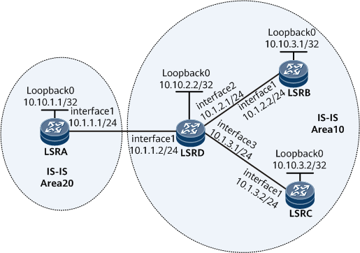
On the network shown in Figure 1, there are two IGP areas, Area 10 and Area 20. Inter-area LSPs need to be established from LSRA to LSRB and from LSRA to LSRC. An inter-area LSP needs to be configured on LSRA so that LSRA can search for routes based on the longest match rule to establish LSPs.

Configuration Roadmap
The configuration roadmap is as follows:
Assign IP addresses to interfaces on each node and configure the loopback addresses that are used as LSR IDs.
Enable IS-IS.
Configure the policy for aggregating routes.
Enable global and interface-based MPLS and MPLS LDP on each node.
Configure LDP extension for inter-area LSPs.
Data Preparation
To complete the configuration, you need the following data:
IP address of each interface, as shown in Figure 1
IS-IS area ID of each node and level of each node and interface
Procedure
- Assign IP addresses to interfaces on each node and configure the loopback addresses that are used as LSR IDs.
Assign an IP address and a mask to each interface, including a loopback interface, according to Figure 1. For configuration details, see Configuration Files in this section.
- Enable IS-IS.
# Configure LSRA.
<~LSRA> system-view
[~LSRA] isis 1
[*LSRA-isis-1] is-level level-2
[*LSRA-isis-1] network-entity 20.0010.0100.0001.00
[*LSRA-isis-1] quit
[*LSRA] interface gigabitethernet 0/1/0
[*LSRA-Gigabitethernet0/1/0] isis enable 1
[*LSRA-Gigabitethernet0/1/0] quit
[*LSRA] interface loopback 0
[*LSRA-LoopBack0] isis enable 1
[*LSRA-LoopBack0] commit
[~LSRA-LoopBack0] quit
# Configure LSRD.
<~LSRD> system-view
[~LSRD] isis 1
[*LSRD-isis-1] network-entity 10.0010.0200.0001.00
[*LSRD-isis-1] quit
[*LSRD] interface gigabitethernet 0/1/0
[*LSRD-Gigabitethernet0/1/0] isis enable 1
[*LSRD-Gigabitethernet0/1/0] isis circuit-level level-2
[*LSRD-Gigabitethernet0/1/0] quit
[*LSRD] interface gigabitethernet 0/1/1
[*LSRD-Gigabitethernet0/1/1] isis enable 1
[*LSRD-Gigabitethernet0/1/1] isis circuit-level level-1
[*LSRD-Gigabitethernet0/1/1] quit
[*LSRD] interface gigabitethernet 0/1/2
[*LSRD-Gigabitethernet0/1/2] isis enable 1
[*LSRD-Gigabitethernet0/1/2] isis circuit-level level-1
[*LSRD-Gigabitethernet0/1/2] quit
[*LSRD] interface loopback 0
[*LSRD-LoopBack0] isis enable 1
[*LSRD-LoopBack0] commit
[~LSRD-LoopBack0] quit
# Configure LSRB.
<~LSRB> system-view
[~LSRB] isis 1
[*LSRB-isis-1] is-level level-1
[*LSRB-isis-1] network-entity 10.0010.0300.0001.00
[*LSRB-isis-1] quit
[*LSRB] interface gigabitethernet 0/1/0
[*LSRB-Gigabitethernet0/1/0] isis enable 1
[*LSRB-Gigabitethernet0/1/0] quit
[*LSRB] interface loopback 0
[*LSRB-LoopBack0] isis enable 1
[*LSRB-LoopBack0] commit
[~LSRB-LoopBack0] quit
# Configure LSRC.
<~LSRC> system-view
[~LSRC] isis 1
[*LSRC-isis-1] is-level level-1
[*LSRC-isis-1] network-entity 10.0010.0300.0002.00
[*LSRC-isis-1] quit
[*LSRC] interface gigabitethernet 0/1/0
[*LSRC-Gigabitethernet0/1/0] isis enable 1
[*LSRC-Gigabitethernet0/1/0] quit
[*LSRC] interface loopback 0
[*LSRC-LoopBack0] isis enable 1
[*LSRC-LoopBack0] commit
[~LSRC-LoopBack0] quit
# On LSRA, run the display ip routing-table command to view routing information.
[~LSRA] display ip routing-table
Route Flags: R - relay, D - download to fib, T - to vpn-instance, B - black hole route
------------------------------------------------------------------------------
Routing Table: Public
         Destinations : 9        Routes : 9

Destination/Mask    Proto    Pre  Cost        Flags NextHop         Interface

      10.10.1.1/32  Direct   0    0             D  127.0.0.1       LoopBack0
      10.10.2.2/32  ISIS-L1  15   10            D  10.1.1.2        Gigabitethernet0/1/0
      10.10.3.1/32  ISIS-L1  15   20            D  10.1.1.2        Gigabitethernet0/1/0
      10.10.3.2/32  ISIS-L1  15   20            D  10.1.1.2        Gigabitethernet0/1/0
       10.1.1.0/24  Direct   0    0             D  10.1.1.1        Gigabitethernet0/1/0
       10.1.1.1/32  Direct   0    0             D  127.0.0.1       Gigabitethernet0/1/0
       10.1.1.2/32  Direct   0    0             D  10.1.1.2        Gigabitethernet0/1/0
      127.0.0.0/8   Direct   0    0             D  127.0.0.1       InLoopBack0
      127.0.0.1/32  Direct   0    0             D  127.0.0.1       InLoopBack0
- Configure the policy for aggregating routes.
# On LSRD, run the summary command to obtain the aggregated LSRB and LSRC host route.
[~LSRD] isis 1
[*LSRD-isis-1] summary 10.10.3.0 255.255.255.0 avoid-feedback
[*LSRD-isis-1] commit
[~LSRD-isis-1] quit
# On LSRA, run the display ip routing-table command to view routing information.
Route Flags: R - relay, D - download to fib, T - to vpn-instance, B - black hole route
------------------------------------------------------------------------------
Routing Table: Public
         Destinations : 8        Routes : 8

Destination/Mask    Proto    Pre  Cost        Flags NextHop         Interface

      10.10.1.1/32  Direct   0    0             D  127.0.0.1       LoopBack0
      10.10.2.2/32  ISIS-L1  15   10            D  10.1.1.2        Gigabitethernet0/1/0
     10.10.3.0/24 ISIS-L1 15  20           D  10.1.1.2      Gigabitethernet0/1/0
       10.1.1.0/24  Direct   0    0             D  10.1.1.1        Gigabitethernet0/1/0
       10.1.1.1/32  Direct   0    0             D  127.0.0.1       Gigabitethernet0/1/0
       10.1.1.2/32  Direct   0    0             D  10.1.1.2        Gigabitethernet0/1/0
      127.0.0.0/8   Direct   0    0             D  127.0.0.1       InLoopBack0
      127.0.0.1/32  Direct   0    0             D  127.0.0.1       InLoopBack0
The command output shows that the host routes to LSRB and LSRC have been aggregated.
- Configure global and interface-based MPLS and MPLS LDP on each node so that the network can forward MPLS traffic, and view the setup of the LSP.
# Configure LSRA.
[~LSRA] mpls lsr-id 10.10.1.1
[~LSRA] mpls
[*LSRA-mpls] quit
[*LSRA] mpls ldp
[*LSRA-mpls-ldp] quit
[*LSRA] interface gigabitethernet 0/1/0
[*LSRA-Gigabitethernet0/1/0] mpls
[*LSRA-Gigabitethernet0/1/0] mpls ldp
[*LSRA-Gigabitethernet0/1/0] commit
[~LSRA-Gigabitethernet0/1/0] quit
# Configure LSRD.
[~LSRD] mpls lsr-id 10.10.2.2
[~LSRD] mpls
[*LSRD-mpls] quit
[*LSRD] mpls ldp
[*LSRD-mpls-ldp] quit
[*LSRD] interface gigabitethernet 0/1/0
[*LSRD-Gigabitethernet0/1/0] mpls
[*LSRD-Gigabitethernet0/1/0] mpls ldp
[*LSRD-Gigabitethernet0/1/0] quit
[*LSRD] interface gigabitethernet 0/1/1
[*LSRD-Gigabitethernet0/1/1] mpls
[*LSRD-Gigabitethernet0/1/1] mpls ldp
[*LSRD-Gigabitethernet0/1/1] quit
[*LSRD] interface gigabitethernet 0/1/2
[*LSRD-Gigabitethernet0/1/2] mpls
[*LSRD-Gigabitethernet0/1/2] mpls ldp
[*LSRD-Gigabitethernet0/1/2] commit
[~LSRD-Gigabitethernet0/1/2] quit
# Configure LSRB.
[~LSRB] mpls lsr-id 10.10.3.1
[~LSRB] mpls
[*LSRB-mpls] quit
[*LSRB] mpls ldp
[*LSRB-mpls-ldp] quit
[*LSRB] interface gigabitethernet 0/1/0
[*LSRB-Gigabitethernet0/1/0] mpls
[*LSRB-Gigabitethernet0/1/0] mpls ldp
[*LSRB-Gigabitethernet0/1/0] commit
[~LSRB-Gigabitethernet0/1/0] quit
# Configure LSRC.
[~LSRC] mpls lsr-id 10.10.3.2
[~LSRC] mpls
[*LSRC-mpls] quit
[*LSRC] mpls ldp
[*LSRC-mpls-ldp] quit
[*LSRC] interface gigabitethernet 0/1/0
[*LSRC-Gigabitethernet0/1/0] mpls
[*LSRC-Gigabitethernet0/1/0] mpls ldp
[*LSRC-Gigabitethernet0/1/0] commit
[~LSRC-Gigabitethernet0/1/0] quit
# After completing the configuration, run the display mpls lsp command on LSRA to view the established LSP.
[~LSRA] display mpls lsp
Flag after Out IF: (I) - RLFA Iterated LSP, (I*) - Normal and RLFA Iterated LSP
Flag after LDP FRR: (L) - Logic FRR LSP
-------------------------------------------------------------------------------
                 LSP Information: LDP LSP
-------------------------------------------------------------------------------
FEC                In/Out Label  In/Out IF                      Vrf Name
10.10.2.2/32         NULL/3        -/Gigabitethernet0/1/0
10.10.2.2/32         1024/3        -/Gigabitethernet0/1/0
The preceding command output shows that by default, LDP does not establish the inter-area LSPs from LSRA to LSRB and from LSRA to LSRC.
- Configure LDP extension for inter-area LSPs.
# Run the longest-match command on LSRA to configure LDP to search for a route based on the longest match rule to establish an inter-area LDP LSP.
[~LSRA] mpls ldp
[*LSRA-mpls-ldp] longest-match
[*LSRA-mpls-ldp] commit
[~LSRA-mpls-ldp] quit
- Verify the configuration.
# After completing the preceding configuration, run the display mpls lsp command on LSRA to view the established LSP.
[~LSRA] display mpls lsp
Flag after Out IF: (I) - RLFA Iterated LSP, (I*) - Normal and RLFA Iterated LSP
Flag after LDP FRR: (L) - Logic FRR LSP
-------------------------------------------------------------------------------
                 LSP Information: LDP LSP
-------------------------------------------------------------------------------
FEC                In/Out Label  In/Out IF                      Vrf Name
10.10.2.2/32         NULL/3        -/Gigabitethernet0/1/0
10.10.2.2/32         1024/3        -/Gigabitethernet0/1/0
10.10.3.1/32       NULL/1025   -/Gigabitethernet0/1/0
10.10.3.1/32       1025/1025   -/Gigabitethernet0/1/0
10.10.3.2/32       NULL/1026   -/Gigabitethernet0/1/0
10.10.3.2/32       1026/1026   -/Gigabitethernet0/1/0
The preceding command output shows that LDP establishes the inter-area LSPs from LSRA to LSRB and from LSRA to LSRC.
Configuration Files
LSRA configuration file
#
 sysname LSRA
#
 mpls lsr-id 10.10.1.1
 mpls
#
mpls ldp
 longest-match
#
isis 1
 is-level level-2
 network-entity 20.0010.0100.0001.00
#
interface gigabitethernet0/1/0
undo shutdown
 ip address 10.1.1.1 255.255.255.0
 isis enable 1
 mpls
 mpls ldp
#
interface LoopBack0
 ip address 10.10.1.1 255.255.255.255
 isis enable 1
#
return
LSRD configuration file
#
 sysname LSRD
#
 mpls lsr-id 10.10.2.2
 mpls
#
mpls ldp
#
isis 1
 network-entity 10.0010.0200.0001.00
 import-route isis level-1 into level-2 filter-policy ip-prefix permit-host
 summary 10.10.3.0 255.255.255.0 avoid-feedback
#
interface gigabitethernet0/1/0
 undo shutdown
 ip address 10.1.1.2 255.255.255.0
 isis enable 1
 isis circuit-level level-2
 mpls
 mpls ldp
#
interface gigabitethernet0/1/1
 undo shutdown
 ip address 10.1.2.1 255.255.255.0
 isis enable 1
 isis circuit-level level-1
 mpls
 mpls ldp
#
interface gigabitethernet0/1/2
 undo shutdown
 ip address 10.1.3.1 255.255.255.0
 isis enable 1
 isis circuit-level level-1
 mpls
 mpls ldp
#
interface LoopBack0
 ip address 10.10.2.2 255.255.255.255
 isis enable 1
#
 ip ip-prefix permit-host index 10 permit 0.0.0.0 32
#
return
LSRB configuration file
#
 sysname LSRB
#
 mpls lsr-id 10.10.3.1
 mpls
#
mpls ldp
#
isis 1
 is-level level-1
 network-entity 10.0010.0300.0001.00
#
interface gigabitethernet0/1/0
 undo shutdown
 ip address 10.1.2.2 255.255.255.0
 isis enable 1
 mpls
 mpls ldp
#
interface LoopBack0
 ip address 10.10.3.1 255.255.255.255
 isis enable 1
#
return
LSRC configuration file
#
 sysname LSRC
#
 mpls lsr-id 10.10.3.2
 mpls
#
mpls ldp
#
isis 1
 is-level level-1
 network-entity 10.0010.0300.0002.00
#
interface gigabitethernet0/1/0
 undo shutdown
 ip address 10.1.3.2 255.255.255.0
 isis enable 1
 mpls
 mpls ldp
#
interface LoopBack0
 ip address 10.10.3.2 255.255.255.255
 isis enable 1
#
return