Example for Configuring Static BFD for LDP LSP
This section provides an example for configuring static BFD for LDP LSP. The configuration procedure involves enabling MPLS and MPLS LDP in the system and interface views and enabling BFD on two ends of a link to be monitored.
Networking Requirements
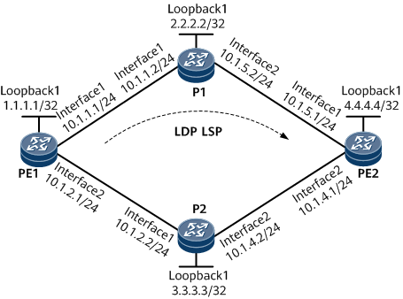
On the network shown in Figure 1, an LDP LSP is established over a path PE1 -> P1 -> PE2. The reverse path PE2 -> P1 -> PE1 is an IP path. Static BFD needs to be configured to detect faults in the LDP LSP.

Configuration Roadmap
The configuration roadmap is as follows:
Configure OSPF on the MPLS domain to implement network layer connectivity.
Establish an LDP LSP along the path PE1 -> P1 -> PE2.
Configure a BFD session and bind the BFD session to the LDP LSP on PE1.
Configure a BFD session and bind the BFD session to the IP path on PE2, allowing PE2 to notify PE1 of a fault if BFD detects a fault in the LDP LSP.
Data Preparation
To complete the configuration, you need the following data:
IP address of every interface
OSPF process ID
BFD configuration name and local and remote discriminators
Procedure
- Assign an IP address to each interface and configure OSPF.
Assign an IP address and its mask to each interface, such as a loopback interface according to Figure 1.
Configure OSPF on every node to advertise every host and network segment route. For configuration details, see Configuration Files in this section.
After completing the configurations, ping every node using a specific LSR ID. The ping is successful. Run the display ip routing-table command on every node. Routes to nodes in routing tables are reachable.
<PE1> display ip routing-table
Route Flags: R - relay, D - download to fib, T - to vpn-instance, B - black hole route
------------------------------------------------------------------------------
Routing Table : _public_
         Destinations : 16       Routes : 16

Destination/Mask    Proto  Pre  Cost        Flags NextHop         Interface

        1.1.1.1/32  Direct 0    0             D  127.0.0.1       LoopBack1
        2.2.2.2/32  OSPF   10   2             D  10.1.1.2        GigabitEthernet0/1/0
        3.3.3.3/32  OSPF   10   2             D  10.1.2.2        GigabitEthernet0/1/1
        4.4.4.4/32  OSPF   10   3             D  10.1.1.2        GigabitEthernet0/1/0
                    OSPF   10   3             D  10.1.2.2        GigabitEthernet0/1/1
       10.1.1.0/24  Direct 0    0             D  10.1.1.1        GigabitEthernet0/1/0
       10.1.1.1/32  Direct 0    0             D  127.0.0.1       GigabitEthernet0/1/0
     10.1.1.255/32  Direct 0    0             D  127.0.0.1       GigabitEthernet0/1/0
       10.1.2.0/24  Direct 0    0             D  10.1.2.1        GigabitEthernet0/1/1
       10.1.2.1/32  Direct 0    0             D  127.0.0.1       GigabitEthernet0/1/1
     10.1.2.255/32  Direct 0    0             D  127.0.0.1       GigabitEthernet0/1/1
       10.1.4.0/24  OSPF   10   3             D  10.1.2.2        GigabitEthernet0/1/1
       10.1.5.0/24  OSPF   10   3             D  10.1.1.2        GigabitEthernet0/1/0
      127.0.0.0/8   Direct 0    0             D  127.0.0.1       InLoopBack0
      127.0.0.1/32  Direct 0    0             D  127.0.0.1       InLoopBack0
127.255.255.255/32  Direct 0    0             D  127.0.0.1       InLoopBack0
255.255.255.255/32  Direct 0    0             D  127.0.0.1       InLoopBack0
- Establish an LDP LSP along the path PE1 -> P1 -> PE2.
# Configure PE1.
<PE1> system-view
[~PE1] mpls lsr-id 1.1.1.1
[*PE1] mpls
[*PE1-mpls] quit
[*PE1] mpls ldp
[*PE1-mpls] quit
[*PE1]interface gigabitethernet 0/1/0
[*PE1-GigabitEthernet0/1/0] mpls
[*PE1-GigabitEthernet0/1/0] mpls ldp
[*PE1-GigabitEthernet0/1/0] quit
[*PE1] commit
# Configure P1.
<P1> system-view
[~P1] mpls lsr-id 2.2.2.2
[*P1] mpls
[*P1-mpls] quit
[*P1] mpls ldp
[*P1-mpls] quit
[*P1]interface gigabitethernet 0/1/0
[*P1-GigabitEthernet0/1/0] mpls
[*P1-GigabitEthernet0/1/0] mpls ldp
[*P1-GigabitEthernet0/1/0] quit
[*P1]interface gigabitethernet 0/1/1
[*P1-GigabitEthernet0/1/1] mpls
[*P1-GigabitEthernet0/1/1] mpls ldp
[*P1-GigabitEthernet0/1/1] quit
[*P1] commit
# Configure PE2.
<PE2> system-view
[~PE2] mpls lsr-id 4.4.4.4
[*PE2] mpls
[*PE2-mpls] quit
[*PE2] mpls ldp
[*PE2-mpls] quit
[*PE2]interface gigabitethernet 0/1/0
[*PE2-GigabitEthernet0/1/0] mpls
[*PE2-GigabitEthernet0/1/0] mpls ldp
[*PE2-GigabitEthernet0/1/0] quit
[*PE2] commit
# Run the display mpls ldp lsp command. An LDP LSP destined for 4.4.4.4/32 has been established on PE1.
<PE1> display mpls ldp lsp
 LDP LSP Information
 -------------------------------------------------------------------------------
 Flag after Out IF: (I) - RLFA Iterated LSP, (I*) - Normal and RLFA Iterated LSP
 -------------------------------------------------------------------------------
 DestAddress/Mask   In/OutLabel    UpstreamPeer    NextHop          OutInterface
 -------------------------------------------------------------------------------
 1.1.1.1/32         3/NULL         2.2.2.2         127.0.0.1         LoopBack1
*1.1.1.1/32         Liberal/21                     DS/2.2.2.2
 2.2.2.2/32         NULL/3         -               10.1.1.2          GE0/1/0
 2.2.2.2/32         16/3           2.2.2.2         10.1.1.2          GE0/1/0
 4.4.4.4/32         NULL/22        -               10.1.1.2          GE0/1/0
 4.4.4.4/32         17/22          2.2.2.2         10.1.1.2          GE0/1/0
 -------------------------------------------------------------------------------
 TOTAL: 5 Normal LSP(s) Found.
 TOTAL: 1 Liberal LSP(s) Found.
 TOTAL: 0 Frr LSP(s) Found.
 An asterisk (*) before an LSP means the LSP is not established
 An asterisk (*) before a Label means the USCB or DSCB is stale
 An asterisk (*) before an UpstreamPeer means the session is stale
 An asterisk (*) before a DS means the session is stale
 An asterisk (*) before a NextHop means the LSP is FRR LSP
- Enable BFD globally on two nodes at the two ends of a link to be detected.
# Configure PE1.
<PE1> system-view
[~PE1] bfd
[*PE1-bfd] quit
[*PE1] commit
# Configure P2.
<PE2> system-view
[~PE2] bfd
[*PE2-bfd] quit
[*PE2] commit
- Configure a BFD session and bind the BFD session to the LDP LSP on the ingress.
# Configure PE1.
<PE1> system-view
[~PE1] bfd 1to4 bind ldp-lsp peer-ip 4.4.4.4 nexthop 10.1.1.2 interface gigabitethernet 0/1/0
[*PE1-bfd-lsp-session-1to4] discriminator local 1
[*PE1-bfd-lsp-session-1to4] discriminator remote 2
[*PE1-bfd-lsp-session-1to4] process-pst
[*PE1-bfd-lsp-session-1to4] commit
[~PE1-bfd-lsp-session-1to4] quit
- Configure a BFD session and bind the BFD session to the IP path on the egress, which allows the egress to notify the ingress of a fault if BFD detects a fault in the LDP LSP.
# Configure PE2.
<PE2> system-view
[~PE2] bfd 4to1 bind peer-ip 1.1.1.1
[*PE2-bfd-session-4ot1] discriminator local 2
[*PE2-bfd-session-4ot1] discriminator remote 1
[*PE2-bfd-session-4ot1] commit
[~PE2-bfd-session-4ot1] quit
- Verify the configuration.
# After completing the configuration, run the display bfd session all verbose command on the ingress. The State field displays Up, and the BFD Bind Type field displays LDP_LSP.
<PE1> display bfd session all verbose
(w): State in WTR
(*): State is invalid
--------------------------------------------------------------------------------
  State : Up                    Name : 1to4
--------------------------------------------------------------------------------
  Local Discriminator    : 1                Remote Discriminator   : 2
  Session Detect Mode    : Asynchronous Mode Without Echo Function
  BFD Bind Type          : LDP_LSP
  Bind Session Type      : Static
  Bind Peer IP Address   : 4.4.4.4
  NextHop Ip Address     : 10.1.1.2
  Bind Interface         : GigabitEthernet0/1/0
  Tunnel ID              : -
  FSM Board Id           : 3                TOS-EXP                : 7
  Min Tx Interval (ms)   : 10               Min Rx Interval (ms)   : 10
  Actual Tx Interval (ms): 10               Actual Rx Interval (ms): 10
  Local Detect Multi     : 3                Detect Interval (ms)   : 30
  Echo Passive           : Disable          Acl Number             : -
  Destination Port       : 3784             TTL                    : 1
  Proc Interface Status  : Disable          Process PST            : Enable
  WTR Interval (ms)      : -                Config PST             : Enable
  Active Multi           : 3
  Last Local Diagnostic  : No Diagnostic
  Bind Application       : No Application Bind
  Session TX TmrID       : -                Session Detect TmrID   : -
  Session Init TmrID     : -                Session WTR TmrID      : -
  Session Echo Tx TmrID  : -
  Session Description    : -
--------------------------------------------------------------------------------

    Total UP/DOWN Session Number : 1/0
Run the display bfd session all verbose command on the egress. The (Multi Hop) State field displays Up, and the BFD Bind Type field displays Peer IP Address.
<PE2> display bfd session all verbose
(w): State in WTR
(*): State is invalid
--------------------------------------------------------------------------------
  (Multi Hop) State : Up                    Name : 4to1
--------------------------------------------------------------------------------
  Local Discriminator    : 2                Remote Discriminator   : 1
  Session Detect Mode    : Asynchronous Mode Without Echo Function
  BFD Bind Type          : Peer IP Address
  Bind Session Type      : Static
  Bind Peer IP Address   : 1.1.1.1
  Bind Interface         : -
  Track Interface        : -
  Bind Source IP Address : 4.4.4.4
  FSM Board Id           : 3                TOS-EXP                : 7
  Min Tx Interval (ms)   : 10               Min Rx Interval (ms)   : 10
  Actual Tx Interval (ms): 10               Actual Rx Interval (ms): 10
  Local Detect Multi     : 3                Detect Interval (ms)   : 30
  Echo Passive           : Disable          Acl Number             : -
  Destination Port       : 3784             TTL                    : 254
  Proc Interface Status  : Disable          Process PST            : Disable
  WTR Interval (ms)      : -                Config PST             : Disable
  Active Multi           : 3
  Last Local Diagnostic  : No Diagnostic
  Bind Application       : No Application Bind
  Session TX TmrID       : -                Session Detect TmrID   : -
  Session Init TmrID     : -                Session WTR TmrID      : -
  Session Echo Tx TmrID  : -
  Session Description    : -
--------------------------------------------------------------------------------

    Total UP/DOWN Session Number : 1/0
Configuration Files
PE1 configuration file
#
 sysname PE1
#
 bfd
#
 mpls lsr-id 1.1.1.1
#
 mpls
#
mpls ldp
 #
 ipv4-family#
#
interface GigabitEthernet0/1/0
 undo shutdown
 ip address 10.1.1.1 255.255.255.0
 mpls
 mpls ldp
#
interface GigabitEthernet0/1/1
 undo shutdown
 ip address 10.1.2.1 255.255.255.0
#
interface LoopBack1
 ip address 1.1.1.1 255.255.255.255
#
ospf 1
 area 0.0.0.0
  network 1.1.1.1 0.0.0.0
  network 10.1.1.0 0.0.0.255
  network 10.1.2.0 0.0.0.255
#
bfd 1to4 bind ldp-lsp peer-ip 4.4.4.4 nexthop 10.1.1.2 interface GigabitEthernet0/1/0
 discriminator local 1
 discriminator remote 2
 process-pst
 #
return
PE2 configuration file
#
 sysname PE2
#
 bfd
#
 mpls lsr-id 4.4.4.4
#
 mpls
#
mpls ldp
 #
 ipv4-family#
#
interface GigabitEthernet0/1/0
 undo shutdown
 ip address 10.1.5.1 255.255.255.0
 mpls
 mpls ldp
#
interface GigabitEthernet0/1/1
 undo shutdown
 ip address 10.1.4.1 255.255.255.0
#
interface LoopBack1
 ip address 4.4.4.4 255.255.255.255
#
ospf 1
 area 0.0.0.0
  network 10.1.5.0 0.0.0.255
  network 10.1.4.0 0.0.0.255
  network 4.4.4.4 0.0.0.0
#
bfd 4to1 bind peer-ip 1.1.1.1
 discriminator local 2
 discriminator remote 1
#
return
P1 configuration
#
 sysname P1
#
 mpls lsr-id 2.2.2.2
#
 mpls
#
mpls ldp
 #
 ipv4-family#
#
interface GigabitEthernet0/1/0
 undo shutdown
 ip address 10.1.1.2 255.255.255.0
 mpls
 mpls ldp
#
interface GigabitEthernet0/1/1
 undo shutdown
 ip address 10.1.5.2 255.255.255.0
 mpls
 mpls ldp
#
interface LoopBack1
 ip address 2.2.2.2 255.255.255.255
#
ospf 1
 area 0.0.0.0
  network 2.2.2.2 0.0.0.0
  network 10.1.1.0 0.0.0.255
  network 10.1.5.0 0.0.0.255
return
P2 configuration file
#
 sysname P2
#
interface GigabitEthernet0/1/0
 undo shutdown
 ip address 10.1.2.2 255.255.255.0
#
interface GigabitEthernet0/1/1
 undo shutdown
 ip address 10.1.4.2 255.255.255.0
#
interface LoopBack1
 ip address 3.3.3.3 255.255.255.255
#
ospf 1
 area 0.0.0.0
  network 3.3.3.3 0.0.0.0
  network 10.1.4.0 0.0.0.255
  network 10.1.2.0 0.0.0.255
return