LDP-IGP Synchronization
Background
LDP-IGP synchronization is used to synchronize the status between LDP and an IGP to minimize the traffic loss time if a network fault triggers the LDP and IGP switching.
On a network with active and standby links, if the active link fails, IGP routes and an LSP are switched to the standby link. After the active link recovers, IGP routes are switched back to the active link before LDP convergence is complete. In this case, the LSP along the active link takes time to make preparations, such as adjacency restoration, before being established. As a result, LSP traffic is discarded. If an LDP session or adjacency between nodes fails on the active link, the LSP along the active link is deleted. However, the IGP still uses the active link, and as a result, LSP traffic cannot be switched to the standby link, and is continuously discarded.

LDP-IGP synchronization supports only OSPFv2 and IS-IS for IPv4.
According to the fundamentals of LDP-IGP synchronization, an IGP cost value is set to delay a route switchback until LDP convergence is complete. Before the LSP along the active link is established, the LSP along the standby link is retained, so that the traffic continues to be forwarded through the standby link. The backup LSP is torn down only after the primary LSP is established successfully.
LDP-IGP synchronization timers are as follows:
Hold-max-cost timer
Delay timer
Implementation
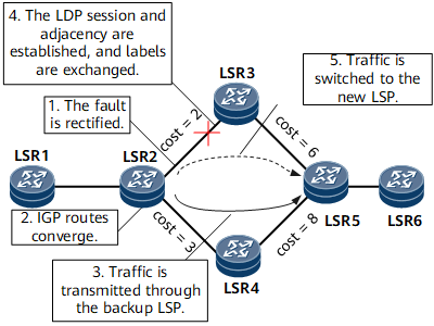
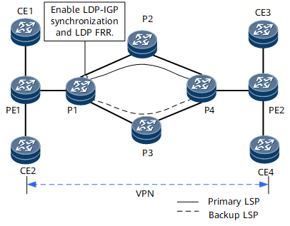
- In Figure 1, on a network with active and standby links, after the active link recovers, an attempt is made to switch traffic back from the standby link to the active link. Revertive traffic is discarded because the backup LSP becomes unavailable after the IGP convergence is complete but the primary LSP is not established. In this situation, you can configure LDP-IGP synchronization to delay the IGP route switchback until LDP convergence is complete. Before the primary LSP is converged, the backup LSP is retained, so that the traffic continues to be forwarded through the backup LSP until the primary LSP is successfully established. Then the backup LSP is torn down. The process is as follows:
A link fault is rectified.
An IGP advertises the maximum cost of the active link, delaying the IGP route switchback.
Traffic is still forwarded along the backup LSP.
After the LDP session and adjacency are successfully established, Label Mapping messages are exchanged to instruct the IGP to start synchronization.
The IGP advertises the normal cost of the active link and converges to the original path. The LSP is reestablished and the forwarding entries are delivered within milliseconds.
- If the LDP session or adjacency between nodes on the active link fails, the primary LSP is deleted, but the IGP still uses the active link. As a result, LSP traffic cannot be switched to the standby link, and traffic is continuously discarded. In this situation, you can configure LDP-IGP synchronization. If an LDP session or adjacency fails, LDP informs the IGP that the LDP session or adjacency is faulty. In this case, the IGP advertises the maximum cost of the faulty link. The route is switched to the standby link, and the LSP is also switched to the standby link. The process is as follows:
The LDP session or adjacency between nodes on the active link is faulty.
LDP informs the IGP that the LDP session or adjacency along the active link is faulty. The IGP then advertises the maximum cost of the active link.
IGP routes are switched to the standby link.
The LSP is reestablished along the standby link, and forwarding entries are delivered.
LDP-IGP synchronization state transition mechanism
After LDP-IGP synchronization is enabled on an interface, an IGP queries the status of related interfaces, LDP sessions, and LDP adjacencies based on the process shown in Figure 2. Then, the interface enters a state based on the query result. Then, the state transition is performed, as shown in Figure 2. When different IGP protocols are used, the preceding states are different.- When OSPF is used, the status transits based on the flowchart shown in Figure 2.
- When IS-IS is used, no Hold-normal-cost state is involved. After the Hold-Max-Cost timer expires, IS-IS advertises the normal cost value of the interface link, but the Hold-max-cost state is still displayed.

Usage Scenario
Benefits
LDP-IGP synchronization reduces the packet loss rate during an active/standby link switchover and improves the reliability of an entire network.