LDP Auto FRR
LDP auto fast reroute (FRR) backs up local interfaces to provide the fast reroute function for MPLS networks.
Background
On an MPLS network with both active and standby links, if an active link fails, IGP routes re-converge, and the IGP route of the standby link becomes reachable. An LDP LSP over the standby link is then established. During this process, some traffic is lost. To minimize traffic loss, LDP Auto FRR is used.
On the network enabled with LDP Auto FRR, if an interface failure (detected by the interface itself or by an associated BFD session) or a primary LSP failure (detected by an associated BFD session) occurs, LDP FRR is notified of the failure and rapidly forwards traffic to a backup LSP, protecting traffic on the primary LSP. The traffic switchover minimizes the traffic interruption time.
Implementation
LDP LFA FRR
LDP LFA FRR is implemented based on IGP LFA FRR's LDP Auto FRR. LDP LFA FRR uses the liberal label retention mode to obtain a liberal label, applies for a forwarding entry associated with the label, and forwards the forwarding entry to the forwarding plane as a backup forwarding entry to be used by the primary LSP. If an interface detects a failure of its own, bidirectional forwarding detection (BFD) detects an interface failure, or BFD detects a primary LSP failure, LDP LFA FRR rapidly switches traffic to a backup LSP to protect traffic on the primary LSP.
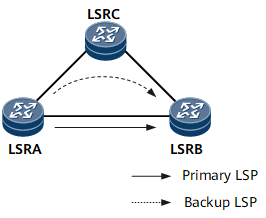
If the backup route corresponding to the source of the liberal label for LDP auto FRR exists, and its destination meets the policy for LDP to create a backup LSP. LSRA can apply a forwarding entry for the liberal label, establish a backup LSP as the backup forwarding entry of the primary LSP, and send the entries mapped to both the primary and backup LSPs to the forwarding plane. In this way, the primary LSP is associated with the backup LSP.
LDP Auto FRR is triggered when the interface detects faults by itself, BFD detects faults in the interface, or BFD detects a primary LSP failure. After LSP FRR is complete, traffic is switched to the backup LSP based on the backup forwarding entry. Then, the route is converged to LSRA-LSRC-LSRB. An LSP is established on the new LSP (the original backup LSP), and the original primary LSP is torn down, and then the traffic is forwarded along the new LSP over the path LSRA-LSRC-LSRB.
LDP Remote LFA FRR
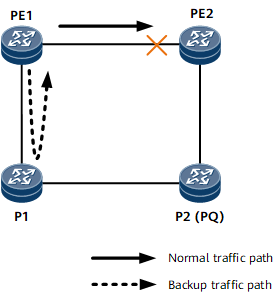
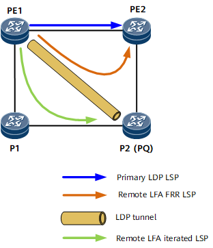
- An IGP uses the Remote LFA algorithm to calculate a Remote LFA route with the PQ node (P2) IP address and the recursive outbound interface's next hop and then notifies the route management module of the information. For the PQ node definition, see IS-IS Auto FRR.
- LDP obtains the Remote LFA route from the route management module. PE1 automatically establishes a remote LDP peer relationship with the PQ node and a remote LDP session for the relationship. PE1 then establishes an LDP LSP to the PQ node and a Remote LFA FRR LSP over the path PE1 -> P2 -> PE2. For information about how to automatically establish a remote LDP session, see LDP Session.
- LDP-enabled PE1 establishes an LDP LSP over the path PE1 -> P1 -> P2 with the recursive outbound interface's next hop. This LSP is called a Remote LFA FRR Recursion LSP.