mLDP In-Band MVPN Implementation
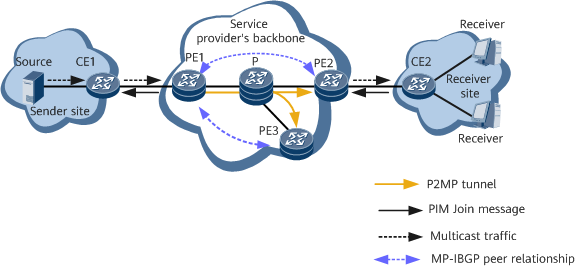
Figure 1 shows the typical networking of mLDP in-band MVPN, in which CE1 connects to the multicast source and CE2 connects to multicast receivers. mLDP in-band MVPN can be deployed on the ingress PE1 or egress PE2.
The Connector attribute is an optional transitive attribute of BGP and can be used to advertise root IP addresses of mLDP tunnels. mLDP in-band MVPN is implemented differently according to whether the VPNv4/EVPN route advertised by the ingress carries the Connector attribute. If the VPNv4/EVPN route advertised by the ingress carries the Connector attribute, the egress uses the IP address carried in the Connector attribute as the root IP address to instruct mLDP to create a tunnel. If the VPNv4/EVPN route advertised by the ingress does not carry the Connector or VRF Route Import Extended Community attribute, the egress uses the next hop address of the route as the root IP address to instruct mLDP to create a tunnel.
In an mLDP in-band MVPN scenario, you can determine whether to enable Connector attribute compatibility on the ingress. If Connector attribute compatibility is enabled, the Connector attribute is sent to the remote MP-BGP peer through BGP. If Connector attribute compatibility is disabled, the Connector attribute is withdrawn, and the VRF Route Import Extended Community attribute is sent to the remote MP-BGP peer through BGP.
For example, if CE2 sends a PIM (S, G) Join message, mLDP in-band MVPN is implemented as follows:
Scenario where the route advertised by the ingress carries the Connector attribute
Figure 2 shows the mLDP in-band MVPN data forwarding process in a scenario where the route advertised by the ingress carries the Connector attribute.

Step |
Device |
Key Action |
|---|---|---|
|
PE1 |
After receiving the unicast route to the multicast source from CE1, PE1 converts it to a VPNv4 route, encapsulates the Connector attribute into the VPNv4 route, and advertises the VPNv4 route to PE2. |
|
PE2 |
After receiving the route, PE2 matches it against import RTs of local VPN instances:
|
|
CE2 |
After obtaining a join request through IGMP, CE2 sends a PIM Join message containing an (S, G) entry to PE2 through PIM. |
|
PE2 |
After receiving the PIM Join message, PE2 subscribes to the remote route based on the S information in the PIM message, obtains the RD and root IP address (IP address carried in the Connector attribute), and encapsulates the (S, G) information in the PIM Join message and the obtained RD into the Opaque value of an mLDP Label Mapping message. It then instructs mLDP to establish an mLDP P2MP tunnel from PE2 to PE1. |
|
PE1 |
After receiving the mLDP Label Mapping message carrying the (S, G) information and the RD, PE1 extracts the (S, G) information and converts it into a PIM Join message. |
|
PE1 |
PE1 sends the PIM Join message to CE1 through PIM. |
|
CE1 |
After receiving the PIM Join message, CE1 generates a multicast routing entry, in which the downstream interface is the interface that receives the PIM Join message. At this point, the multicast receiver successfully joins the multicast group, and CE1 can send multicast traffic to CE2. |


Scenario where the route advertised by the ingress carries the VRF Route Import Extended Community attribute
Figure 3 shows the mLDP in-band MVPN data forwarding process in a scenario where the route advertised by the ingress carries the VRF Route Import Extended Community attribute.

Step |
Device |
Key Action |
|---|---|---|
|
PE1 |
After receiving the unicast route to the multicast source from CE1, PE1 converts it to a VPNv4 route and advertises the VPNv4 route to PE2. |
|
PE2 |
After receiving the route, PE2 matches it against import RTs of local VPN instances:
|
|
CE2 |
After obtaining a join request through IGMP, CE2 sends a PIM Join message containing an (S, G) entry to PE2 through PIM. |
|
PE2 |
After receiving the PIM Join message, PE2 subscribes to the remote route based on the S information in the PIM message, obtains the RD and root IP address (IP address carried in the VRF Route Import Extended Community attribute), and encapsulates the (S, G) information in the PIM Join message and the obtained RD into the Opaque value of an mLDP Label Mapping message. It then instructs mLDP to establish an mLDP P2MP tunnel from PE2 to PE1. |
|
PE1 |
After receiving the mLDP Label Mapping message carrying the (S, G) information and the RD, PE1 extracts the (S, G) information and converts it into a PIM Join message. |
|
PE1 |
PE1 sends the PIM Join message to CE1 through PIM. |
|
CE1 |
After receiving the PIM Join message, CE1 generates a multicast routing entry, in which the downstream interface is the interface that receives the PIM Join message. At this point, the multicast receiver successfully joins the multicast group, and CE1 can send multicast traffic to CE2. |


Scenario where the route advertised by the ingress does not carry the Connector attribute or VRF Route Import Extended Community attribute
Figure 4 shows the mLDP in-band MVPN data forwarding process in a scenario where the route advertised by the ingress does not carry the Connector attribute or VRF Route Import Extended Community attribute.

Step |
Device |
Key Action |
|---|---|---|
|
PE1 |
After receiving the unicast route to the multicast source from CE1, PE1 converts it to a VPNv4 route and advertises the VPNv4 route to PE2. |
|
CE2 |
After obtaining a join request through IGMP, CE2 sends a PIM Join message containing an (S, G) entry to PE2 through PIM. |
|
PE2 |
After receiving the PIM Join message, PE2 subscribes to the remote route based on the S information in the PIM message, obtains the RD and root IP address (next-hop IP address carried in the route) from the remote route, and encapsulates the (S, G) information in the PIM Join message and the obtained RD into the Opaque value of an mLDP Label Mapping message. It then instructs mLDP to establish an mLDP P2MP tunnel from PE2 to PE1. |
|
PE1 |
After receiving the mLDP Label Mapping message carrying the (S, G) information and the RD, PE1 extracts the (S, G) information and converts it into a PIM Join message. |
|
PE1 |
PE1 sends the PIM Join message to CE1 through PIM. |
|
CE1 |
After receiving the PIM Join message, CE1 generates a multicast routing entry, in which the downstream interface is the interface that receives the PIM Join message. At this point, the multicast receiver successfully joins the multicast group, and CE1 can send multicast traffic to CE2. |


