Example for Configuring BGP/MPLS IP VPN
After a BGP/MPLS IP VPN is configured, users in the same VPN can communicate with each other, but users in different VPNs cannot do so.
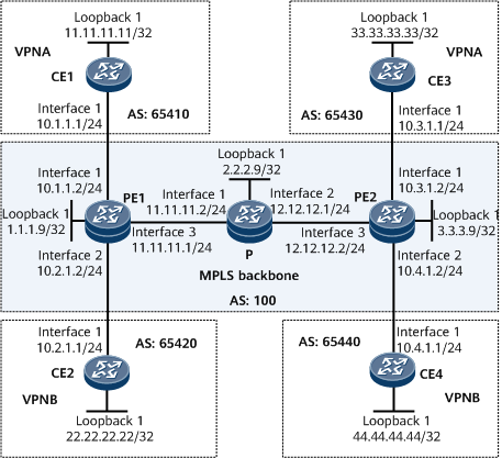
Networking Requirements
CE1 and CE3 belong to vpna.
CE2 and CE4 belong to vpnb.
The VPN target of vpna is 111:1; the VPN target of vpnb is 222:2.
It is required that users in the same VPN be able to communicate with each other, but users in different VPNs be unable to do so.
Configuration Notes
When configuring BGP/MPLS IP VPN, note the following:
On the same VPN, the export VPN target list of a site shares VPN targets with the import VPN target lists of the other sites. Conversely, the import VPN target list of a site shares VPN targets with the export VPN target lists of the other sites.
After a VPN instance is bound to a PE interface connected to a CE, Layer 3 configurations on this interface are automatically deleted. Such configurations include IP address and routing protocol configurations, and must be added again if necessary.
Configuration Roadmap
The configuration roadmap is as follows:
Enable OSPF on the backbone network to ensure that PEs interwork with each other.
Configure basic MPLS functions, enable MPLS LDP, and establish LDP LSPs on the backbone network.
Configure a VPN instance on each PE, create the IPv4 address family for the instance, and bind the interface that connects each PE to a CE to the VPN instance on that PE.
Enable Multi-protocol Extensions for Interior Border Gateway Protocol (MP IBGP) on PEs to exchange VPN routing information.
Configure EBGP on CEs and PEs to exchange VPN routing information.
Data Preparation
To complete the configuration, you need the following data:
MPLS LSR IDs on the PEs and the P
RDs of vpna and vpnb
VPN targets of vpna and vpnb
Procedure
- Configure an IGP on the MPLS backbone network to achieve connectivity between the PEs and P. OSPF is used as an IGP in this example.
# Configure PE1.
[~HUAWEI] sysname PE1
[*HUAWEI] commit
[~PE1] interface loopback 1
[*PE1-LoopBack1] ip address 1.1.1.9 32
[*PE1-LoopBack1] commit
[*PE1-LoopBack1] quit
[*PE1] interface gigabitethernet0/1/16
[*PE1-GigabitEthernet0/1/16] ip address 11.11.11.1 24
[*PE1-GigabitEthernet0/1/16] commit
[*PE1-GigabitEthernet0/1/16] quit
[*PE1] ospf
[*PE1-ospf-1] area 0
[*PE1-ospf-1-area-0.0.0.0] network 11.11.11.0 0.0.0.255
[*PE1-ospf-1-area-0.0.0.0] network 1.1.1.9 0.0.0.0
[*PE1-ospf-1-area-0.0.0.0] commit
[~PE1-ospf-1-area-0.0.0.0] quit
[~PE1-ospf-1] quit
# Configure the P.
<HUAWEI> system-view
[~HUAWEI] sysname P
[*HUAWEI] commit
[~P] interface loopback 1
[*P-LoopBack1] ip address 2.2.2.9 32
[*P-LoopBack1] commit
[*P-LoopBack1] quit
[*P] interface gigabitethernet 0/1/0
[*P-GigabitEthernet0/1/0] ip address 11.11.11.2 24
[*P-GigabitEthernet0/1/0] commit
[*P-GigabitEthernet0/1/0] quit
[*P] interface gigabitethernet 0/1/8
[*P-GigabitEthernet0/1/8] ip address 12.12.12.1 24
[*P-GigabitEthernet0/1/8] commit
[*P-GigabitEthernet0/1/8] quit
[*P] ospf
[*P-ospf-1] area 0
[*P-ospf-1-area-0.0.0.0] network 11.11.11.0 0.0.0.255
[*P-ospf-1-area-0.0.0.0] network 12.12.12.0 0.0.0.255
[*P-ospf-1-area-0.0.0.0] network 2.2.2.9 0.0.0.0
[*P-ospf-1-area-0.0.0.0] commit
[~P-ospf-1-area-0.0.0.0] quit
[~P-ospf-1] quit
# Configure PE2.
<HUAWEI> system-view
[~HUAWEI] sysname PE2
[*HUAWEI] commit
[~PE2] interface loopback 1
[*PE2-LoopBack1] ip address 3.3.3.9 32
[*PE2-LoopBack1] commit
[*PE2-LoopBack1] quit
[*PE2] interface gigabitethernet 0/1/16
[*PE2-GigabitEthernet0/1/16] ip address 12.12.12.2 24
[*PE2-GigabitEthernet0/1/16] commit
[*PE2-GigabitEthernet0/1/16] quit
[*PE2] ospf
[*PE2-ospf-1] area 0
[*PE2-ospf-1-area-0.0.0.0] network 12.12.12.0 0.0.0.255
[*PE2-ospf-1-area-0.0.0.0] network 3.3.3.9 0.0.0.0
[*PE2-ospf-1-area-0.0.0.0] commit
[~PE2-ospf-1-area-0.0.0.0] quit
[~PE2-ospf-1] quit
After the configuration is complete, OSPF neighbor relationships can be established between PE1, the P, and PE2. Run the display ospf peer command, and the command output shows that the OSPF neighbor relationships are in the Full state. Run the display ip routing-table command. The command output shows that the PEs have learned the route to each other's Loopback 1 interface.
The following example uses the command output on PE1.
[~PE1] display ip routing-table
Route Flags: R - relay, D - download to fib, T - to vpn-instance, B - black hole route
------------------------------------------------------------------------------
Routing Table: _public_
         Destinations : 11       Routes : 11

Destination/Mask    Proto  Pre  Cost             Flags NextHop      Interface
      1.1.1.9/32    Direct 0    0                D  127.0.0.1       LoopBack1
      2.2.2.9/32    OSPF   10   2                D  11.11.11.2       GigabitEthernet0/1/16
      3.3.3.9/32    OSPF   10   3                D  11.11.11.2       GigabitEthernet0/1/16
    11.11.11.0/24    Direct 0    0                D  11.11.11.1       GigabitEthernet0/1/16
    11.11.11.1/32    Direct 0    0                D  127.0.0.1       GigabitEthernet0/1/16
  11.11.11.255/32    Direct 0    0                D  127.0.0.1       GigabitEthernet0/1/16
    12.12.12.0/24    OSPF   10   2                D  11.11.11.2       GigabitEthernet0/1/16
    127.0.0.0/8     Direct 0    0                D  127.0.0.1       InLoopBack0
    127.0.0.1/32    Direct 0    0                D  127.0.0.1       InLoopBack0
127.255.255.255/32  Direct 0    0                D  127.0.0.1       InLoopBack0
255.255.255.255/32  Direct 0    0                D  127.0.0.1       InLoopBack0

[~PE1] display ospf peer
(M) Indicates MADJ neighbor
          OSPF Process 1 with Router ID 1.1.1.9
                  Neighbors

 Area 0.0.0.0 interface 11.11.11.1(GE0/1/16)'s neighbors
 Router ID: 2.2.2.9        Address: 11.11.11.2
   State: Full     Mode:Nbr is Slave   Priority: 1
   DR: 1.1.1.9     BDR: 2.2.2.9      MTU: 1500
   Dead timer due in 38  sec
   Retrans timer interval: 0
   Neighbor is up for 129h17m51s
   Neighbor Up Time : 2018-06-08 01:41:57
   Authentication Sequence: [ 0 ]
- Configure basic MPLS functions, enable MPLS LDP, and establish LDP LSPs on the backbone network.
# Configure PE1.
[~PE1] mpls lsr-id 1.1.1.9
[*PE1] mpls
[*PE1-mpls] commit
[*PE1-mpls] quit
[*PE1] mpls ldp
[*PE1-mpls-ldp] commit
[*PE1-mpls-ldp] quit
[*PE1] interface gigabitethernet 0/1/16
[*PE1-GigabitEthernet0/1/16] mpls
[*PE1-GigabitEthernet0/1/16] mpls ldp
[*PE1-GigabitEthernet0/1/16] commit
[~PE1-GigabitEthernet0/1/16] quit
# Configure the P.
[~P] mpls lsr-id 2.2.2.9
[*P] mpls
[*P-mpls] commit
[*P-mpls] quit
[*P] mpls ldp
[*P-mpls-ldp] quit
[*P] interface gigabitethernet 0/1/0
[*P-GigabitEthernet0/1/0] mpls
[*P-GigabitEthernet0/1/0] mpls ldp
[*P-GigabitEthernet0/1/0] quit
[*P] interface gigabitethernet 0/1/8
[*P-GigabitEthernet0/1/8] mpls
[*P-GigabitEthernet0/1/8] mpls ldp
[*P-GigabitEthernet0/1/8] commit
[~P-GigabitEthernet0/1/8] quit
# Configure PE2.
[~PE2] mpls lsr-id 3.3.3.9
[*PE2] mpls
[*PE2-mpls] commit
[*PE2-mpls] quit
[*PE2] mpls ldp
[*PE2-mpls-ldp] commit
[*PE2-mpls-ldp] quit
[*PE2] interface gigabitethernet 0/1/16
[*PE2-GigabitEthernet0/1/16] mpls
[*PE2-GigabitEthernet0/1/16] mpls ldp
[*PE2-GigabitEthernet0/1/16] commit
[~PE2-GigabitEthernet0/1/16] quit
After the configuration is complete, PE1, the P, and PE2 establish LDP sessions. Run the display mpls ldp session command on PE1, the P, and PE2, and you can view that the LDP session status is Operational. Then, run the display mpls ldp lsp command. The command output shows that an LDP LSP has been successfully established on each device.
The following example uses the command output on PE1.
[~PE1] display mpls ldp session

               LDP Session(s) in Public Network
 Codes: LAM(Label Advertisement Mode), SsnAge Unit(DDD:HH:MM)
 An asterisk (*) before a session means the session is being deleted.
 -------------------------------------------------------------------------
 Peer-ID            Status      LAM  SsnRole  SsnAge      KA-Sent/Rcv
 -------------------------------------------------------------------------
 2.2.2.9:0          Operational DU   Passive  006:20:55   39551/39552
 -------------------------------------------------------------------------
 TOTAL: 1 session(s) Found.
[~PE1] display mpls ldp lsp
 LDP LSP Information
 -------------------------------------------------------------------------------
 Flag after Out IF: (I) - RLFA Iterated LSP, (I*) - Normal and RLFA Iterated LSP
 -------------------------------------------------------------------------------
 DestAddress/Mask   In/OutLabel    UpstreamPeer    NextHop          OutInterface
 -------------------------------------------------------------------------------
 1.1.1.9/32         3/NULL         2.2.2.9         127.0.0.1       InLoop0
*1.1.1.9/32         Liberal/1024                   DS/2.2.2.9
 2.2.2.9/32         NULL/3         -               11.11.11.2       GE0/1/16
 2.2.2.9/32         1024/3         2.2.2.9         11.11.11.2       GE0/1/16
 3.3.3.9/32         NULL/1025      -               11.11.11.2       GE0/1/16
 3.3.3.9/32         1025/1025      2.2.2.9         11.11.11.2       GE0/1/16
 -------------------------------------------------------------------------------
 TOTAL: 5 Normal LSP(s) Found.
 TOTAL: 1 Liberal LSP(s) Found.
 TOTAL: 0 Frr LSP(s) Found.
An asterisk (*) before an LSP means the LSP is not established
 An asterisk (*) before a Label means the USCB or DSCB is stale
 An asterisk (*) before an UpstreamPeer means the session is stale
 An asterisk (*) before a DS means the session is stale
 An asterisk (*) before a NextHop means the LSP is FRR LSP
- Configure a VPN instance on each PE, create the IPv4 address family for the instance, and bind the interface that connects each PE to a CE to the VPN instance on that PE.
# Configure PE1.
[~PE1] ip vpn-instance vpna
[*PE1-vpn-instance-vpna] ipv4-family
[*PE1-vpn-instance-vpna-af-ipv4] route-distinguisher 100:1
[*PE1-vpn-instance-vpna-af-ipv4] vpn-target 111:1 both
[*PE1-vpn-instance-vpna-af-ipv4] quit
[*PE1-vpn-instance-vpna] quit
[*PE1] ip vpn-instance vpnb
[*PE1-vpn-instance-vpnb] ipv4-family
[*PE1-vpn-instance-vpnb-af-ipv4] route-distinguisher 100:2
[*PE1-vpn-instance-vpnb-af-ipv4] vpn-target 222:2 both
[*PE1-vpn-instance-vpnb-af-ipv4] quit
[*PE1-vpn-instance-vpnb] quit
[*PE1] interface gigabitethernet 0/1/0
[*PE1-GigabitEthernet0/1/0] ip binding vpn-instance vpna
[*PE1-GigabitEthernet0/1/0] ip address 10.1.1.2 24
[*PE1-GigabitEthernet0/1/0] quit
[*PE1] interface gigabitethernet 0/1/8
[*PE1-GigabitEthernet0/1/8] ip binding vpn-instance vpnb
[*PE1-GigabitEthernet0/1/8] ip address 10.2.1.2 24
[*PE1-GigabitEthernet0/1/8] quit
[*PE1] commit
# Configure PE2.
[~PE2] ip vpn-instance vpna
[*PE2-vpn-instance-vpna] ipv4-family
[*PE2-vpn-instance-vpna-af-ipv4] route-distinguisher 200:1
[*PE2-vpn-instance-vpna-af-ipv4] vpn-target 111:1 both
[*PE2-vpn-instance-vpna-af-ipv4] quit
[*PE2-vpn-instance-vpna] quit
[*PE2] ip vpn-instance vpnb
[*PE2-vpn-instance-vpnb] ipv4-family
[*PE2-vpn-instance-vpnb-af-ipv4] route-distinguisher 200:2
[*PE2-vpn-instance-vpnb-af-ipv4] vpn-target 222:2 both
[*PE2-vpn-instance-vpnb-af-ipv4] quit
[*PE2-vpn-instance-vpnb] quit
[*PE2] interface gigabitethernet 0/1/0
[*PE2-GigabitEthernet0/1/0] ip binding vpn-instance vpna
[*PE2-GigabitEthernet0/1/0] ip address 10.3.1.2 24
[*PE2-GigabitEthernet0/1/0] quit
[*PE2] interface gigabitethernet 0/1/8
[*PE2-GigabitEthernet0/1/8] ip binding vpn-instance vpnb
[*PE2-GigabitEthernet0/1/8] ip address 10.4.1.2 24
[*PE2-GigabitEthernet0/1/8] commit
[*PE2-GigabitEthernet0/1/8] quit
[*PE2] commit
# Assign an IP address to each interface on the CEs, as shown in Figure 1. For configuration details, see Configuration Files in this section.
After the configuration is complete, run the display ip vpn-instance verbose command on the PEs to check VPN instance configurations. Check that each PE can successfully ping its connected CE.

If a PE has multiple interfaces bound to the same VPN instance, you need to specify a source IP address when running the ping -vpn-instance vpn-instance-name -a source-ip-address dest-ip-address command to ping the CE connected to the remote PE. Otherwise, the ping operation may fail.
The following example uses the command output on PE1.
[~PE1] display ip vpn-instance verbose
 Total VPN-Instances configured : 2
Total IPv4 VPN-Instances configured : 1
Total IPv6 VPN-Instances configured : 0

 VPN-Instance Name and ID : vpna, 1
  Interfaces : GigabitEthernet0/1/0
 Address family ipv4
  Create date : 2009/01/21 11:30:35
  Up time : 0 days, 00 hours, 05 minutes and 19 seconds
  Vrf Status : UP
  Route Distinguisher : 100:1
  Export VPN Targets :  111:1
  Import VPN Targets :  111:1
  Label policy: label per route
  The diffserv-mode Information is : uniform
  The ttl-mode Information is : pipe

 VPN-Instance Name and ID : vpnb, 2
  Interfaces : GigabitEthernet0/1/8
 Address family ipv4
  Create date : 2009/01/21 11:31:18
  Up time : 0 days, 00 hours, 04 minutes and 36 seconds
  Vrf Status : UP
  Route Distinguisher : 100:2
  Export VPN Targets :  222:2
  Import VPN Targets :  222:2
  Label policy: label per route
  The diffserv-mode Information is : uniform
  The ttl-mode Information is : pipe
[~PE1] ping -vpn-instance vpna 10.1.1.1
  PING 10.1.1.1: 56  data bytes, press CTRL_C to break
    Reply from 10.1.1.1: bytes=56 Sequence=1 ttl=255 time=56 ms
    Reply from 10.1.1.1: bytes=56 Sequence=2 ttl=255 time=4 ms
    Reply from 10.1.1.1: bytes=56 Sequence=3 ttl=255 time=4 ms
    Reply from 10.1.1.1: bytes=56 Sequence=4 ttl=255 time=52 ms
Reply from 10.1.1.1: bytes=56 Sequence=5 ttl=255 time=3 ms

  --- 10.1.1.1 ping statistics ---
    5 packet(s) transmitted
    5 packet(s) received
    0.00% packet loss
    round-trip min/avg/max = 3/23/56 ms
- Establish an EBGP peer relationship between each PE and its connected CE.
# Configure CE1.
[~CE1] interface loopback 1
[*CE1-LoopBack1] ip address 11.11.11.11 32
[*CE1-LoopBack1] quit
[*CE1] bgp 65410
[*CE1-bgp] peer 10.1.1.2 as-number 100
[*CE1-bgp] network 11.11.11.11 32
[*CE1-bgp] quit
[*CE1] commit
The configurations of CE2, CE3, and CE4 are similar to the configuration of CE1. For configuration details, see Configuration Files in this section.
# Configure PE1.
[~PE1] bgp 100
[*PE1-bgp] ipv4-family vpn-instance vpna
[*PE1-bgp-vpna] peer 10.1.1.1 as-number 65410
[*PE1-bgp-vpna] import-route direct
[*PE1-bgp-vpna] commit
[*PE1-bgp-vpna] quit
[*PE1-bgp] ipv4-family vpn-instance vpnb
[*PE1-bgp-vpnb] peer 10.2.1.1 as-number 65420
[*PE1-bgp-vpnb] import-route direct
[*PE1-bgp-vpnb] commit
[~PE1-bgp-vpnb] quit
[~PE1-bgp] quit
The configuration of PE2 is similar to the configuration of PE1. For configuration details, see Configuration Files in this section.
After the configuration is complete, run the display bgp vpnv4 vpn-instance peer command on the PEs to check whether BGP peer relationships have been established between the PEs and CEs. If the Established state is displayed in the command output, the BGP peer relationships have been established successfully.
The following example uses the command output on PE1 to show that a BGP peer relationship has been established between PE1 and CE1.
[~PE1] display bgp vpnv4 vpn-instance vpna peer BGP local router ID : 1.1.1.9 Local AS number : 100 Total number of peers : 1 Peers in established state : 1 Peer V AS MsgRcvd MsgSent OutQ Up/Down State PrefRcv 10.1.1.1 4 65410 11 9 0 00:06:37 Established 1 - Establish an MP-IBGP peer relationship between the PEs.
# Configure PE1.
[~PE1] bgp 100
[~PE1-bgp] peer 3.3.3.9 as-number 100
[*PE1-bgp] peer 3.3.3.9 connect-interface loopback 1
[*PE1-bgp] ipv4-family vpnv4
[*PE1-bgp-af-vpnv4] peer 3.3.3.9 enable
[*PE1-bgp-af-vpnv4] commit
[~PE1-bgp-af-vpnv4] quit
[~PE1-bgp] quit
# Configure PE2.
[~PE2] bgp 100
[~PE2-bgp] peer 1.1.1.9 as-number 100
[*PE2-bgp] peer 1.1.1.9 connect-interface loopback 1
[*PE2-bgp] ipv4-family vpnv4
[*PE2-bgp-af-vpnv4] peer 1.1.1.9 enable
[*PE2-bgp-af-vpnv4] commit
[~PE2-bgp-af-vpnv4] quit
[~PE2-bgp] quit
After the configuration is complete, run the display bgp peer or display bgp vpnv4 all peer command on each PE to check whether a BGP peer relationship has been established between the PEs. If the Established state is displayed in the command output, the BGP peer relationship has been established successfully.
[~PE1] display bgp peer
 BGP local router ID : 1.1.1.9
 Local AS number : 100
 Total number of peers : 1          Peers in established state : 1
  Peer             V    AS   MsgRcvd  MsgSent  OutQ  Up/Down         State        PrefRcv
  3.3.3.9          4   100         2        6     0 00:00:12   Established             0
[~PE1] display bgp vpnv4 all peer
BGP local router ID : 1.1.1.9
 Local AS number : 100
 Total number of peers : 3                 Peers in established state : 3
  Peer            V    AS  MsgRcvd  MsgSent    OutQ  Up/Down    State        PrefRcv
  3.3.3.9         4   100   12      18         0     00:09:38   Established   0
  Peer of vpn instance:
  VPN-Instance vpna, router ID 1.1.1.9:
  10.1.1.1        4   65410  25     25         0     00:17:57   Established   1
  VPN-Instance vpnb, router ID 1.1.1.9:
  10.2.1.1        4   65420  21     22         0     00:17:10   Established   1
- Verify the configuration.
# Run the display ip routing-table vpn-instance command on PEs to view the routes to CEs.
The following example uses the command output on PE1.
[~PE1] display ip routing-table vpn-instance vpna
Route Flags: R - relay, D - download to fib, T - to vpn-instance, B - black hole route
------------------------------------------------------------------------------
Routing Table: vpna
         Destinations : 6        Routes : 6
Destination/Mask    Proto  Pre  Cost     Flags NextHop         Interface
     10.1.1.0/24    Direct 0    0        D     10.1.1.2        GigabitEthernet0/1/0
     10.1.1.2/32    Direct 0    0        D     127.0.0.1       GigabitEthernet0/1/0
   10.1.1.255/32    Direct 0    0        D     127.0.0.1       GigabitEthernet0/1/0
  11.11.11.11/32    EBGP   255  0        RD    10.1.1.1        GigabitEthernet0/1/0
  33.33.33.33/32    IBGP   255  0        RD    3.3.3.9         GigabitEthernet0/1/16
255.255.255.255/32  Direct 0    0        D     127.0.0.1       InLoopBack0
[~PE1] display ip routing-table vpn-instance vpnb
Route Flags: R - relay, D - download to fib, T - to vpn-instance, B - black hole route
------------------------------------------------------------------------------
Routing Table: vpnb
         Destinations : 6        Routes : 6
Destination/Mask    Proto  Pre  Cost     Flags NextHop         Interface
     10.2.1.0/24    Direct 0    0        D     10.2.1.2        GigabitEthernet0/1/8
     10.2.1.2/32    Direct 0    0        D     127.0.0.1       GigabitEthernet0/1/8
   10.2.1.255/32    Direct 0    0        D     127.0.0.1       GigabitEthernet0/1/8
  22.22.22.22/32    EBGP   255  0        RD    10.2.1.1        GigabitEthernet0/1/8
  44.44.44.44/32    IBGP   255  0        RD    3.3.3.9         GigabitEthernet0/1/16
255.255.255.255/32  Direct 0    0        D     127.0.0.1       InLoopBack0
CEs in the same VPN can successfully ping each other but CEs in different VPNs cannot.
For example, CE1 can successfully ping CE3 at 10.3.1.1 but cannot ping CE4 at 10.4.1.1.
[~CE1] ping -a 11.11.11.11 33.33.33.33
  PING 33.33.33.33: 56  data bytes, press CTRL_C to break
    Reply from 33.33.33.33: bytes=56 Sequence=1 ttl=251 time=72 ms
    Reply from 33.33.33.33: bytes=56 Sequence=2 ttl=251 time=34 ms
    Reply from 33.33.33.33: bytes=56 Sequence=3 ttl=251 time=50 ms
    Reply from 33.33.33.33: bytes=56 Sequence=4 ttl=251 time=50 ms
    Reply from 33.33.33.33: bytes=56 Sequence=5 ttl=251 time=34 ms
  --- 33.33.33.33 ping statistics ---
    5 packet(s) transmitted
    5 packet(s) received
    0.00% packet loss
    round-trip min/avg/max = 34/48/72 ms
[~CE1] ping -a 11.11.11.11 44.44.44.44
  PING 44.44.44.44: 56  data bytes, press CTRL_C to break
    Request time out
    Request time out
    Request time out
    Request time out
    Request time out
  --- 44.44.44.44 ping statistics ---
    5 packet(s) transmitted
    0 packet(s) received
    100.00% packet loss
Configuration Files
PE1 configuration file
#
sysname PE1
#
ip vpn-instance vpna
 ipv4-family
  route-distinguisher 100:1
  apply-label per-instance
  vpn-target 111:1 export-extcommunity
  vpn-target 111:1 import-extcommunity
#
ip vpn-instance vpnb
 ipv4-family
  route-distinguisher 100:2
  apply-label per-instance
  vpn-target 222:2 export-extcommunity
  vpn-target 222:2 import-extcommunity
#
 mpls lsr-id 1.1.1.9
#
 mpls
#
mpls ldp
#
interface GigabitEthernet0/1/0
 undo shutdown
 ip binding vpn-instance vpna
 ip address 10.1.1.2 255.255.255.0
#
interface GigabitEthernet0/1/8
 undo shutdown
 ip binding vpn-instance vpnb
 ip address 10.2.1.2 255.255.255.0
#
interface GigabitEthernet0/1/16
 undo shutdown
 ip address 11.11.11.1 255.255.255.0
 mpls
 mpls ldp
#
interface LoopBack1
 ip address 1.1.1.9 255.255.255.255
#
bgp 100
 peer 3.3.3.9 as-number 100
 peer 3.3.3.9 connect-interface LoopBack1
 #
 ipv4-family unicast
  undo synchronization
  peer 3.3.3.9 enable
#
 ipv4-family vpnv4
  policy vpn-target
  peer 3.3.3.9 enable
 #
 ipv4-family vpn-instance vpna
  import-route direct
  peer 10.1.1.1 as-number 65410
#
 ipv4-family vpn-instance vpnb
  import-route direct
  peer 10.2.1.1 as-number 65420
#
ospf 1
 area 0.0.0.0
  network 11.11.11.0 0.0.0.255
  network 1.1.1.9 0.0.0.0
#
return
P configuration file
#
sysname P
#
 mpls lsr-id 2.2.2.9
 mpls
#
mpls ldp
#
interface GigabitEthernet0/1/0
 undo shutdown
 ip address 11.11.11.2 255.255.255.0
 mpls
 mpls ldp
#
interface GigabitEthernet0/1/8
 undo shutdown
 ip address 12.12.12.1 255.255.255.0
 mpls
 mpls ldp
#
interface LoopBack1
 ip address 2.2.2.9 255.255.255.255
#
ospf 1
 area 0.0.0.0
  network 11.11.11.0 0.0.0.255
  network 12.12.12.0 0.0.0.255
  network 2.2.2.9 0.0.0.0
#
return
PE2 configuration file
#
sysname PE2
#
ip vpn-instance vpna
 ipv4-family
  route-distinguisher 200:1
  apply-label per-instance
  vpn-target 111:1 export-extcommunity
  vpn-target 111:1 import-extcommunity
#
ip vpn-instance vpnb
 ipv4-family
  route-distinguisher 200:2
  apply-label per-instance
  vpn-target 222:2 export-extcommunity
  vpn-target 222:2 import-extcommunity
#
 mpls lsr-id 3.3.3.9
#
mpls
#
mpls ldp
#
interface GigabitEthernet0/1/0
 undo shutdown
 ip binding vpn-instance vpna
 ip address 10.3.1.2 255.255.255.0
#
interface GigabitEthernet0/1/8
 undo shutdown
 ip binding vpn-instance vpnb
 ip address 10.4.1.2 255.255.255.0
#
interface GigabitEthernet0/1/16
 undo shutdown
 ip address 12.12.12.2 255.255.255.0
 mpls
 mpls ldp
#
interface LoopBack1
 ip address 3.3.3.9 255.255.255.255
#
bgp 100
 peer 1.1.1.9 as-number 100
 peer 1.1.1.9 connect-interface LoopBack1
 #
 ipv4-family unicast
  undo synchronization
  peer 1.1.1.9 enable
 #
 ipv4-family vpnv4
  policy vpn-target
  peer 1.1.1.9 enable
 #
 ipv4-family vpn-instance vpna
  peer 10.3.1.1 as-number 65430
 #
 ipv4-family vpn-instance vpnb
  peer 10.4.1.1 as-number 65440
#
ospf 1
 area 0.0.0.0
  network 12.12.12.0 0.0.0.255
  network 3.3.3.9 0.0.0.0
#
return
CE1 configuration file
#
sysname CE1
#
interface GigabitEthernet0/1/0
 undo shutdown
 ip address 10.1.1.1 255.255.255.0
#
interface LoopBack1
 ip address 11.11.11.11 255.255.255.255
#
bgp 65410
 peer 10.1.1.2 as-number 100
 #
 ipv4-family unicast
  undo synchronization
  peer 10.1.1.2 enable
  network 11.11.11.11 255.255.255.255
#
return
CE2 configuration file
#
sysname CE2
#
interface GigabitEthernet0/1/0
 undo shutdown
 ip address 10.2.1.1 255.255.255.0
#
interface LoopBack1
 ip address 22.22.22.22 255.255.255.255
#
bgp 65420
 peer 10.2.1.2 as-number 100
 #
 ipv4-family unicast
  undo synchronization
  peer 10.2.1.2 enable
  network 22.22.22.22 255.255.255.255
#
return
CE3 configuration file
#
sysname CE3
#
interface GigabitEthernet0/1/0
 undo shutdown
 ip address 10.3.1.1 255.255.255.0
#
interface LoopBack1
 ip address 33.33.33.33 255.255.255.255
#
bgp 65430
 peer 10.3.1.2 as-number 100
 network 33.33.33.33 255.255.255.255
 #
 ipv4-family unicast
  undo synchronization
  peer 10.3.1.2 enable
#
return
CE4 configuration file
#
sysname CE4
#
interface GigabitEthernet0/1/0
 undo shutdown
 ip address 10.4.1.1 255.255.255.0
#
interface LoopBack1
 ip address 44.44.44.44 255.255.255.255
#
bgp 65440
 peer 10.4.1.2 as-number 100
 #
 ipv4-family unicast
  undo synchronization
  peer 10.4.1.2 enable
  network 44.44.44.44 255.255.255.255
#
return