Example for Configuring BGP AS Number Substitution
Sites in the same VPNs have the same AS number. When establishing an EBGP neighbor relationship between a PE and a CE, you must enable AS number substitution on the PE. Otherwise, the local CE discards the VPN route with the local AS number. As a result, users of the same VPN cannot communicate with each other.
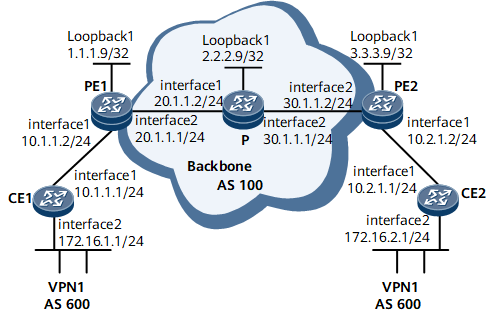
Networking Requirements
On the network shown in Figure 1, CE1 and CE2 belong to the same VPN; CE1 connects to PE1; CE2 connects to PE2; CE1 and CE2 both use AS600. When EBGP runs between a PE and a CE, the BGP routes sent from the CE to the PE carry the AS_Path attribute. The local PE sends the BGP routes to the remote PE through MP-IBGP. When the remote PE sends the BGP routes to its connected CE through EBGP, the CE discards the BGP routes whose AS_Path attribute carries AS600.
To address the preceding problem, it is required that AS number substitution be configured on the PEs. Then, when a PE sends VPN routes to a CE through BGP, it substitutes its own AS number (AS 100 in this example) for the AS numbers in the VPN routes. Then, the CE can receive the remote VPN routes.

Configuration Notes
Before configuring BGP AS number substitution, configure EBGP on the PEs and CEs.
Configuration Roadmap
The configuration roadmap is as follows:
Configure a basic BGP/MPLS IP VPN.
Configure BGP AS number substitution on the PEs.
Data Preparation
To complete the configuration, you need the following data:
MPLS LSR IDs of the PEs and P
VPN instances on PE1 and PE2
AS numbers of the CEs (CE1 and CE2 having the same AS number that is different from the AS number of the backbone network)
Procedure
- Configure a basic BGP/MPLS IP VPN.
The configurations include:
Configure OSPF on the MPLS backbone network so that the PEs and P can learn the routes to the loopback interfaces of each other.
Configure MPLS and MPLS LDP both globally and per interface on each node of the backbone network and set up LDP LSPs.
Set up MP-IBGP peer relationships between the PEs and advertise VPNv4 routes.
Configure an IPv4-address-family-supporting VPN instance on PE1 and bind the interface that connects PE1 to CE1 to the VPN instance on PE1.
Configure an IPv4-address-family-supporting VPN instance on PE2 and bind the interface that connects PE2 to CE2 to the VPN instance on PE2.
Configure EBGP on PE1, CE1, PE2, and CE2 and import the routes of each CE to its connected PE.
For configuration details, see Configuration Files in this section.
After completing the configurations, run the display ip routing-table command on CE2. The command output shows that CE2 has learned the route to the network segment (10.1.1.0/24) where the interface that connects CE1 to PE1 resides, but there is no route to the VPN (172.16.1.0/24) of CE1. The case is the same on CE1.
<CE2> display ip routing-table
Route Flags: R - relay, D - download to fib, T - to vpn-instance, B - black hole route
------------------------------------------------------------------------------
Routing Table: _public_
         Destinations : 12        Routes : 12
Destination/Mask    Proto  Pre  Cost     Flags  NextHop         Interface
     10.1.1.0/24    EBGP   255  0        D      10.2.1.2        GigabitEthernet0/1/0
     10.1.1.1/32    EBGP   255  0        D      10.2.1.2        GigabitEthernet0/1/0
     10.2.1.0/24    Direct 0    0        D      10.2.1.1        GigabitEthernet0/1/0
     10.2.1.1/32    Direct 0    0        D      127.0.0.1       GigabitEthernet0/1/0
   10.2.1.255/32    Direct 0    0        D      127.0.0.1       GigabitEthernet0/1/0
     127.0.0.0/8    Direct 0    0        D      127.0.0.1       InLoopBack0
    127.0.0.1/32    Direct 0    0        D      127.0.0.1       InLoopBack0
127.255.255.255/32  Direct 0    0        D      127.0.0.1       InLoopBack0
    172.16.2.0/24    Direct 0    0        D      172.16.2.1     GigabitEthernet0/1/8
    172.16.2.1/32    Direct 0    0        D      127.0.0.1      GigabitEthernet0/1/8
255.255.255.255/32  Direct 0    0        D      127.0.0.1       InLoopBack0
Run the display ip routing-table vpn-instance command on PEs. The command output shows that the VPN routing table has routes to the VPN of the CEs.
The following example uses the command output on PE2.
<PE2> display ip routing-table vpn-instance vpn1
Route Flags: R - relay, D - download to fib, T - to vpn-instance, B - black hole route
------------------------------------------------------------------------------
Routing Table: vpn1
         Destinations : 9        Routes : 9
Destination/Mask    Proto  Pre  Cost     Flags  NextHop         Interface
     10.1.1.0/24    IBGP   255  0        RD     1.1.1.9         GigabitEthernet0/1/8
     10.1.1.1/32    IBGP   255  0        RD     1.1.1.9         GigabitEthernet0/1/8
     10.1.1.2/32    IBGP   255  0        RD     1.1.1.9         GigabitEthernet0/1/8
     10.2.1.0/24    Direct 0    0        D      10.2.1.2        GigabitEthernet0/1/0
     10.2.1.2/32    Direct 0    0        D      127.0.0.1       GigabitEthernet0/1/0
   10.2.1.255/32    Direct 0    0        D      127.0.0.1       GigabitEthernet0/1/0
    172.16.1.0/24  IBGP   255  0       RD     1.1.1.9         GigabitEthernet0/1/8
    172.16.2.0/24   EBGP   255  0        D      10.2.1.1        GigabitEthernet0/1/0
255.255.255.255/32  Direct 0    0        D      127.0.0.1       InLoopBack0
Run the display bgp routing-table peer received-routes command on CE2. The command output shows that CE2 receives no route to 172.16.1.0/24.
<CE2> display bgp routing-table peer 10.2.1.2 received-routes
 BGP Local router ID is 10.2.1.1
 Status codes: * - valid, > - best, d - damped, x - best external, a - add path,
               h - history,  i - internal, s - suppressed, S - Stale
               Origin : i - IGP, e - EGP, ? - incomplete
 RPKI validation codes: V - valid, I - invalid, N - not-found
 Total Number of Routes: 4
      Network          NextHop        MED     LocPrf    PrefVal Path/Ogn
 *>   10.1.1.0/24      10.2.1.2                           0      100?
 *>   10.1.1.1/32      10.2.1.2                           0      100?
 *    10.2.1.0/24      10.2.1.2        0                  0      100?
 *>   10.2.1.1/32      10.2.1.2        0                  0      100?
- Configure BGP AS number substitution.
Configure BGP AS number substitution on the PEs.
# Use PE2 as an example:
[~PE2] bgp 100
[*PE2-bgp] ipv4-family vpn-instance vpn1
[*PE2-bgp-vpn1] peer 10.2.1.1 substitute-as
[*PE2-bgp-vpn1] commit
Check the routing information received by CE2 and routing table information of CE2.
<CE2> display bgp routing-table peer 10.2.1.2 received-routes
 BGP Local router ID is 10.2.1.1
 Status codes: * - valid, > - best, d - damped, x - best external, a - add path,
               h - history,  i - internal, s - suppressed, S - Stale
               Origin : i - IGP, e - EGP, ? - incomplete
 RPKI validation codes: V - valid, I - invalid, N - not-found
 Total Number of Routes: 6
      Network          NextHop       MED      LocPrf    PrefVal Path/Ogn
 *>   10.1.1.0/24      10.2.1.2                           0      100?
 *>   10.1.1.1/32      10.2.1.2                           0      100?
 *>   10.1.1.2/32      10.2.1.2                           0      100 100?
 *    10.2.1.0/24      10.2.1.2       0                   0      100?
 *    10.2.1.1/32      10.2.1.2       0                   0      100?
 *>   172.16.1.0/24    10.2.1.2                           0      100 100?
<CE2> display ip routing-table
Route Flags: R - relay, D - download to fib, T - to vpn-instance, B - black hole route
------------------------------------------------------------------------------
Routing Table: _public_
         Destinations : 13        Routes : 13
Destination/Mask    Proto  Pre  Cost       Flags  NextHop         Interface
     10.1.1.0/24    EBGP   255  0          D      10.2.1.2        GigabitEthernet0/1/0
     10.1.1.1/32    EBGP   255  0          D      10.2.1.2        GigabitEthernet0/1/0
     10.2.1.0/24    Direct 0    0          D      10.2.1.1        GigabitEthernet0/1/0
     10.2.1.1/32    Direct 0    0          D      127.0.0.1       GigabitEthernet0/1/0
   10.2.1.255/32    Direct 0    0          D      127.0.0.1       GigabitEthernet0/1/0
    172.16.1.1/24 EBGP   255  0          D      10.2.1.2        GigabitEthernet0/1/0
    127.0.0.0/8     Direct 0    0          D      127.0.0.1       InLoopBack0
    127.0.0.1/32    Direct 0    0          D      127.0.0.1       InLoopBack0
127.255.255.255/32  Direct 0    0          D      127.0.0.1       InLoopBack0
    172.16.2.0/24   Direct 0    0          D      127.0.0.1       GigabitEthernet0/1/8
    172.16.2.1/32   Direct 0    0          D      127.0.0.1       GigabitEthernet0/1/8
255.255.255.255/32  Direct 0    0          D      127.0.0.1       InLoopBack0
After configuring BGP AS number substitution on PE1, you can find that CE1 and CE2 can ping each other through GE interfaces.
[*CE1] ping -a 172.16.1.1 172.16.2.1
  PING 172.16.2.1: 56  data bytes, press CTRL_C to break
    Reply from 172.16.2.1: bytes=56 Sequence=1 ttl=253 time=109 ms
    Reply from 172.16.2.1: bytes=56 Sequence=2 ttl=253 time=67 ms
    Reply from 172.16.2.1: bytes=56 Sequence=3 ttl=253 time=66 ms
    Reply from 172.16.2.1: bytes=56 Sequence=4 ttl=253 time=85 ms
    Reply from 172.16.2.1: bytes=56 Sequence=5 ttl=253 time=70 ms
  --- 172.16.2.1 ping statistics ---
    5 packet(s) transmitted
    5 packet(s) received
    0.00% packet loss
    round-trip min/avg/max = 66/79/109 ms
Configuration Files
CE1 configuration file
#
 sysname CE1
#
interface GigabitEthernet0/1/0
 undo shutdown
 ip address 10.1.1.1 255.255.255.0
#
interface GigabitEthernet0/1/8
 undo shutdown
 ip address 172.16.1.1 255.255.255.0
#
bgp 600
 peer 10.1.1.2 as-number 100
 #
 ipv4-family unicast
  undo synchronization
  import-route direct
  peer 10.1.1.2 enable
#
return
PE1 configuration file
#
 sysname PE1
#
ip vpn-instance vpn1
 ipv4-family
  route-distinguisher 100:1
  apply-label per-instance
  vpn-target 1:1 export-extcommunity
  vpn-target 1:1 import-extcommunity
#
mpls lsr-id 1.1.1.9
#
mpls
#
mpls ldp
#
interface GigabitEthernet0/1/0
 undo shutdown
 ip binding vpn-instance vpn1
 ip address 10.1.1.2 255.255.255.0
#
interface GigabitEthernet0/1/8
 undo shutdown
 ip address 20.1.1.1 255.255.255.0
 mpls
 mpls ldp
#
interface LoopBack1
 ip address 1.1.1.9 255.255.255.255
#
bgp 100
 peer 3.3.3.9 as-number 100
 peer 3.3.3.9 connect-interface LoopBack1
 #
 ipv4-family unicast
  undo synchronization
  peer 3.3.3.9 enable
 #
 ipv4-family vpnv4
  policy vpn-target
  peer 3.3.3.9 enable
#
 ipv4-family vpn-instance vpn1
  peer 10.1.1.1 as-number 600
  peer 10.1.1.1 substitute-as
  import-route direct
#
ospf 1
 area 0.0.0.0
  network 1.1.1.9 0.0.0.0
  network 20.1.1.0 0.0.0.255
#
return
P configuration file
#
 sysname P
#
mpls lsr-id 2.2.2.9
#
mpls
#
mpls ldp
#
interface GigabitEthernet0/1/0
 undo shutdown
 ip address 20.1.1.2 255.255.255.0
 mpls
 mpls ldp
#
interface GigabitEthernet0/1/8
 undo shutdown
 ip address 30.1.1.1 255.255.255.0
 mpls
 mpls ldp
#
interface LoopBack1
 ip address 2.2.2.9 255.255.255.255
#
ospf 1
 area 0.0.0.0
  network 2.2.2.9 0.0.0.0
  network 20.1.1.0 0.0.0.255
  network 30.1.1.0 0.0.0.255
#
return
PE2 configuration file
#
 sysname PE2
#
ip vpn-instance vpn1
 ipv4-family
  route-distinguisher 100:1
  apply-label per-instance
  vpn-target 1:1 export-extcommunity
  vpn-target 1:1 import-extcommunity
#
mpls lsr-id 3.3.3.9
#
mpls
#
mpls ldp
#
interface GigabitEthernet0/1/0
 undo shutdown
 ip binding vpn-instance vpn1
 ip address 10.2.1.2 255.255.255.0
#
interface GigabitEthernet0/1/8
 undo shutdown
 ip address 30.1.1.2 255.255.255.0
 mpls
 mpls ldp
#
interface LoopBack1
 ip address 3.3.3.9 255.255.255.255
#
bgp 100
 peer 1.1.1.9 as-number 100
 peer 1.1.1.9 connect-interface LoopBack1
 #
 ipv4-family unicast
  undo synchronization
  peer 1.1.1.9 enable
 #
 ipv4-family vpnv4
  policy vpn-target
  peer 1.1.1.9 enable
#
 ipv4-family vpn-instance vpn1
  peer 10.2.1.1 as-number 600
  peer 10.2.1.1 substitute-as
  import-route direct
#
ospf 1
 area 0.0.0.0
  network 3.3.3.9 0.0.0.0
  network 30.1.1.0 0.0.0.255
#
return
CE2 configuration file
#
 sysname CE2
#
interface GigabitEthernet0/1/0
 undo shutdown
 ip address 10.2.1.1 255.255.255.0
#
interface GigabitEthernet0/1/8
 undo shutdown
 ip address 172.16.2.1 255.255.255.0
#
bgp 600
 peer 10.2.1.2 as-number 100
 #
 ipv4-family unicast
  undo synchronization
  import-route direct
  peer 10.2.1.2 enable
#
return