Example for Configuring Extranet VPN
Configuring extranet VPN enables users in a VPN to access sites in other VPNs.
Networking Requirements
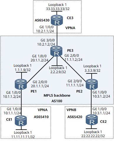
On the network shown in Figure 1, CE1 and CE3 belong to VPNA; CE2 belongs to VPNB. By default, devices in different VPNs cannot communicate with each other. In some scenarios, however, devices in different VPNs need to communicate with each other. In this case, you can configure VPN targets for the communication between CE2 and CE3.

Configuration Notes
When configuring extranet VPN, note the following:
The import VPN target list of PE3 contains the export VPN targets of PE1 and PE2; the export VPN target list of PE3 contains the import VPN targets of PE1 and PE2.
Configuration Roadmap
The configuration roadmap is as follows:
Configure an IGP on the MPLS backbone network to enable PEs to communicate.
Configure MPLS and MPLS LSPs on the MPLS backbone network so that PEs can communicate over the LSPs.
Establish an MP-IBGP peer relationship between PE1 and PE3, and between PE2 and PE3.
Configure VPN instances on PEs, ensuring that the import VPN target list of PE3 contains the export VPN targets of the other PEs and the export VPN target list of PE3 contains the import VPN targets of the other PEs
Data Preparation
To complete the configuration, you need the following data:
MPLS LSR IDs of PEs
Names, RDs, and VPN targets of the VPN instances created on PE1 and PE2
AS numbers of PEs and CEs
Procedure
- Configure an IGP on the MPLS backbone network so that the PEs can learn the routes to each other's loopback interface. This example uses OSPF as the IGP. For configuration details, see Configuration Files in this section.
After the configurations are complete, the OSPF neighbor relationships can be established between PEs. Run the display ospf peer command. The command output shows that the neighbor relationship is in the Full state. Run the display ip routing-table command. The command output shows that PEs have learned the routes to each other's loopback interface.
- Set up LDP LSPs on the MPLS backbone network.
# Configure PE1.
[~PE1] mpls lsr-id 1.1.1.9
[*PE1] mpls
[*PE1-mpls] quit
[*PE1] mpls ldp
[*PE1-mpls-ldp] quit
[*PE1] interface gigabitethernet 0/1/8
[*PE1-GigabitEthernet0/1/8] mpls
[*PE1-GigabitEthernet0/1/8] mpls ldp
[*PE1-GigabitEthernet0/1/8] commit
[~PE1-GigabitEthernet0/1/8] quit
# Configure PE2.
[~PE2] mpls lsr-id 3.3.3.9
[*PE2] mpls
[*PE2-mpls] quit
[*PE2] mpls ldp
[*PE2-mpls-ldp] quit
[*PE2] interface gigabitethernet 0/1/8
[*PE2-GigabitEthernet0/1/8] mpls
[*PE2-GigabitEthernet0/1/8] mpls ldp
[*PE2-GigabitEthernet0/1/8] commit
[~PE2-GigabitEthernet0/1/8] quit
# Configure PE3.
[~PE3] mpls lsr-id 2.2.2.9
[*PE3] mpls
[*PE3-mpls] quit
[*PE3] mpls ldp
[*PE3-mpls-ldp] quit
[*PE3] interface gigabitethernet 0/1/0
[*PE3-GigabitEthernet0/1/0] mpls
[*PE3-GigabitEthernet0/1/0] mpls ldp
[*PE3-GigabitEthernet0/1/0] commit
[*PE3-GigabitEthernet0/1/0] quit
[*PE3] interface gigabitethernet 0/1/8
[*PE3-GigabitEthernet0/1/8] mpls
[*PE3-GigabitEthernet0/1/8] mpls ldp
[*PE3-GigabitEthernet0/1/8] commit
[~PE3-GigabitEthernet0/1/8] quit
After the configurations are complete, the LDP sessions can be established between PEs. Run the display mpls ldp session command on each device. The command output shows that the Status field is Operational. The following example uses the command output on PE1.
<PE1> display mpls ldp session LDP Session(s) in Public Network Codes: LAM(Label Advertisement Mode), SsnAge Unit(DDDD:HH:MM) An asterisk (*) before a session means the session is being deleted. ------------------------------------------------------------------------- PeerID Status LAM SsnRole SsnAge KASent/Rcv ------------------------------------------------------------------------- 2.2.2.9:0 Operational DU Passive 0000:00:01 5/5 3.3.3.9:0 Operational DU Passive 0000:00:01 5/5 ------------------------------------------------------------------------- TOTAL: 2 session(s) Found. - Establish an MP-IBGP peer relationship between PE1 and PE3, and between PE2 and PE3.
# Configure PE1.
[~PE1] bgp 100
[*PE1-bgp] peer 2.2.2.9 as-number 100
[*PE1-bgp] peer 2.2.2.9 connect-interface loopback 1
[*PE1-bgp] ipv4-family vpnv4
[*PE1-bgp-af-vpnv4] peer 2.2.2.9 enable
[*PE1-bgp-af-vpnv4] commit
[~PE1-bgp-af-vpnv4] quit
[~PE1-bgp] quit
# Configure PE2.
[~PE2] bgp 100
[*PE2-bgp] peer 2.2.2.9 as-number 100
[*PE2-bgp] peer 2.2.2.9 connect-interface loopback 1
[*PE2-bgp] ipv4-family vpnv4
[*PE2-bgp-af-vpnv4] peer 2.2.2.9 enable
[*PE2-bgp-af-vpnv4] commit
[~PE2-bgp-af-vpnv4] quit
[~PE2-bgp] quit
# Configure PE3.
[~PE3] bgp 100
[*PE3-bgp] peer 1.1.1.9 as-number 100
[*PE3-bgp] peer 3.3.3.9 connect-interface loopback 1
[*PE3-bgp] ipv4-family vpnv4
[*PE3-bgp-af-vpnv4] peer 1.1.1.9 enable
[*PE3-bgp-af-vpnv4] peer 3.3.3.9 enable
[*PE3-bgp-af-vpnv4] commit
[~PE3-bgp-af-vpnv4] quit
[~PE3-bgp] quit
After completing the configurations, run the display bgp vpnv4 all peer command on PEs. The command output shows that MP-IBGP peer relationships have been established between PEs and CEs. The following example uses the command output on PE1.
<PE1> display bgp vpnv4 all peer
BGP local router ID : 1.1.1.9
 Local AS number : 100
 Total number of peers : 1                 Peers in established state : 3
  Peer            V    AS  MsgRcvd  MsgSent    OutQ  Up/Down    State        PrefRcv
  2.2.2.9         4   100   12      18         0     00:09:38   Established   0
- Configure VPN instances on PEs, ensuring that the import VPN target list of PE3 contains the export VPN targets of the other PEs and the export VPN target list of PE3 contains the import VPN targets of the other PEs
# Configure PE1.
[~PE1] ip vpn-instance vpna
[*PE1-vpn-instance-vpna] ipv4-family
[*PE1-vpn-instance-vpna-af-ipv4] route-distinguisher 100:1
[*PE1-vpn-instance-vpna-af-ipv4] vpn-target 111:1 both
[*PE1-vpn-instance-vpna-af-ipv4] commit
[*PE1-vpn-instance-vpna-af-ipv4] quit
[*PE1-vpn-instance-vpna] quit
[*PE1] interface gigabitethernet 0/1/0
[*PE1-GigabitEthernet0/1/0] ip binding vpn-instance vpna
[*PE1-GigabitEthernet0/1/0] ip address 10.1.1.2 24
[*PE1-GigabitEthernet0/1/0] commit
[~PE1-GigabitEthernet0/1/0] quit
# Configure PE2.
[~PE2] ip vpn-instance vpnb
[*PE2-vpn-instance-vpnb] ipv4-family
[*PE2-vpn-instance-vpnb-af-ipv4] route-distinguisher 100:2
[*PE2-vpn-instance-vpnb-af-ipv4] vpn-target 222:2 both
[*PE2-vpn-instance-vpnb-af-ipv4] commit
[*PE2-vpn-instance-vpnb-af-ipv4] quit
[*PE2-vpn-instance-vpnb] quit
[*PE2] interface gigabitethernet 0/1/0
[*PE2-GigabitEthernet0/1/0] ip binding vpn-instance vpnb
[*PE2-GigabitEthernet0/1/0] ip address 10.3.1.2 24
[*PE2-GigabitEthernet0/1/0] commit
[~PE2-GigabitEthernet0/1/0] quit
# Configure PE3.
[~PE3] ip vpn-instance vpna
[*PE3-vpn-instance-vpna] ipv4-family
[*PE3-vpn-instance-vpna-af-ipv4] route-distinguisher 100:3
[*PE3-vpn-instance-vpna-af-ipv4] vpn-target 111:1 222:2 both
[*PE3-vpn-instance-vpna-af-ipv4] commit
[*PE3-vpn-instance-vpna-af-ipv4] quit
[*PE3-vpn-instance-vpna] quit
[*PE3] interface gigabitethernet 0/1/16
[*PE3-GigabitEthernet0/1/16] ip binding vpn-instance vpna
[*PE3-GigabitEthernet0/1/16] ip address 10.2.1.2 24
[*PE3-GigabitEthernet0/1/16] commit
[~PE3-GigabitEthernet0/1/16] quit
- Set up EBGP peer relationships between PEs and CEs to import VPN routes.
# Configure CE1.
[~CE1] interface loopback 1
[*CE1-Loopback1] ip address 11.11.11.11 32
[*CE1-Loopback1] quit
[*CE1] bgp 65410
[*CE1-bgp] peer 10.1.1.2 as-number 100
[*CE1-bgp] network 11.11.11.11 32
[*CE1-bgp] commit
The configurations of CE2 and CE3 are similar to the configuration of CE1. For configuration details, see Configuration Files in this section.
# Configure PE1.
[~PE1] bgp 100
[~PE1-bgp] ipv4-family vpn-instance vpna
[*PE1-bgp-vpna] peer 10.1.1.1 as-number 65410
[*PE1-bgp-vpna] commit
[~PE1-bgp-vpna] quit
The configurations of PE2 and PE3 are similar to the configuration of PE1. For configuration details, see Configuration Files in this section.
After completing the configurations, run the display bgp vpnv4 vpn-instance peer command on PEs. The command output shows that BGP peer relationships have been established between PEs and CEs.
The following example uses the peer relationship between PE1 and CE1.
<PE1> display bgp vpnv4 vpn-instance vpna peer
 BGP local router ID : 1.1.1.9
 Local AS number : 100
 Total number of peers : 1            Peers in established state : 1
  Peer            V    AS  MsgRcvd  MsgSent    OutQ  Up/Down    State        PrefRcv
  10.1.1.1        4   65410  11     9          0     00:06:37   Established  1
- Verify the configuration.
Run the display ip routing-table command on CE1. The command output shows routes to CE3, not CE2.
<CE1> display ip routing-table
Route Flags: R - relay, D - download to fib, T - to vpn-instance, B - black hole route
------------------------------------------------------------------------------
Routing Table: _public_
         Destinations : 7        Routes : 7
Destination/Mask    Proto  Pre  Cost     Flags NextHop         Interface
   11.11.11.11/32    Direct 0    0        D     127.0.0.1       Loopback1
     10.1.1.0/24     Direct 0    0        D     127.0.0.1       GigabitEthernet0/1/0
     10.1.1.1/32     Direct 0    0        D     127.0.0.1       GigabitEthernet0/1/0
   10.1.1.255/32     Direct 0    0        D     127.0.0.1       GigabitEthernet0/1/0
  33.33.33.33/32    EBGP   255  0        RD    2.2.2.9         GigabitEthernet0/1/8
127.255.255.255/32   Direct 0    0        D     127.0.0.1       InLoopBack0
255.255.255.255/32   Direct 0    0        D     127.0.0.1       InLoopBack0
CE2 can successfully ping CE3 at 33.33.33.33 but cannot successfully ping CE1 at 22.22.22.22.
[*CE1] ping -a 11.11.11.11 33.33.33.33
  PING 33.33.33.33: 56  data bytes, press CTRL_C to break
    Reply from 33.33.33.33: bytes=56 Sequence=1 ttl=253 time=72 ms
    Reply from 33.33.33.33: bytes=56 Sequence=2 ttl=253 time=34 ms
    Reply from 33.33.33.33: bytes=56 Sequence=3 ttl=253 time=50 ms
    Reply from 33.33.33.33: bytes=56 Sequence=4 ttl=253 time=50 ms
    Reply from 33.33.33.33: bytes=56 Sequence=5 ttl=253 time=34 ms
  --- 33.33.33.33 ping statistics ---
    5 packet(s) transmitted
    5 packet(s) received
    0.00% packet loss
    round-trip min/avg/max = 34/48/72 ms
[*CE1] ping -a 11.11.11.11 22.22.22.22
  PING 22.22.22.22: 56  data bytes, press CTRL_C to break
    Request time out
    Request time out
    Request time out
    Request time out
    Request time out
  --- 22.22.22.22 ping statistics ---
    5 packet(s) transmitted
    0 packet(s) received
    100.00% packet loss
Configuration Files
CE1 configuration file
#
 sysname CE1
#
interface GigabitEthernet0/1/0
 undo shutdown
 ip address 10.1.1.1 255.255.255.0
#
interface Loopback 1
 undo shutdown
 ip address 11.11.11.11 255.255.255.255
#
bgp 65410
 peer 10.1.1.2 as-number 100
 #
 ipv4-family unicast
  undo synchronization
  peer 10.1.1.2 enable
  network 11.11.11.11 255.255.255.255
#
return
PE1 configuration file
#
 sysname PE1
#
ip vpn-instance vpna
 ipv4-family
  route-distinguisher 100:1
  apply-label per-instance
  vpn-target 111:1 export-extcommunity
  vpn-target 111:1 import-extcommunity
#
mpls lsr-id 1.1.1.9
#
mpls
#
mpls ldp
#
interface GigabitEthernet0/1/0
 undo shutdown
 ip binding vpn-instance vpna
 ip address 10.1.1.2 255.255.255.0
#
interface GigabitEthernet0/1/8
 undo shutdown
 ip address 20.1.1.1 255.255.255.0
 mpls
 mpls ldp
#
interface LoopBack1
 ip address 1.1.1.9 255.255.255.255
#
bgp 100
 peer 2.2.2.9 as-number 100
 peer 2.2.2.9 connect-interface LoopBack1
 #
 ipv4-family unicast
  undo synchronization
  peer 2.2.2.9 enable
 #
 ipv4-family vpnv4
  policy vpn-target
  peer 2.2.2.9 enable
#
 ipv4-family vpn-instance vpna
  peer 10.1.1.1 as-number 65410
#
ospf 1
 area 0.0.0.0
  network 20.1.1.0 0.0.0.255
  network 1.1.1.9 0.0.0.0
#
return
PE2 configuration file
#
 sysname PE2
#
ip vpn-instance vpnb
 ipv4-family
  route-distinguisher 100:2
  apply-label per-instance
  vpn-target 222:2 export-extcommunity
  vpn-target 222:2 import-extcommunity
#
mpls lsr-id 3.3.3.9
#
mpls
#
mpls ldp
#
interface GigabitEthernet0/1/0
 undo shutdown
 ip binding vpn-instance vpnb
 ip address 10.3.1.2 255.255.255.0
#
interface GigabitEthernet0/1/8
 undo shutdown
 ip address 11.1.1.1 255.255.255.0
 mpls
 mpls ldp
#
interface LoopBack1
 ip address 3.3.3.9 255.255.255.255
#
bgp 100
 peer 2.2.2.9 as-number 100
 peer 2.2.2.9 connect-interface LoopBack1
 #
 ipv4-family unicast
  undo synchronization
  peer 2.2.2.9 enable
 #
 ipv4-family vpnv4
  policy vpn-target
  peer 2.2.2.9 enable
#
 ipv4-family vpn-instance vpnb
  peer 10.3.1.1 as-number 65420
#
ospf 1
 area 0.0.0.0
  network 3.3.3.9 0.0.0.0
  network 11.1.1.0 0.0.0.255
#
return
CE2 configuration file
#
 sysname CE2
#
interface GigabitEthernet0/1/0
 undo shutdown
 ip address 10.3.1.1 255.255.255.0
#
interface Loopback 1
 undo shutdown
 ip address 22.22.22.22 255.255.255.255
#
bgp 65420
 peer 10.3.1.2 as-number 100
 #
 ipv4-family unicast
  undo synchronization
  peer 10.3.1.2 enable
  network 22.22.22.22 255.255.255.255
#
return
PE3 configuration file
#
 sysname PE3
#
ip vpn-instance vpna
 ipv4-family
  route-distinguisher 100:3
  apply-label per-instance
  vpn-target 111:1 222:2 import-extcommunity
  vpn-target 111:1 222:2 export-extcommunity
#
mpls lsr-id 2.2.2.9
#
mpls
#
mpls ldp
#
interface GigabitEthernet0/1/0
 undo shutdown
 ip address 20.1.1.2 255.255.255.0
 mpls
 mpls ldp
#
interface GigabitEthernet0/1/8
 undo shutdown
 ip address 11.1.1.2 255.255.255.0
 mpls
 mpls ldp
#
interface GigabitEthernet0/1/16
 undo shutdown
 ip binding vpn-instance vpna
 ip address 10.2.1.2 255.255.255.0
#
interface LoopBack1
 ip address 2.2.2.9 255.255.255.255
#
bgp 100
 peer 1.1.1.9 as-number 100
 peer 1.1.1.9 connect-interface LoopBack1
 peer 3.3.3.9 as-number 100
 peer 3.3.3.9 connect-interface LoopBack1
 #
 ipv4-family unicast
  undo synchronization
  peer 1.1.1.9 enable
  peer 3.3.3.9 enable
 #
 ipv4-family vpnv4
  policy vpn-target
  peer 1.1.1.9 enable
  peer 3.3.3.9 enable
#
 ipv4-family vpn-instance vpna
  peer 10.2.1.1 as-number 65430
#
ospf 1
 area 0.0.0.0
  network 2.2.2.9 0.0.0.0
  network 20.1.1.0 0.0.0.255
  network 11.1.1.0 0.0.0.255
#
return
CE3 configuration file
#
 sysname CE3
#
interface GigabitEthernet0/1/0
 undo shutdown
 ip address 10.2.1.1 255.255.255.0
#
interface Loopback 1
 undo shutdown
 ip address 33.33.33.33 255.255.255.255
#
bgp 65430
 peer 10.2.1.2 as-number 100
 network 33.33.33.33 255.255.255.255
 #
 ipv4-family unicast
  undo synchronization
  peer 10.2.1.2 enable
#
return