Example for Configuring Inter-AS VPN Option B with an RR in an AS
A single-hop MP-EBGP peer relationship can be established between the ASBRs to implement inter-AS VPN Option B, and an RR can be configured in an AS to reflect VPNv4 routes.
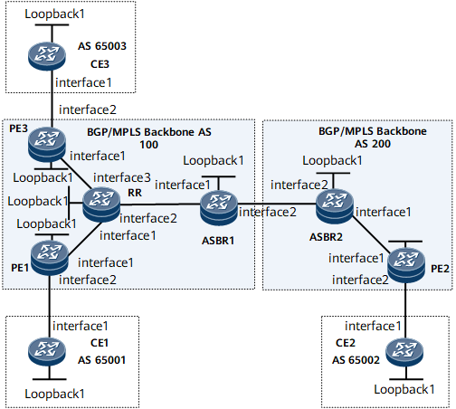
Networking Requirements
On the network shown in Figure 1, CE1, CE2, and CE3 belong to the same VPN; PE1 and PE3 are in the same AS. It is required that inter-AS VPN Option B be configured and an RR be configured in AS100 to reflect VPNv4 routes between PEs and between a PE and an ASBR so as to reduce MP-IBGP connections in AS100.

Interfaces 1 through 3 in this example represent GE 0/1/0, GE 0/1/8, and GE 0/1/16, respectively.
Device Name |
Interface |
IP Address |
|---|---|---|
CE1 |
Loopback 1 |
11.11.11.11/32 |
GE 0/1/0 |
10.1.1.1/24 |
|
PE1 |
Loopback 1 |
1.1.1.1/32 |
GE 0/1/8 |
10.1.1.2/24 |
|
GE 0/1/0 |
10.10.1.2/24 |
|
RR |
Loopback 1 |
4.4.4.4/32 |
GE 0/1/0 |
10.10.1.1/24 |
|
GE 0/1/8 |
10.20.1.1/24 |
|
GE 0/1/16 |
10.30.1.1/24 |
|
CE3 |
Loopback 1 |
33.33.33.33/32 |
GE 0/1/0 |
10.3.1.1/24 |
|
PE3 |
Loopback 1 |
3.3.3.3/32 |
GE 0/1/0 |
10.3.1.2/24 |
|
GE 0/1/8 |
10.30.1.2/24 |
|
ASBR1 |
Loopback 1 |
5.5.5.5/32 |
GE 0/1/0 |
10.20.1.2/24 |
|
GE 0/1/8 |
12.12.12.1/24 |
|
ASBR2 |
Loopback 1 |
6.6.6.6/32 |
GE 0/1/0 |
10.40.1.1/24 |
|
GE 0/1/8 |
12.12.12.2/24 |
|
CE2 |
Loopback 1 |
22.22.22.22/32 |
GE 0/1/0 |
10.2.1.1/24 |
|
PE2 |
Loopback 1 |
2.2.2.2/32 |
GE 0/1/0 |
10.2.1.2/24 |
|
GE 0/1/8 |
10.40.1.2/24 |
Configuration Notes
When configuring inter-AS VPN Option B with an RR in a AS, note the following:
There is no need to create VPN instances on ASBRs or configure ASBRs to filter VPNv4 routes based on VPN targets.
PE1, PE3, and ASBR1 must be configured as clients for the RR.
Configuration Roadmap
The configuration roadmap is as follows:
Configure an IGP on the MPLS backbone network for IP connectivity between the ASBR and PE in the same AS, and set up an MPLS LDP LSP between the ASBR and PE in the same AS.
Set up EBGP peer relationships between PEs and CEs and set up MP-IBGP peer relationships between the PEs and ASBRs in the same AS.
Enable route reflection for VPNv4 routes on the RR.
Configure VPN instances on PEs, but not on ASBRs or the RR.
Enable MPLS on the interface connected to ASBRs. Set up the MP-EBGP peer relationship between ASBRs. Configure no VPN-Target filtration on the received VPNv4 routes.
Data Preparation
To complete the configuration, you need the following data:
AS numbers of PEs and CEs
MPLS LSR IDs of the PEs and the ASBRs
Names, RDs, and VPN targets of the VPN instances created on PE1 and PE2
Procedure
- On the MPLS backbone networks in AS100 and AS200, configure an IGP to interconnect the devices in the same AS. This example uses OSPF as the IGP. For configuration details, see Configuration Files in this section.
After the configurations are complete, the OSPF neighbor relationship can be established between the devices in the same AS. Run the display ospf peer command. The command output shows that the neighbor relationship is in the Full state. Run the display ip routing-table command. The command output shows that the PEs have learned the routes to each other's loopback interface.
- Configure MPLS and MPLS LDP both globally and per interface on each node of the MPLS backbone networks in AS100 and AS200 and set up LDP LSPs.
# Configure PE1.
[~PE1] mpls lsr-id 1.1.1.1
[*PE1] mpls
[*PE1-mpls] quit
[*PE1] mpls ldp
[*PE1-mpls-ldp] quit
[*PE1] interface gigabitethernet 0/1/0
[*PE1-GigabitEthernet0/1/0] mpls
[*PE1-GigabitEthernet0/1/0] mpls ldp
[*PE1-GigabitEthernet0/1/0] commit
[~PE1-GigabitEthernet0/1/0] quit
The configurations of PE2 and PE3 are similar to the configuration of PE1. For configuration details, see Configuration Files in this section.
# Configure the RR.
[~RR] mpls lsr-id 4.4.4.4
[*RR] mpls
[*RR-mpls] quit
[*RR] mpls ldp
[*RR-mpls-ldp] quit
[*RR] interface gigabitethernet 0/1/0
[*RR-GigabitEthernet0/1/0] mpls
[*RR-GigabitEthernet0/1/0] mpls ldp
[*RR-GigabitEthernet0/1/0] quit
[*RR] interface gigabitethernet 0/1/8
[*RR-GigabitEthernet0/1/8] mpls
[*RR-GigabitEthernet0/1/8] mpls ldp
[*RR-GigabitEthernet0/1/8] quit
[*RR] interface gigabitethernet 0/1/16
[*RR-GigabitEthernet0/1/16] mpls
[*RR-GigabitEthernet0/1/16] mpls ldp
[*RR-GigabitEthernet0/1/16] quit
[*RR] commit
# Configure ASBR1.
[~ASBR1] mpls lsr-id 5.5.5.5
[*ASBR1] mpls
[*ASBR1-mpls] quit
[*ASBR1] mpls ldp
[*ASBR1-mpls-ldp] quit
[*ASBR1] interface gigabitethernet 0/1/0
[*ASBR1-GigabitEthernet0/1/0] mpls
[*ASBR1-GigabitEthernet0/1/0] mpls ldp
[*ASBR1-GigabitEthernet0/1/0] quit
[*ASBR1] commit
The configuration of ASBR2 is similar to the configuration of ASBR1. For configuration details, see Configuration Files in this section.
After the configurations are complete, LDP sessions can be set up between PEs and the RR and between ASBRs and the RR. Run the display mpls ldp session command on each device. The command output shows that the Status field is Operational. The following example uses the command output on PE1.
<PE1> display mpls ldp session LDP Session(s) in Public Network Codes: LAM(Label Advertisement Mode), SsnAge Unit(DDDD:HH:MM) An asterisk (*) before a session means the session is being deleted. ------------------------------------------------------------------------- PeerID Status LAM SsnRole SsnAge KASent/Rcv ------------------------------------------------------------------------- 4.4.4.4:0 Operational DU Passive 0000:00:01 5/5 ------------------------------------------------------------------------- TOTAL: 1 session(s) Found. - Set up MP-IBGP peer relationships between the PEs, ASBRs, and RR in AS100; set up an MP-IBGP peer relationship between the PE and ASBR in AS200.
# Configure PE1.
[~PE1] bgp 100
[*PE1-bgp] peer 4.4.4.4 as-number 100
[*PE1-bgp] peer 4.4.4.4 connect-interface loopback 1
[*PE1-bgp] ipv4-family vpnv4
[*PE1-bgp-af-vpnv4] peer 4.4.4.4 enable
[*PE1-bgp-af-vpnv4] commit
[~PE1-bgp-af-vpnv4] quit
[~PE1-bgp] quit
The configurations of PE2 and PE3 are similar to the configuration of PE1. For configuration details, see Configuration Files in this section.
# Configure ASBR1.
[~ASBR1] bgp 100
[*ASBR1-bgp] peer 4.4.4.4 as-number 100
[*ASBR1-bgp] peer 4.4.4.4 connect-interface loopback 1
[*ASBR1-bgp] ipv4-family vpnv4
[*ASBR1-bgp-af-vpnv4] peer 4.4.4.4 enable
[*ASBR1-bgp-af-vpnv4] commit
[~ASBR1-bgp-af-vpnv4] quit
[~ASBR1-bgp] quit
The configuration of ASBR2 is similar to the configuration of ASBR1. For configuration details, see Configuration Files in this section.
Set up MP-IBGP peer relationships between the RR and PE1, PE3, and ASBR1.
[~RR] bgp 100
[*RR-bgp] peer 1.1.1.1 as-number 100
[*RR-bgp] peer 1.1.1.1 connect-interface loopback 1
[*RR-bgp] peer 3.3.3.3 as-number 100
[*RR-bgp] peer 3.3.3.3 connect-interface loopback 1
[*RR-bgp] peer 5.5.5.5 as-number 100
[*RR-bgp] peer 5.5.5.5 connect-interface loopback 1
[*RR-bgp] ipv4-family vpnv4
[*RR-bgp-af-vpnv4] peer 1.1.1.1 enable
[*RR-bgp-af-vpnv4] peer 3.3.3.3 enable
[*RR-bgp-af-vpnv4] peer 5.5.5.5 enable
[*RR-bgp-af-vpnv4] commit
[~RR-bgp-af-vpnv4] quit
[~RR-bgp] quit
After completing the configurations, run the display bgp peer or display bgp vpnv4 all peer command on the PEs, RR, or ASBRs. The command output shows that the BGP peer relationships have been established between the PEs or ASBRs and the RR in AS100. The following example uses the command output on the RR.
<RR> display bgp vpnv4 all peer
BGP local router ID : 4.4.4.4
 Local AS number : 100
 Total number of peers : 3                 Peers in established state : 3
  Peer            V    AS  MsgRcvd  MsgSent    OutQ  Up/Down    State        PrefRcv
  1.1.1.1         4   100   12      18         0     00:09:38   Established   0
  3.3.3.3         4   100   12      18         0     00:09:38   Established   0
  5.5.5.5         4   100   12      18         0     00:09:38   Established   0
- Enable route reflection for VPNv4 routes on the RR.
# Configure the RR.
[~RR] bgp 100
[*RR-bgp] ipv4-family vpnv4
[*RR-bgp-af-vpnv4] undo policy vpn-target
[*RR-bgp-af-vpnv4] peer 1.1.1.1 reflect-client
[*RR-bgp-af-vpnv4] peer 3.3.3.3 reflect-client
[*RR-bgp-af-vpnv4] peer 5.5.5.5 reflect-client
[*RR-bgp-af-vpnv4] commit
[~RR-bgp-af-vpnv4] quit
[~RR-bgp] quit
- Configure a VPN instance on each PE and bind the interface that connects a PE to a CE to the VPN instance on that PE.
# Configure PE1.
[~PE1] ip vpn-instance vpna
[*PE1-vpn-instance-vpna] ipv4-family
[*PE1-vpn-instance-vpna-af-ipv4] route-distinguisher 100:1
[*PE1-vpn-instance-vpna-af-ipv4] vpn-target 111:1 both
[*PE1-vpn-instance-vpna-af-ipv4] quit
[*PE1-vpn-instance-vpna] quit
[*PE1] interface gigabitethernet 0/1/8
[*PE1-GigabitEthernet0/1/8] ip binding vpn-instance vpna
[*PE1-GigabitEthernet0/1/8] ip address 10.1.1.2 24
[*PE1-GigabitEthernet0/1/8] quit
[*PE1] commit
The configurations of PE2 and PE3 are similar to the configuration of PE1. For configuration details, see Configuration Files in this section.
# After completing the configurations, run the display ip vpn-instance verbose command on PEs. The command output shows the configurations of VPN instances.
<PE1> display ip vpn-instance verbose Total VPN-Instances configured : 1 Total IPv4 VPN-Instances configured : 1 Total IPv6 VPN-Instances configured : 0 VPN-Instance Name and ID : vpna, 1 Interfaces : GigabitEthernet0/1/8 Address family ipv4 Create date : 2009/09/18 11:30:35 Up time : 0 days, 00 hours, 05 minutes and 19 seconds Vrf Status : UP Route Distinguisher : 100:1 Export VPN Targets : 111:1 Import VPN Targets : 111:1 Label policy: label per route The diffserv-mode Information is : uniform The ttl-mode Information is : pipe - Set up EBGP peer relationships between PEs and CEs and import VPN routes to the loopback interfaces of the CEs.
# Configure CE1.
[~CE1] interface loopback 1
[*CE1-Loopback1] ip address 11.11.11.11 32
[*CE1-Loopback1] quit
[*CE1] bgp 65001
[*CE1-bgp] peer 10.1.1.2 as-number 100
[*CE1-bgp] network 11.11.11.11 32
[*CE1-bgp] quit
[*CE1] commit
The configurations of CE2 and CE3 are similar to the configuration of CE1. For configuration details, see Configuration Files in this section.
# Configure PE1.
[~PE1] bgp 100
[~PE1-bgp] ipv4-family vpn-instance vpna
[*PE1-bgp-vpna] peer 10.1.1.1 as-number 65001
[*PE1-bgp-vpna] commit
[~PE1-bgp-vpna] quit
The configurations of PE2 and PE3 are similar to the configuration of PE1. For configuration details, see Configuration Files in this section.
After completing the configurations, run the display bgp vpnv4 vpn-instance peer command on PEs. The command output shows that BGP peer relationships have been established between PEs and CEs.
The following example uses the peer relationship between PE1 and CE1.
<PE1> display bgp vpnv4 vpn-instance vpna peer
 BGP local router ID : 1.1.1.1
 Local AS number : 100
 Total number of peers : 1            Peers in established state : 1
  Peer            V    AS  MsgRcvd  MsgSent    OutQ  Up/Down    State        PrefRcv
  10.1.1.1        4   65001  11     9          0     00:06:37   Established  1
- Enable MPLS on the interface that connects one ASBR to the other ASBR, set up an MP-EBGP peer relationship between the ASBRs, and configure the ASBRs not to filter received VPNv4 routes based on VPN targets.# On ASBR 1, enable MPLS on GE 0/1/8 connected to ASBR 2.
[~ASBR1] interface GigabitEthernet 0/1/8
[~ASBR1-GigabitEthernet0/1/8] ip address 12.12.12.1 24
[*ASBR1-GigabitEthernet0/1/8] mpls
[*ASBR1-GigabitEthernet0/1/8] quit
[*ASBR1] commit
# On ASBR1, set up an MP-EBGP peer relationship between ASBR1 and ASBR2, and configure ASBR1 not to filter received VPNv4 routes based on VPN targets.
[~ASBR1] bgp 100
[~ASBR1-bgp] peer 12.12.12.2 as-number 200
[*ASBR1-bgp] ipv4-family vpnv4
[*ASBR1-bgp-af-vpnv4] peer 12.12.12.2 enable
[*ASBR1-bgp-af-vpnv4] undo policy vpn-target
[*ASBR1-bgp-af-vpnv4] commit
[~ASBR1-bgp-af-vpnv4] quit
[~ASBR1-bgp] quit
The configuration of ASBR2 is similar to the configuration of ASBR1. For configuration details, see Configuration Files in this section.
- Verify the configuration.
After the configurations are complete, CEs can learn routes to each other's loopback interface, and CE1 and CE2 can ping each other successfully.
The following example uses the command output on CE1.
<CE1> display ip routing-table
Route Flags: R - relay, D - download to fib, T - to vpn-instance, B - black hole route
------------------------------------------------------------------------------
Routing Table: _public_
         Destinations : 10        Routes : 10
Destination/Mask    Proto  Pre  Cost      Flags  NextHop         Interface
       10.1.1.0/24  Direct 0    0             D  10.1.1.1        GigabitEthernet0/1/0
       10.1.1.1/32  Direct 0    0             D  127.0.0.1       GigabitEthernet0/1/0
     10.1.1.255/32  Direct 0    0             D  127.0.0.1       GigabitEthernet0/1/0
    11.11.11.11/32  Direct 0    0             D  127.0.0.1       LoopBack1
   22.22.22.22/32  EBGP   255  0             D  10.1.1.2        GigabitEthernet0/1/0
   33.33.33.33/32  EBGP   255  0             D  10.1.1.2        GigabitEthernet0/1/0
      127.0.0.0/8   Direct 0    0             D  127.0.0.1       InLoopBack0
      127.0.0.1/32  Direct 0    0             D  127.0.0.1       InLoopBack0
127.255.255.255/32  Direct 0    0             D  127.0.0.1       InLoopBack0
255.255.255.255/32  Direct 0    0             D  127.0.0.1       InLoopBack0
<CE1> ping -a 11.11.11.11 22.22.22.22
  PING 22.22.22.22: 56  data bytes, press CTRL_C to break
    Reply from 22.22.22.22: bytes=56 Sequence=1 ttl=252 time=120 ms
    Reply from 22.22.22.22: bytes=56 Sequence=2 ttl=252 time=73 ms
    Reply from 22.22.22.22: bytes=56 Sequence=3 ttl=252 time=111 ms
    Reply from 22.22.22.22: bytes=56 Sequence=4 ttl=252 time=86 ms
    Reply from 22.22.22.22: bytes=56 Sequence=5 ttl=252 time=110 ms
  --- 22.22.22.22 ping statistics ---
    5 packet(s) transmitted
    5 packet(s) received
    0.00% packet loss
    round-trip min/avg/max = 73/100/120 ms
Run the display bgp vpnv4 all routing-table command on the RR or ASBRs. The command output shows the VPNv4 routes on the RR or ASBRs.
<RR> display bgp vpnv4 all routing-table
 BGP Local router ID is 4.4.4.4
 Status codes: * - valid, > - best, d - damped, x - best external, a - add path,
               h - history,  i - internal, s - suppressed, S - Stale
               Origin : i - IGP, e - EGP, ? - incomplete


 Total number of routes from all PE: 3
 Route Distinguisher: 100:1


      Network            NextHop        MED        LocPrf    PrefVal Path/Ogn

 *>i  11.11.11.11/32     1.1.1.1         0          100        0      ?
 Route Distinguisher: 200:2


      Network            NextHop        MED        LocPrf    PrefVal Path/Ogn

 *>i  22.22.22.22/32     5.5.5.5         0          100        0      ?
 Route Distinguisher: 100:3


      Network            NextHop        MED        LocPrf    PrefVal Path/Ogn

 *>i  33.33.33.33/32     3.3.3.3         0          100        0      ?
Configuration Files
CE1 configuration file
#
 sysname CE1
#
interface GigabitEthernet0/1/0
 undo shutdown
 ip address 10.1.1.1 255.255.255.0
#
interface Loopback 1
 undo shutdown
 ip address 11.11.11.11 255.255.255.255
#
bgp 65001
 peer 10.1.1.2 as-number 100
 #
 ipv4-family unicast
  undo synchronization
  peer 10.1.1.2 enable
  network 11.11.11.11 255.255.255.255
#
return
PE1 configuration file
#
 sysname PE1
#
ip vpn-instance vpna
 ipv4-family
  route-distinguisher 100:1
  apply-label per-instance
  vpn-target 111:1 export-extcommunity
  vpn-target 111:1 import-extcommunity
#
mpls lsr-id 1.1.1.1
#
mpls
#
mpls ldp
#
interface GigabitEthernet0/1/0
 undo shutdown
 ip address 10.10.1.2 255.255.255.0
 mpls
 mpls ldp
#
interface GigabitEthernet0/1/8
 undo shutdown
 ip binding vpn-instance vpna
 ip address 10.1.1.2 255.255.255.0
#
interface LoopBack1
 ip address 1.1.1.1 255.255.255.255
#
bgp 100
 peer 4.4.4.4 as-number 100
 peer 4.4.4.4 connect-interface LoopBack1
 #
 ipv4-family unicast
  undo synchronization
  peer 4.4.4.4 enable
 #
 ipv4-family vpnv4
  policy vpn-target
  peer 4.4.4.4 enable
#
 ipv4-family vpn-instance vpna
  peer 10.1.1.1 as-number 65001
#
ospf 1
 area 0.0.0.0
  network 10.10.1.0 0.0.0.255
  network 1.1.1.1 0.0.0.0
#
return
PE3 configuration file
#
 sysname PE3
#
ip vpn-instance vpna
 ipv4-family
  route-distinguisher 100:3
  apply-label per-instance
  vpn-target 111:1 export-extcommunity
  vpn-target 111:1 import-extcommunity
#
mpls lsr-id 3.3.3.3
#
mpls
#
mpls ldp
#
interface GigabitEthernet0/1/0
 undo shutdown
 ip address 10.30.1.2 255.255.255.0
 mpls
 mpls ldp
#
interface GigabitEthernet0/1/8
 undo shutdown
 ip binding vpn-instance vpna
 ip address 10.3.1.2 255.255.255.0
#
interface LoopBack1
 ip address 3.3.3.3 255.255.255.255
#
bgp 100
 peer 4.4.4.4 as-number 100
 peer 4.4.4.4 connect-interface LoopBack1
 #
 ipv4-family unicast
  undo synchronization
  peer 4.4.4.4 enable
 #
 ipv4-family vpnv4
  policy vpn-target
  peer 4.4.4.4 enable
#
 ipv4-family vpn-instance vpna
  peer 10.3.1.1 as-number 65003
#
ospf 1
 area 0.0.0.0
  network 3.3.3.3 0.0.0.0
  network 10.30.1.0 0.0.0.255
#
return
CE3 configuration file
#
 sysname CE3
#
interface GigabitEthernet0/1/0
 undo shutdown
 ip address 10.3.1.1 255.255.255.0
#
interface Loopback 1
 undo shutdown
 ip address 33.33.33.33 255.255.255.255
#
bgp 65003
 peer 10.3.1.2 as-number 100
 network 33.33.33.33 255.255.255.255
 #
 ipv4-family unicast
  undo synchronization
  peer 10.3.1.2 enable
#
return
RR configuration file
#
 sysname RR
#
mpls lsr-id 4.4.4.4
#
mpls
#
mpls ldp
#
interface GigabitEthernet0/1/0
 undo shutdown
 ip address 10.10.1.1 255.255.255.0
 mpls
 mpls ldp
#
interface GigabitEthernet0/1/8
 undo shutdown
 ip address 10.20.1.1 255.255.255.0
 mpls
 mpls ldp
#
interface GigabitEthernet0/1/16
 undo shutdown
 ip address 10.30.1.1 255.255.255.0
 mpls
 mpls ldp
#
interface LoopBack1
 ip address 4.4.4.4 255.255.255.255
#
bgp 100
 peer 1.1.1.1 as-number 100
 peer 1.1.1.1 connect-interface LoopBack1
 peer 3.3.3.3 as-number 100
 peer 3.3.3.3 connect-interface LoopBack1
 peer 5.5.5.5 as-number 100
 peer 5.5.5.5 connect-interface LoopBack1
 #
 ipv4-family unicast
  undo synchronization
  peer 1.1.1.1 enable
  peer 3.3.3.3 enable
  peer 5.5.5.5 enable
 #
 ipv4-family vpnv4
  undo policy vpn-target
  peer 1.1.1.1 enable
  peer 1.1.1.1 reflect-client
  peer 3.3.3.3 enable
  peer 3.3.3.3 reflect-client
  peer 5.5.5.5 enable
  peer 5.5.5.5 reflect-client
#
ospf 1
 area 0.0.0.0
  network 4.4.4.4 0.0.0.0
  network 10.10.1.0 0.0.0.255
  network 10.20.1.0 0.0.0.255
  network 10.30.1.0 0.0.0.255
#
return
ASBR1 configuration file
#
 sysname ASBR1
#
mpls lsr-id 5.5.5.5
#
mpls
#
mpls ldp
#
interface GigabitEthernet0/1/0
 undo shutdown
 ip address 10.20.1.2 255.255.255.0
 mpls
 mpls ldp
#
interface GigabitEthernet0/1/8
 undo shutdown
 ip address 12.12.12.1 255.255.255.0
 mpls
#
interface LoopBack1
 ip address 5.5.5.5 255.255.255.255
#
bgp 100
 peer 4.4.4.4 as-number 100
 peer 4.4.4.4 connect-interface LoopBack1
 peer 12.12.12.2 as-number 200
 #
 ipv4-family unicast
  undo synchronization
  peer 4.4.4.4 enable
  peer 12.12.12.2 enable
 #
 ipv4-family vpnv4
  undo policy vpn-target
  peer 4.4.4.4 enable
  peer 12.12.12.2 enable
#
ospf 1
 area 0.0.0.0
  network 5.5.5.5 0.0.0.0
  network 10.20.1.0 0.0.0.255
#
return
ASBR2 configuration file
#
 sysname ASBR1
#
mpls lsr-id 6.6.6.6
#
mpls
#
mpls ldp
#
interface GigabitEthernet0/1/0
 undo shutdown
 ip address 10.40.1.1255.255.255.0
 mpls
 mpls ldp
#
interface GigabitEthernet0/1/8
 undo shutdown
 ip address 12.12.12.2 255.255.255.0
 mpls
#
interface LoopBack1
 ip address 6.6.6.6 255.255.255.255
#
bgp 200
 peer 2.2.2.2 as-number 200
 peer 2.2.2.2 connect-interface LoopBack1
 peer 12.12.12.1 as-number 100
 #
 ipv4-family unicast
  undo synchronization
  peer 2.2.2.2 enable
  peer 12.12.12.1 enable
 #
 ipv4-family vpnv4
  undo policy vpn-target
  peer 2.2.2.2 enable
  peer 12.12.12.1 enable
#
ospf 1
 area 0.0.0.0
  network 6.6.6.6 0.0.0.0
  network 10.40.1.0 0.0.0.255
#
return
PE2 configuration file
#
 sysname PE2
#
ip vpn-instance vpna
 ipv4-family
  route-distinguisher 200:2
  apply-label per-instance
  vpn-target 111:1 export-extcommunity
  vpn-target 111:1 import-extcommunity
#
mpls lsr-id 2.2.2.2
#
mpls
#
mpls ldp
#
interface GigabitEthernet0/1/0
 undo shutdown
 ip address 10.40.1.2 255.255.255.0
 mpls
 mpls ldp
#
interface GigabitEthernet0/1/8
 undo shutdown
 ip binding vpn-instance vpna
 ip address 10.2.1.2 255.255.255.0
#
interface LoopBack1
 ip address 2.2.2.2 255.255.255.255
#
bgp 200
 peer 6.6.6.6 as-number 200
 peer 6.6.6.6 connect-interface LoopBack1
 #
 ipv4-family unicast
  undo synchronization
  peer 6.6.6.6 enable
 #
 ipv4-family vpnv4
  policy vpn-target
  peer 6.6.6.6 enable
#
 ipv4-family vpn-instance vpna
  peer 10.2.1.1 as-number 65002
#
ospf 1
 area 0.0.0.0
  network 10.40.1.0 0.0.0.255
  network 2.2.2.2 0.0.0.0
#
return
CE2 configuration file
#
 sysname CE2
#
interface GigabitEthernet0/1/0
 undo shutdown
 ip address 10.2.1.1 255.255.255.0
#
interface Loopback 1
 undo shutdown
 ip address 22.22.22.22 255.255.255.255
#
bgp 65002
 peer 10.2.1.2 as-number 200
 #
 ipv4-family unicast
  undo synchronization
  peer 10.2.1.2 enable
  network 22.22.22.22 255.255.255.255
#
return