Example for Configuring Inter-AS VPN Option B with a P Between ASBRs
An LSP is set up between the ASBRs through LDP and IGP to traverse the MPLS networks that do not support VPN. A P is deployed between the ASBRs.
Networking Requirements
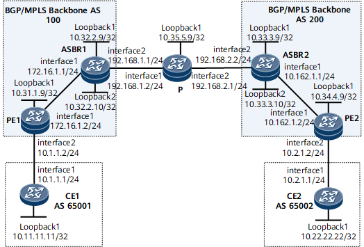
On the network shown in Figure 1, CE1 and CE2 belong to the same VPN; CE1 connects to PE1 in AS100; CE2 connects to PE2 in AS200. The MPLS network between the ASBRs does not support VPN. In other words, there must be a P between the ASBRs. It is required that an LSP be set up between the ASBRs in different ASs to implement inter-AS VPN Option B.
Configuration Notes
When configuring inter-AS VPN Option B with a P between ASBRs, note the following:
There is no need to create VPN instances on ASBRs or configure ASBRs to filter VPNv4 routes based on VPN targets.
LDP and IGP are required between ASBRs.
A multi-hop MP-EBGP peer relationship needs to be set up between ASBRs.
Configuration Roadmap
The configuration roadmap is as follows:
Configure an IGP on the MPLS backbone network for IP connectivity between the ASBR and PE in the same AS, and set up an MPLS LDP LSP between the ASBR and PE in the same AS.
Set up EBGP peer relationships between PEs and CEs and set up MP-IBGP peer relationships between the PEs and ASBRs.
Configure VPN instances on PEs, but not ASBRs.
Set up an EBGP peer relationship between ASBRs and set up an MPLS LDP LSP.
Data Preparation
To complete the configuration, you need the following data:
MPLS LSR IDs of PE1 (10.31.1.9), ASBR1 (10.32.2.9), ASBR2 (10.33.3.9), PE2 (10.34.4.9), and P (10.35.5.9)
Name (vpn1), RD (100:1 and 200:1), and export and import VPN targets (1:1) of the VPN instance on PEs
Procedure
- On the MPLS backbone networks in AS100 and AS200, configure an IGP to interconnect the PE and ASBR on each network.
This example uses OSPF as the IGP. For configuration details, see Configuration Files in this section.

The 32-bit IP address of the loopback interface that functions as the LSR ID needs to be advertised by using OSPF.
After the configurations are complete, the OSPF neighbor relationship can be established between the ASBR and PE in the same AS. Run the display ospf peer command. The command output shows that the neighbor relationship is in the Full state.
The ASBR and PE in the same AS can learn and successfully ping the IP address of each other's loopback interface.
- Configure MPLS and MPLS LDP both globally and per interface on each node of the MPLS backbone networks in AS100 and AS200 and set up LDP LSPs.
For configuration details, see Configuration Files in this section.
- Configure basic BGP/MPLS IP VPN functions on PE1 and PE2.
The VPN targets of the VPN instances on PE1 and PE2 must be the same.
For configuration details, see Configuration Files in this section.
- Set up an MPLS LDP LSP and establish an MP-EBGP neighbor relationship between the ASBRs.
Configure an IGP between the ASBRs. This example uses OSPF as the IGP.
# Configure ASBR1.
<ASBR1> system-view
[~ASBR1] interface gigabitethernet 0/1/8
[~ASBR1-GigabitEthernet0/1/8] ip address 192.168.1.1 24
[*ASBR1-GigabitEthernet0/1/8] commit
[*ASBR1-GigabitEthernet0/1/8] quit
[*ASBR1] ospf 2
[*ASBR1-ospf-2] area 0
[*ASBR1-ospf-2-area-0.0.0.0] network 10.32.2.10 0.0.0.0
[*ASBR1-ospf-2-area-0.0.0.0] network 192.168.1.0 0.0.0.255
[*ASBR1-ospf-2-area-0.0.0.0] quit
[*ASBR1-ospf-2] commit
[~ASBR1-ospf-2] quit
[~ASBR1] quit
The process ID of OSPF running between the ASBRs must be different from that of OSPF running in each AS.
The configurations of ASBR2 and the P are similar to the configuration of ASBR1. For configuration details, see Configuration Files in this section.
# Set up an MPLS LDP LSP between the ASBRs.
<ASBR1> system-view
[~ASBR1] mpls lsr-id 10.32.2.9
[*ASBR1] mpls
[*ASBR1-mpls] quit
[*ASBR1] mpls ldp
[*ASBR1-mpls-ldp] quit
[*ASBR1] interface gigabitethernet0/1/8
[*ASBR1-GigabitEthernet0/1/8] mpls
[*ASBR1-GigabitEthernet0/1/8] mpls ldp
[*ASBR1-GigabitEthernet0/1/8] commit
[~ASBR1-GigabitEthernet0/1/8] quit
The configurations of ASBR2 and the P are similar to the configuration of ASBR1. For configuration details, see Configuration Files in this section.
After completing the configurations, run the display mpls ldp lsp command on the ASBRs. The command output shows that there is an MPLS LDP LSP between the ASBRs.
<ASBR1>display mpls ldp lsp
 LDP LSP Information
 -------------------------------------------------------------------------------
 DestAddress/Mask   In/OutLabel    UpstreamPeer    NextHop          OutInterface
 -------------------------------------------------------------------------------
 10.32.2.9/32       3/NULL         10.35.5.9       127.0.0.1         Loop1
*10.32.2.9/32       Liberal/16                     DS/5.5.5.5
 10.33.3.9/32       NULL/19        -               192.168.1.1       GE0/1/8
 10.33.3.9/32       16/19          10.35.5.9       192.168.1.1       GE0/1/8
 10.35.5.9/32       NULL/3         -               192.168.1.1       GE0/1/8
 10.35.5.9/32       17/3           10.35.5.9       192.168.1.1       GE0/1/8
 -------------------------------------------------------------------------------
 TOTAL: 5 Normal LSP(s) Found.
 TOTAL: 1 Liberal LSP(s) Found.
 TOTAL: 0 Frr LSP(s) Found.
An asterisk (*) before an LSP means the LSP is not established
 An asterisk (*) before a Label means the USCB or DSCB is stale
 An asterisk (*) before an UpstreamPeer means the session is stale
 An asterisk (*) before a DS means the session is stale
 An asterisk (*) before a NextHop means the LSP is FRR LSP
# Set up an MP-EBGP peer relationship between ASBR1 and ASBR2, and configure the ASBRs not to filter received VPNv4 routes based on VPN targets.
[~ASBR1] bgp 100
[*ASBR1-bgp] peer 10.33.3.10 as-number 200
[*ASBR1-bgp] peer 10.33.3.10 connect-interface loopback1
[*ASBR1-bgp] peer 10.33.3.10 ebgp-max-hop 3
[*ASBR1-bgp] ipv4-family vpnv4
[*ASBR1-bgp-af-vpnv4] peer 10.33.3.10 enable
[*ASBR1-bgp-af-vpnv4] undo policy vpn-target
[*ASBR1-bgp-af-vpnv4] commit
[~ASBR1-bgp-af-vpnv4] quit
[~ASBR1-bgp] quit
- Verify the configuration.
After the configurations are complete, CEs can learn routes to each other's loopback interface, and CE1 and CE2 can ping each other.
The following example uses the command output on CE1.
<CE1> display ip routing-table
Route Flags: R - relay, D - download to fib, T - to vpn-instance, B - black hole route
------------------------------------------------------------------------------
Routing Table: _public_
         Destinations : 8        Routes : 8
Destination/Mask    Proto  Pre  Cost     Flags NextHop         Interface
       10.1.1.0/24  Direct 0    0             D  10.1.1.1        GigabitEthernet0/1/0
       10.1.1.1/32  Direct 0    0             D  127.0.0.1       GigabitEthernet0/1/0
     10.1.1.255/32  Direct 0    0             D  127.0.0.1       GigabitEthernet0/1/0
   10.22.22.22/32  EBGP   255  0             D  10.1.1.2        GigabitEthernet0/1/0
      127.0.0.0/8   Direct 0    0             D  127.0.0.1       InLoopBack0
      127.0.0.1/32  Direct 0    0             D  127.0.0.1       InLoopBack0
127.255.255.255/32  Direct 0    0             D  127.0.0.1       InLoopBack0
255.255.255.255/32  Direct 0    0             D  127.0.0.1       InLoopBack0
<CE1> ping -a 10.11.11.11 10.22.22.22
  PING 10.22.22.22: 56  data bytes, press CTRL_C to break
    Reply from 10.22.22.22: bytes=56 Sequence=1 ttl=252 time=120 ms
    Reply from 10.22.22.22: bytes=56 Sequence=2 ttl=252 time=73 ms
    Reply from 10.22.22.22: bytes=56 Sequence=3 ttl=252 time=111 ms
    Reply from 10.22.22.22: bytes=56 Sequence=4 ttl=252 time=86 ms
    Reply from 10.22.22.22: bytes=56 Sequence=5 ttl=252 time=110 ms
  --- 10.22.22.22 ping statistics ---
    5 packet(s) transmitted
    5 packet(s) received
    0.00% packet loss
    round-trip min/avg/max = 73/100/120 ms
Run the display bgp vpnv4 all routing-table command on the ASBRs. The command output shows the VPNv4 routes on the ASBRs.
The following example uses the command output on ASBR1.
<ASBR1> display bgp vpnv4 all routing-table
 BGP Local router ID is 10.32.2.9
 Status codes: * - valid, > - best, d - damped, x - best external, a - add path,
               h - history,  i - internal, s - suppressed, S - Stale
               Origin : i - IGP, e - EGP, ? - incomplete
 RPKI validation codes: V - valid, I - invalid, N - not-found


 Total number of routes from all PE: 2
 Route Distinguisher: 100:1


      Network            NextHop        MED        LocPrf    PrefVal Path/Ogn

 *>i  10.11.11.11/32   10.31.1.9       0          100        0      ?
 Route Distinguisher: 200:1


      Network            NextHop        MED        LocPrf    PrefVal Path/Ogn

 *>   10.22.22.22/24   192.168.1.2                           0      200?
Configuration Files
CE1 configuration file
#
 sysname CE1
#
interface GigabitEthernet0/1/0
 undo shutdown
 ip address 10.1.1.1 255.255.255.0
#
interface Loopback 1
 undo shutdown
 ip address 10.11.11.11 255.255.255.255
#
bgp 65001
 peer 10.1.1.2 as-number 100
 #
 ipv4-family unicast
  undo synchronization
  peer 10.1.1.2 enable
  network 10.11.11.11 255.255.255.255
return
PE1 configuration file
#
 sysname PE1
#
ip vpn-instance vpn1
 ipv4-family
  route-distinguisher 100:1
  apply-label per-instance
  vpn-target 1:1 export-extcommunity
  vpn-target 1:1 import-extcommunity
#
mpls lsr-id 10.31.1.9
#
mpls
#
mpls ldp
#
interface GigabitEthernet0/1/0
 undo shutdown
 ip address 172.16.1.2 255.255.255.0
 mpls
 mpls ldp
#
interface GigabitEthernet0/1/8
 undo shutdown
 ip binding vpn-instance vpn1
 ip address 10.1.1.2 255.255.255.0
#
interface LoopBack1
 ip address 10.31.1.9 255.255.255.255
#
bgp 100
 peer 10.32.2.9 as-number 100
 peer 10.32.2.9 connect-interface LoopBack1
 #
 ipv4-family unicast
  undo synchronization
  peer 10.32.2.9 enable
 #
 ipv4-family vpnv4
  policy vpn-target
  peer 10.32.2.9 enable
#
 ipv4-family vpn-instance vpn1
  peer 10.1.1.1 as-number 65001
#
ospf 1
 area 0.0.0.0
  network 10.31.1.9 0.0.0.0
  network 172.16.1.0 0.0.0.255
#
return
ASBR1 configuration file
#
 sysname ASBR1
#
mpls lsr-id 10.32.2.9
#
mpls
#
mpls ldp
#
interface GigabitEthernet0/1/0
 undo shutdown
 ip address 172.16.1.1 255.255.255.0
 mpls
 mpls ldp
#
interface GigabitEthernet0/1/8
 undo shutdown
 ip address 192.168.1.1 255.255.255.0
 mpls
 mpls ldp
#
interface LoopBack1
 ip address 10.32.2.9 255.255.255.255
#
interface LoopBack2
 ip address 10.32.2.10 255.255.255.255
#
bgp 100
 peer 10.31.1.9 as-number 100
 peer 10.31.1.9 connect-interface LoopBack1
 peer 10.33.3.10 as-number 200
 peer 10.33.3.10 connect-interface LoopBack2
 peer 10.33.3.10 ebgp-max-hop 3
 #
 ipv4-family unicast
  undo synchronization
  peer 10.33.3.9 enable
  peer 10.31.1.9 enable
 #
 ipv4-family vpnv4
  undo policy vpn-target
  peer 10.31.1.9 enable
  peer 10.33.3.9 enable
#
ospf 1
 area 0.0.0.0
  network 10.32.2.9 0.0.0.0
  network 172.16.1.0 0.0.0.255
#
ospf 2
 area 0.0.0.0
  network 10.32.2.10 0.0.0.0
  network 192.168.1.0 0.0.0.255
#
return
P configuration file
#
 sysname P
#
mpls lsr-id 10.35.5.9
#
mpls
#
mpls ldp
#
interface GigabitEthernet0/1/0
 undo shutdown
 ip address 192.168.1.2 255.255.255.0
 mpls
 mpls ldp
#
interface GigabitEthernet0/1/8
 undo shutdown
 ip address 192.168.2.1 255.255.255.0
 mpls
 mpls ldp
#
interface LoopBack1
 ip address 10.35.5.9 255.255.255.255
#
ospf 1
 area 0.0.0.0
  network 10.35.5.9 0.0.0.0
  network 192.168.1.0 0.0.0.255
  network 192.168.2.0 0.0.0.255
#
return
ASBR2 configuration file
#
 sysname ASBR2
#
mpls lsr-id 10.33.3.9
#
mpls
#
mpls ldp
#
interface GigabitEthernet0/1/0
 undo shutdown
 ip address 10.162.1.1 255.255.255.0
 mpls
 mpls ldp
#
interface GigabitEthernet0/1/8
 undo shutdown
 ip address 192.168.2.2 255.255.255.0
 mpls
 mpls ldp
#
interface LoopBack1
 ip address 10.33.3.9 255.255.255.255
#
interface LoopBack2
 ip address 10.33.3.10 255.255.255.255
#
bgp 200
 peer 10.32.2.10 as-number 100
 peer 10.32.2.10 connect-interface LoopBack2
 peer 10.32.2.10 ebgp-max-hop 3
 peer 10.34.4.9 as-number 200
 peer 10.34.4.9 connect-interface LoopBack1
 #
 ipv4-family unicast
  undo synchronization
  peer 10.32.2.9 enable
  peer 10.34.4.9 enable
 #
 ipv4-family vpnv4
  undo policy vpn-target
  peer 10.34.4.9 enable
  peer 10.32.2.9 enable
#
ospf 1
 area 0.0.0.0
  network 10.33.3.9 0.0.0.0
  network 10.162.1.0 0.0.0.255
#
ospf 2
 area 0.0.0.0
  network 10.33.3.10 0.0.0.0
  network 192.168.2.0 0.0.0.255
#
return
PE2 configuration file
#
 sysname PE2
#
ip vpn-instance vpn1
 ipv4-family
  route-distinguisher 200:1
  apply-label per-instance
  vpn-target 1:1 export-extcommunity
  vpn-target 1:1 import-extcommunity
#
mpls lsr-id 10.34.4.9
#
mpls
#
mpls ldp
#
interface GigabitEthernet0/1/0
 undo shutdown
 ip address 10.162.1.2 255.255.255.0
 mpls
 mpls ldp
#
interface GigabitEthernet0/1/8
 undo shutdown
 ip binding vpn-instance vpn1
 ip address 10.2.1.2 255.255.255.0
#
interface LoopBack1
 ip address 10.34.4.9 255.255.255.255
#
bgp 200
 peer 10.33.3.9 as-number 200
 peer 10.33.3.9 connect-interface LoopBack1
 #
 ipv4-family unicast
  undo synchronization
  peer 10.33.3.9 enable
 #
 ipv4-family vpnv4
  policy vpn-target
  peer 10.33.3.9 enable
#
 ipv4-family vpn-instance vpn1
  peer 10.2.1.1 as-number 65002
#
ospf 1
 area 0.0.0.0
  network 10.34.4.9 0.0.0.0
  network 10.162.1.0 0.0.0.255
#
return
CE2 configuration file
#
 sysname CE2
#
interface GigabitEthernet0/1/0
 undo shutdown
 ip address 10.2.1.1 255.255.255.0
#
interface Loopback 1
 undo shutdown
 ip address 10.22.22.22 255.255.255.255
#
bgp 65002
 peer 10.2.1.2 as-number 200
 #
 ipv4-family unicast
  undo synchronization
  peer 10.2.1.2 enable
  network 10.22.22.22 255.255.255.255
#
return