Example for Configuring Inter-AS VPN Option B with ASBRs Functioning as PEs
In a scenario in which the backbone network spans two ASs, ASBRs need to advertise VPNv4 routes through MP-EBGP and ASBRs also need to function as PEs.
Networking Requirements
In inter-AS VPN Option B networking, the ASBRs function as inter-AS devices to transmit VPNv4 routes and also function as PEs to manage VPN routes. In this case, inter-AS VPN Option B with ASBRs functioning as PEs can be deployed. This decreases the number of PEs being deployed but imposes higher requirements on ASBR performance.
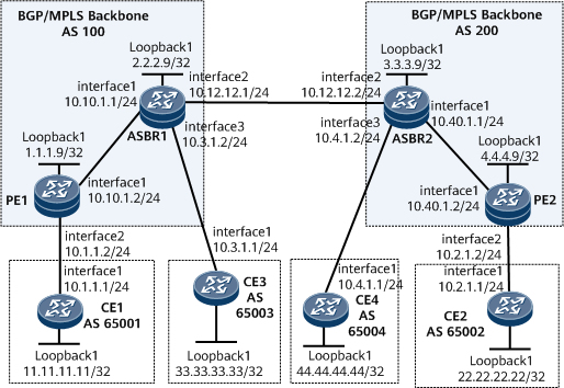
On the network shown in Figure 1, it is required that inter-AS VPN Option B be configured and ASBRs be configured to function as PEs to interconnect the CEs.
Configuration Notes
When configuring inter-AS VPN Option B with ASBRs functioning as PEs, note the following:
VPN instances must be configured on ASBRs and ASBRs and CEs need to communicate.
The ASBRs do not filter the received VPNv4 routes based on VPN targets.
Configuration Roadmap
The configuration roadmap is as follows:
Configure an IGP on the MPLS backbone network for IP connectivity between the ASBR and PE in the same AS, and set up an MPLS LDP LSP between the ASBR and PE in the same AS.
Set up MP-IBGP peer relationships between PEs and ASBRs.
Configure VPN instances on PEs and ASBRs and set up EBGP peer relationships between the PEs, ASBRs, and CEs.
Enable MPLS on the interface that connects one ASBR to the other ASBR and set up an MP-EBGP peer relationship between the ASBRs.
Data Preparation
To complete the configuration, you need the following data:
MPLS LSR IDs of PE1 (1.1.1.9), ASBR1 (2.2.2.9), ASBR2 (3.3.3.9), and PE2 (4.4.4.9)
Name (vpna), RD (100:1, 100:3, 200:1 and 200:4), and export and import VPN targets (1:1) of the VPN instance on each PE and ASBRs
Procedure
- On the MPLS backbone networks in AS100 and AS200, configure an IGP to interconnect the PE and ASBR on each network.
This example uses OSPF as the IGP. For configuration details, see Configuration Files in this section.
After the configurations are complete, the OSPF neighbor relationship can be established between the ASBR and PE in the same AS. Run the display ospf peer command. The command output shows that the neighbor relationship is in the Full state. The ASBR and PE in the same AS can learn and ping the IP address of each other's loopback interface.
- Configure MPLS and MPLS LDP both globally and per interface on each node of the MPLS backbone networks in AS100 and AS200 and set up LDP LSPs.
# Configure PE1.
[~PE1] mpls lsr-id 1.1.1.9
[*PE1] mpls
[*PE1-mpls] quit
[*PE1] mpls ldp
[*PE1-mpls-ldp] quit
[*PE1] interface gigabitethernet 0/1/0
[*PE1-GigabitEthernet0/1/0] mpls
[*PE1-GigabitEthernet0/1/0] mpls ldp
[*PE1-GigabitEthernet0/1/0] commit
[~PE1-GigabitEthernet0/1/0] quit
The configuration of PE2 is similar to the configuration of PE1. For configuration details, see Configuration Files in this section.
# Configure ASBR1.
[~ASBR1] mpls lsr-id 2.2.2.9
[*ASBR1] mpls
[*ASBR1-mpls] quit
[*ASBR1] mpls ldp
[*ASBR1-mpls-ldp] quit
[*ASBR1] interface gigabitethernet 0/1/0
[*ASBR1-GigabitEthernet0/1/0] mpls
[*ASBR1-GigabitEthernet0/1/0] mpls ldp
[*ASBR1-GigabitEthernet0/1/0] commit
[~ASBR1-GigabitEthernet0/1/0] quit
The configuration of ASBR2 is similar to the configuration of ASBR1. For configuration details, see Configuration Files in this section.
After the configurations are complete, the LDP session can be established between the PE and ASBR. Run the display mpls ldp session command on each device. The command output shows that the Status field is Operational. The following example uses the command output on PE1.
<PE1> display mpls ldp session LDP Session(s) in Public Network Codes: LAM(Label Advertisement Mode), SsnAge Unit(DDD:HH:MM) An asterisk (*) before a session means the session is being deleted. ------------------------------------------------------------------------- PeerID Status LAM SsnRole SsnAge KASent/Rcv ------------------------------------------------------------------------- 2.2.2.9:0 Operational DU Passive 0000:00:01 5/5 ------------------------------------------------------------------------- TOTAL: 1 session(s) Found. - Set up an MP-IBGP peer relationship between the PE and ASBR in the same AS.
# Configure PE1.
[~PE1] bgp 100
[*PE1-bgp] peer 2.2.2.9 as-number 100
[*PE1-bgp] peer 2.2.2.9 connect-interface loopback 1
[*PE1-bgp] ipv4-family vpnv4
[*PE1-bgp-af-vpnv4] peer 2.2.2.9 enable
[*PE1-bgp-af-vpnv4] commit
[~PE1-bgp-af-vpnv4] quit
[~PE1-bgp] quit
The configuration of PE2 is similar to the configuration of PE1. For configuration details, see Configuration Files in this section.
# Configure ASBR1.
[~ASBR1] bgp 100
[*ASBR1-bgp] peer 1.1.1.9 as-number 100
[*ASBR1-bgp] peer 1.1.1.9 connect-interface loopback 1
[*ASBR1-bgp] ipv4-family vpnv4
[*ASBR1-bgp-af-vpnv4] peer 1.1.1.9 enable
[*ASBR1-bgp-af-vpnv4] commit
[~ASBR1-bgp-af-vpnv4] quit
[~ASBR1-bgp] quit
The configuration of ASBR2 is similar to the configuration of ASBR1. For configuration details, see Configuration Files in this section.
After completing the configurations, run the display bgp vpnv4 all peer command on the PE or ASBR. The command output shows that an MP-IBGP peer relationship has been established between the PE and ASBR in the same AS. The following example uses the command output on PE1.
<PE1> display bgp vpnv4 all peer

 BGP local router ID : 1.1.1.9
 Local AS number : 100
 Total number of peers : 1         Peers in established state : 1

  Peer            V          AS  MsgRcvd  MsgSent  OutQ  Up/Down       State  PrefRcv

  2.2.2.9         4         100       54       59     0 00:45:03 Established    2
- Configure VPN instances on PEs and ASBRs and connect the CEs to the PEs through the VPN instances.
# Configure PE1.
[~PE1] ip vpn-instance vpna
[*PE1-vpn-instance-vpna] ipv4-family
[*PE1-vpn-instance-vpna-af-ipv4] route-distinguisher 100:1
[*PE1-vpn-instance-vpna-af-ipv4] vpn-target 1:1 both
[*PE1-vpn-instance-vpna-af-ipv4] quit
[*PE1-vpn-instance-vpna] quit
[*PE1] interface gigabitethernet 0/1/8
[*PE1-GigabitEthernet0/1/8] ip binding vpn-instance vpna
[*PE1-GigabitEthernet0/1/8] ip address 10.1.1.2 24
[*PE1-GigabitEthernet0/1/8] commit
[~PE1-GigabitEthernet0/1/8] quit
The configurations of PE2, ASBR1, and ASBR2 are similar to the configuration of PE1. For configuration details, see Configuration Files in this section.
After completing the configurations, run the display ip vpn-instance verbose command on the PE or ASBR to view the configurations of VPN instances. The following example uses the command output on PE1.
<PE1> display ip vpn-instance verbose Total VPN-Instances configured : 1 Total IPv4 VPN-Instances configured : 1 Total IPv6 VPN-Instances configured : 0 VPN-Instance Name and ID : vpna, 1 Interfaces : GigabitEthernet0/1/8 Address family ipv4 Create date : 2009/09/18 11:30:35 Up time : 0 days, 00 hours, 05 minutes and 19 seconds Vrf Status : UP Route Distinguisher : 100:1 Export VPN Targets : 1:1 Import VPN Targets : 1:1 Label policy: label per route The diffserv-mode Information is : uniform The ttl-mode Information is : pipe - Set up EBGP peer relationships between the PEs, ASBRs, and CEs, and import VPN routes to the loopback interfaces of the CEs.
# Configure CE1.
[~CE1] interface loopback 1
[*CE1-Loopback1] ip address 11.11.11.11 32
[*CE1-Loopback1] quit
[*CE1] bgp 65001
[*CE1-bgp] peer 10.1.1.2 as-number 100
[*CE1-bgp] network 11.11.11.11 32
[*CE1-bgp] quit
[*CE1] commit
The configurations of CE2, CE3, and CE4 are similar to the configuration of CE1. For configuration details, see Configuration Files in this section.
# Configure PE1.
[~PE1] bgp 100
[~PE1-bgp] ipv4-family vpn-instance vpna
[*PE1-bgp-vpna] peer 10.1.1.1 as-number 65001
[*PE1-bgp-vpna] commit
[~PE1-bgp-vpna] quit
The configurations of PE2, ASBR1, and ASBR2 are similar to the configuration of PE1. For configuration details, see Configuration Files in this section.
After completing the configurations, run the display bgp vpnv4 vpn-instance peer command on the PEs or ASBRs. The command output shows that BGP peer relationships have been established between PEs and CEs. The following example uses the peer relationship between PE1 and CE1.
<PE1> display bgp vpnv4 vpn-instance vpna peer
 BGP local router ID : 10.1.1.2
 Local AS number : 100
 Total number of peers : 1            Peers in established state : 1
  Peer            V    AS  MsgRcvd  MsgSent    OutQ  Up/Down    State        PrefRcv
  10.1.1.1        4   65001  11     9          0     00:06:37   Established  1
- Enable MPLS on the interface that connects one ASBR to the other ASBR.
[~ASBR1] interface GigabitEthernet 0/1/8
[~ASBR1-GigabitEthernet0/1/8] ip address 10.12.12.1 24
[*ASBR1-GigabitEthernet0/1/8] mpls
[*ASBR1-GigabitEthernet0/1/8] quit
[*ASBR1] commit
The configuration of ASBR2 is similar to the configuration of ASBR1. For configuration details, see Configuration Files in this section.
- Set up an MP-EBGP peer relationship between the ASBRs, and configure the ASBRs not to filter received VPNv4 routes based on VPN targets.
[*ASBR1] bgp 100
[*ASBR1-bgp] peer 10.12.12.2 as-number 200
[*ASBR1-bgp] ipv4-family vpnv4
[*ASBR1-bgp-af-vpnv4] peer 10.12.12.2 enable
[*ASBR1-bgp-af-vpnv4] undo policy vpn-target
[*ASBR1-bgp-af-vpnv4] commit
[*ASBR1-bgp-af-vpnv4] quit
[*ASBR1-bgp] quit
The configuration of ASBR2 is similar to the configuration of ASBR1. For configuration details, see Configuration Files in this section.

The ASBR does not filter the received VPNv4 routes based on VPN targets. Instead, it advertises the received routes to the peer ASBR or the PE in the same AS. The VPN routing table on the ASBR is used to match the VPN targets. Routes that have matching VPN targets in the VPN routing table on the ASBR are received.
- Verify the configuration.
After completing the configurations, run the display ip routing-table command on the CEs. The command output shows the routes learned by the local CE from other CEs. The following example uses the command output on CE1.
<CE3> display ip routing-table
Route Flags: R - relay, D - download to fib, T - to vpn-instance, B - black hole route
------------------------------------------------------------------------------
Routing Table: _public_
         Destinations : 11        Routes : 11
Destination/Mask    Proto  Pre  Cost      Flags  NextHop         Interface
       10.3.1.0/24  Direct 0    0             D  10.3.1.1        GigabitEthernet0/1/0
       10.3.1.1/32  Direct 0    0             D  127.0.0.1       GigabitEthernet0/1/0
     10.3.1.255/32  Direct 0    0             D  127.0.0.1       GigabitEthernet0/1/0
      11.11.11.11/32  EBGP   255  0            RD  10.3.1.2        GigabitEthernet0/1/0
      22.22.22.22/32  EBGP   255  0            RD  10.3.1.2        GigabitEthernet0/1/0
    33.33.33.33/32  Direct 0    0             D  127.0.0.1       LoopBack1
      44.44.44.44/32  EBGP   255  0            RD  10.3.1.2        GigabitEthernet0/1/0
      127.0.0.0/8   Direct 0    0             D  127.0.0.1       InLoopBack0
      127.0.0.1/32  Direct 0    0             D  127.0.0.1       InLoopBack0
127.255.255.255/32  Direct 0    0             D  127.0.0.1       InLoopBack0
255.255.255.255/32  Direct 0    0             D  127.0.0.1       InLoopBack0
Run the display bgp vpnv4 all routing-table command on an ASBR. The command output shows the VPNv4 routes on the ASBRs. The following example uses the command output on ASBR1.
<ASBR1> display bgp vpnv4 all routing-table
 BGP Local router ID is 2.2.2.9
 Status codes: * - valid, > - best, d - damped, x - best external, a - add path,
               h - history,  i - internal, s - suppressed, S - Stale
               Origin : i - IGP, e - EGP, ? - incomplete
 RPKI validation codes: V - valid, I - invalid, N - not-found


 Total number of routes from all PE: 4
 Route Distinguisher: 100:1


      Network            NextHop        MED        LocPrf    PrefVal Path/Ogn

 *>i  11.11.11.11/32     1.1.1.9                    100        0      ?
 Route Distinguisher: 200:1


      Network            NextHop        MED        LocPrf    PrefVal Path/Ogn

 *>   22.22.22.22/32     3.3.3.9                             0       200?
 Route Distinguisher: 100:3


      Network            NextHop        MED        LocPrf    PrefVal Path/Ogn
*>i  33.33.33.33/32     0.0.0.0         0                     0      ?
 Route Distinguisher: 200:4


      Network            NextHop        MED        LocPrf    PrefVal Path/Ogn
 *>i  44.44.44.44/32        3.3.3.9         0          100        0      200?
Configuration Files
CE1 configuration file
#
 sysname CE1
#
interface GigabitEthernet0/1/0
 undo shutdown
 ip address 10.1.1.1 255.255.255.0
#
interface Loopback1
 undo shutdown
 ip address 11.11.11.11 255.255.255.255
#
bgp 65001
 peer 10.1.1.2 as-number 100
 #
 ipv4-family unicast
  undo synchronization
  peer 10.1.1.2 enable
  network 11.11.11.11 255.255.255.255
return
PE1 configuration file
#
 sysname PE1
#
ip vpn-instance vpna
 ipv4-family
  route-distinguisher 100:1
  apply-label per-instance
  vpn-target 1:1 export-extcommunity
  vpn-target 1:1 import-extcommunity
#
mpls lsr-id 1.1.1.9
#
mpls
#
mpls ldp
#
interface GigabitEthernet0/1/0
 undo shutdown
 ip address 10.10.1.2 255.255.255.0
 mpls
 mpls ldp
#
interface GigabitEthernet0/1/8
 undo shutdown
 ip binding vpn-instance vpna
 ip address 10.1.1.2 255.255.255.0
#
interface LoopBack1
 ip address 1.1.1.9 255.255.255.255
#
bgp 100
 peer 2.2.2.9 as-number 100
 peer 2.2.2.9 connect-interface LoopBack1
 #
 ipv4-family unicast
  undo synchronization
  peer 2.2.2.9 enable
 #
 ipv4-family vpnv4
  policy vpn-target
  peer 2.2.2.9 enable
#
 ipv4-family vpn-instance vpna
  peer 10.1.1.1 as-number 65001
#
ospf 1
 area 0.0.0.0
  network 1.1.1.9 0.0.0.0
  network 10.10.1.0 0.0.0.255
#
return
ASBR1 configuration file
#
 sysname ASBR1
#
ip vpn-instance vpna
 ipv4-family
  route-distinguisher 100:3
  apply-label per-instance
  vpn-target 1:1 export-extcommunity
  vpn-target 1:1 import-extcommunity
#
mpls lsr-id 2.2.2.9
#
mpls
#
mpls ldp
#
interface GigabitEthernet0/1/0
 undo shutdown
 ip address 10.10.1.1 255.255.255.0
 mpls
 mpls ldp
#
interface GigabitEthernet0/1/8
 undo shutdown
 ip address 10.12.12.1 255.255.255.0
 mpls
#
interface GigabitEthernet0/1/16
 undo shutdown
 ip binding vpn-instance vpna
 ip address 10.3.1.2 255.255.255.0
#
interface LoopBack1
 ip address 2.2.2.9 255.255.255.255
#
bgp 100
 peer 10.12.12.2 as-number 200
 peer 1.1.1.9 as-number 100
 peer 1.1.1.9 connect-interface LoopBack1
 #
 ipv4-family unicast
  undo synchronization
  peer 10.12.12.2 enable
  peer 1.1.1.9 enable
 #
 ipv4-family vpnv4
  undo policy vpn-target
  peer 1.1.1.9 enable
  peer 10.12.122.2 enable
#
 ipv4-family vpn-instance vpna
  peer 10.3.1.1 as-number 65003
#
ospf 1
 area 0.0.0.0
  network 2.2.2.9 0.0.0.0
  network 10.10.1.0 0.0.0.255
#
return
CE3 configuration file
#
 sysname CE3
#
interface GigabitEthernet0/1/0
 undo shutdown
 ip address 10.3.1.1 255.255.255.0
#
interface Loopback1
 undo shutdown
 ip address 33.33.33.33 255.255.255.255
#
bgp 65003
 peer 10.3.1.2 as-number 100
 #
 ipv4-family unicast
  undo synchronization
  peer 10.3.1.2 enable
  network 33.33.33.33 255.255.255.255
return
ASBR2 configuration file
#
 sysname ASBR2
#
ip vpn-instance vpna
 ipv4-family
  route-distinguisher 200:4
  apply-label per-instance
  vpn-target 1:1 export-extcommunity
  vpn-target 1:1 import-extcommunity
#
mpls lsr-id 3.3.3.9
#
mpls
#
mpls ldp
#
interface GigabitEthernet0/1/0
 undo shutdown
 ip address 10.40.1.1 255.255.255.0
 mpls
 mpls ldp
#
interface GigabitEthernet0/1/8
 undo shutdown
 ip address 10.12.12.2 255.255.255.0
 mpls
#
interface GigabitEthernet0/1/16
 undo shutdown
 ip binding vpn-instance vpna
 ip address 10.4.1.2 255.255.255.0
#
interface LoopBack1
 ip address 3.3.3.9 255.255.255.255
#
bgp 200
 peer 10.12.12.1 as-number 100
 peer 4.4.4.9 as-number 200
 peer 4.4.4.9 connect-interface LoopBack1
 #
 ipv4-family unicast
  undo synchronization
  peer 10.12.12.1 enable
  peer 4.4.4.9 enable
 #
 ipv4-family vpnv4
  undo policy vpn-target
  peer 4.4.4.9 enable
  peer 10.12.12.1 enable
#
 ipv4-family vpn-instance vpna
  peer 10.4.1.1 as-number 65004
#
ospf 1
 area 0.0.0.0
  network 3.3.3.9 0.0.0.0
  network 10.40.1.0 0.0.0.255
#
return
CE4 configuration file
#
 sysname CE4
#
interface GigabitEthernet0/1/0
 undo shutdown
 ip address 10.4.1.1 255.255.255.0
#
interface Loopback1
 undo shutdown
 ip address 44.44.44.44 255.255.255.255
#
bgp 65004
 peer 10.4.1.2 as-number 200
 #
 ipv4-family unicast
  undo synchronization
  peer 10.4.1.2 enable
  network 44.44.44.44 255.255.255.255
return
PE2 configuration file
#
 sysname PE2
#
ip vpn-instance vpna
 ipv4-family
  route-distinguisher 200:1
  apply-label per-instance
  vpn-target 1:1 export-extcommunity
  vpn-target 1:1 import-extcommunity
#
mpls lsr-id 4.4.4.9
#
mpls
#
mpls ldp
#
interface GigabitEthernet0/1/8
 undo shutdown
 ip binding vpn-instance vpna
 ip address 10.2.1.2 255.255.255.0
#
interface GigabitEthernet0/1/0
 undo shutdown
 ip address 10.40.1.2 255.255.255.0
 mpls
 mpls ldp
#
interface LoopBack1
 ip address 4.4.4.9 255.255.255.255
#
bgp 200
 peer 3.3.3.9 as-number 200
 peer 3.3.3.9 connect-interface LoopBack1
 #
 ipv4-family unicast
  undo synchronization
  peer 3.3.3.9 enable
 #
 ipv4-family vpnv4
  policy vpn-target
  peer 3.3.3.9 enable
#
 ipv4-family vpn-instance vpna
  peer 10.2.1.1 as-number 65002
#
ospf 1
 area 0.0.0.0
  network 4.4.4.9 0.0.0.0
  network 10.40.1.0 0.0.0.255
#
return
CE2 configuration file
#
 sysname CE2
#
interface GigabitEthernet0/1/0
 undo shutdown
 ip address 10.2.1.1 255.255.255.0
#
interface Loopback1
 undo shutdown
 ip address 22.22.22.22 255.255.255.255
#
bgp 65002
 peer 10.2.1.2 as-number 200
 #
 ipv4-family unicast
  undo synchronization
  peer 10.2.1.2 enable
  network 22.22.22.22 255.255.255.255
#
return