Example for Configuring Inter-AS VPN Option C (Solution 2)
If no MP-IBGP peer relationship is established between PEs and ASBRs, you can use LDP to allocate labels for BGP and implement the inter-AS VPN OptionC solution.
Networking Requirements
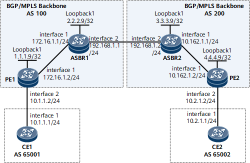
On the network shown in Figure 1, CE1 and CE2 belong to the same VPN. CE1 accesses AS100 through PE1, and CE2 accesses AS200 through PE2.

Interfaces 1 and 2 in this example represent GE 0/1/0 and GE 0/1/8, respectively.
No IBGP peer relationship is needed between a PE and an ASBR. The ASBR learns the labeled BGP routes of the public network in the remote AS from the peer ASBR. These BGP routes are then imported to the IGP. In this manner, LDP can distribute labels for these routes and establish an inter-AS LDP LSP. The inter-AS BGP/MPLS IP VPN can then be implemented in Option C mode.
Configuration Roadmap
The configuration roadmap is as follows:
Advertise the routes of the PEs within an AS to the remote ASBR through BGP, import these routes to the IGP on the remote ASBR, and then advertise these routes to the remote PE through the IGP.
Configure a routing policy on each ASBR, so that each ASBR assigns an MPLS label to the loopback interface route that is received from the PE in the same AS and is to be advertised to the remote ASBR.
Exchange the labeled IPv4 routes between the local and remote ASBRs.
Configure LDP LSPs for the labeled BGP routes of the public network on ASBRs.
Establish an MP-EBGP peer relationship between the PEs of different ASs and specify the maximum hops allowed for an MP-EBGP connection between PEs.
Data Preparation
To complete the configuration, you need the following data:
- MPLS LSR IDs of PEs and ASBRs
- VPN instance name, RD, and VPN target created on each PE
- Routing policy on each ASBR
Procedure
- Configure an IGP on the MPLS backbone networks in AS100 and AS200 so that PEs on each MPLS backbone network can communicate with ASBRs.
This example uses OSPF as the IGP. For configuration details, see Configuration Files in this section.
Advertise the 32-bit IP address of a loopback interface, that is, the LSR ID, using OSPF.
After the configurations are complete, the OSPF neighbor relationship can be established between the ASBR and PE in the same AS. Run the display ospf peer command. The command output shows that the status of the OSPF neighbor relationship is Full.
The following example uses the command output on PE1.
<PE1> display ospf peer
          OSPF Process 1 with Router ID 1.1.1.9
                  Neighbors

 Area 0.0.0.0 interface 172.16.1.2(GE0/1/0)'s neighbors
 Router ID: 2.2.2.9          Address: 172.16.1.1
   State: Full  Mode:Nbr is  Master  Priority: 1
   DR: 2.2.2.9   BDR: 1.1.1.9   MTU: 0
   Dead timer due in 28  sec
   Retrans timer interval: 5
   Neighbor is up for 00:01:04
   Authentication Sequence: [ 0 ]
The ASBR and PE in the same AS can learn the IP address of each other's Loopback 1 interface and ping each other.
- Establish an EBGP peer relationship between the ASBRs.
# Configure ASBR1.
[~ASBR1] bgp 100
[*ASBR1-bgp] peer 192.168.1.2 as-number 200
[*ASBR1-bgp] quit
[*ASBR1] commit
# Configure ASBR2.
[~ASBR2] bgp 200
[*ASBR2-bgp] peer 192.168.1.1 as-number 100
[*ASBR2-bgp] quit
[*ASBR2] commit
After completing the configurations, run the display bgp peer command on each ASBR. The command output shows that the status of the EBGP peer relationship is Established.
The following example uses the command output on ASBR1.
[~ASBR1] display bgp peer BGP local router ID : 172.16.1.1 Local AS number : 100 Total number of peers : 1 Peers in established state : 1 Peer V AS MsgRcvd MsgSent OutQ Up/Down State PrefRcv 192.168.1.2 4 200 129 134 0 01:39:21 Established 1 - Advertise the routes of the PE in an AS to the PE in another AS.
# On ASBR1, advertise the loopback address of PE1 to ASBR2.
[~ASBR1] bgp 100
[*ASBR1-bgp] network 1.1.1.9 32
[*ASBR1-bgp] quit
[*ASBR1] commit
# On ASBR2, advertise the loopback address of PE2 to ASBR1.
[~ASBR2] bgp 200
[*ASBR2-bgp] network 4.4.4.9 32
[*ASBR2-bgp] quit
[*ASBR2] commit
# On ASBR1, import BGP routes to OSPF, and advertise the routes of PE2 to PE1 through OSPF.
[~ASBR1] ospf 1
[*ASBR1-ospf-1] import-route bgp
[*ASBR1-ospf-1] quit
[*ASBR1] commit
# On ASBR2, import BGP routes to OSPF, and advertise the routes of PE1 to PE2 through OSPF.
[~ASBR2] ospf 1
[*ASBR2-ospf-1] import-route bgp
[*ASBR2-ospf-1] quit
[*ASBR2] commit
After completing the configurations, run the display ip routing-table command on each PE. The command output shows routing table information. The following example uses the command output on PE1.
[~PE1] display ip routing-table
Route Flags: R - relay, D - download to fib, T - to vpn-instance, B - black hole route
------------------------------------------------------------------------------
Routing Table: Public
         Destinations : 10        Routes : 10

Destination/Mask    Proto  Pre  Cost     Flags NextHop         Interface

        1.1.1.9/32  Direct 0    0           D  127.0.0.1       InLoopBack0
        2.2.2.9/32  OSPF   10   1           D  172.16.1.1      GigabitEthernet0/1/0
        4.4.4.9/32  O_ASE  150  1           D  172.16.1.1      GigabitEthernet0/1/0
      127.0.0.0/8   Direct 0    0           D  127.0.0.1       InLoopBack0
      127.0.0.1/32  Direct 0    0           D  127.0.0.1       InLoopBack0
127.255.255.255/32  Direct 0    0           D  127.0.0.1       InLoopBack0
     172.16.1.0/24  Direct 0    0           D  172.16.1.2      GigabitEthernet0/1/0
     172.16.1.1/32  Direct 0    0           D  127.0.0.1       GigabitEthernet0/1/0
   172.16.1.255/32  Direct 0    0           D  127.0.0.1       GigabitEthernet0/1/0
255.255.255.255/32  Direct 0    0           D  127.0.0.1       InLoopBack0
- Configure MPLS and MPLS LDP both globally and per interface on each node of the backbone networks in AS100 and AS200 to establish LDP LSPs.
# Configure PE1.
[~PE1] mpls lsr-id 1.1.1.9
[*PE1] mpls
[*PE1-mpls] quit
[*PE1] mpls ldp
[*PE1-mpls-ldp] quit
[*PE1] interface gigabitethernet 0/1/0
[*PE1-GigabitEthernet0/1/0] mpls
[*PE1-GigabitEthernet0/1/0] mpls ldp
[*PE1-GigabitEthernet0/1/0] quit
[*PE1] commit
# Configure ASBR1.
[~ASBR1] mpls lsr-id 2.2.2.9
[*ASBR1] mpls
[*ASBR1-mpls] quit
[*ASBR1] mpls ldp
[*ASBR1-mpls-ldp] quit
[*ASBR1] interface gigabitethernet 0/1/0
[*ASBR1-GigabitEthernet0/1/0] mpls
[*ASBR1-GigabitEthernet0/1/0] mpls ldp
[*ASBR1-GigabitEthernet0/1/0] quit
[*ASBR1] commit
# Configure ASBR2.
[~ASBR2] mpls lsr-id 3.3.3.9
[*ASBR2] mpls
[*ASBR2-mpls] quit
[*ASBR2] mpls ldp
[*ASBR2-mpls-ldp] quit
[*ASBR2] interface gigabitethernet 0/1/0
[*ASBR2-GigabitEthernet0/1/0] mpls
[*ASBR2-GigabitEthernet0/1/0] mpls ldp
[*ASBR2-GigabitEthernet0/1/0] quit
[*ASBR2] commit
# Configure PE2.
[~PE2] mpls lsr-id 4.4.4.9
[*PE2] mpls
[*PE2-mpls] quit
[*PE2] mpls ldp
[*PE2-mpls-ldp] quit
[*PE2] interface gigabitethernet 0/1/0
[*PE2-GigabitEthernet0/1/0] mpls
[*PE2-GigabitEthernet0/1/0] mpls ldp
[*PE2-GigabitEthernet0/1/0] quit
[*PE2] commit
After the configurations are complete, the LDP sessions between PE1 and the ASBR1, and between PE2 and ASBR2 are set up. Run the display mpls ldp session command. The command output shows that the LDP session status is Operational. Run the display mpls ldp lsp command. The command output shows whether LDP LSPs are set up.
The following example uses the command output on PE1.
[~PE1] display mpls ldp session

 LDP Session(s) in Public Network
 Codes: LAM(Label Advertisement Mode), SsnAge Unit(DDDD:HH:MM)
 An asterisk (*) before a session means the session is being deleted.
 ------------------------------------------------------------------------------
 PeerID             Status      LAM  SsnRole  SsnAge      KASent/Rcv
 ------------------------------------------------------------------------------
 2.2.2.9:0          Operational DU   Passive  0000:00:01  5/5
 ------------------------------------------------------------------------------
 TOTAL: 1 session(s) Found.

[~PE1] display mpls ldp lsp
 LDP LSP Information
 -------------------------------------------------------------------------------
 DestAddress/Mask   In/OutLabel   UpstreamPeer   NextHop         OutInterface
 -------------------------------------------------------------------------------
 1.1.1.9/32         3/NULL        2.2.2.9        127.0.0.1       InLoop0
*1.1.1.9/32         Liberal/1024                 DS/2.2.2.9
 2.2.2.9/32         NULL/3        -              172.16.1.1      GE0/1/0
 2.2.2.9/32         1024/3        2.2.2.9        172.16.1.1      GE0/1/0
 -------------------------------------------------------------------------------
 TOTAL: 3 Normal LSP(s) Found.
 TOTAL: 1 Liberal LSP(s) Found.
 TOTAL: 0 Frr LSP(s) Found.
An asterisk (*) before an LSP means the LSP is not established
 An asterisk (*) before a Label means the USCB or DSCB is stale
 An asterisk (*) before an UpstreamPeer means the session is stale
 An asterisk (*) before a DS means the session is stale
 An asterisk (*) before a NextHop means the LSP is FRR LSP
- Configure the function to exchange labeled IPv4 routes on ASBRs.
# Enable MPLS on ASBR1's GE 0/1/8 that connects to ASBR2.
[~ASBR1] interface gigabitethernet 0/1/8
[*ASBR1-GigabitEthernet0/1/8] ip address 192.168.1.1 24
[*ASBR1-GigabitEthernet0/1/8] mpls
[*ASBR1-GigabitEthernet0/1/8] quit
# Configure a routing policy on ASBR1.
[*ASBR1] route-policy policy1 permit node 1
[*ASBR1-route-policy] apply mpls-label
[*ASBR1-route-policy] quit
# On ASBR1, apply the routing policy to the routes advertised to ASBR2 and enable the capability of exchanging labeled IPv4 routes with ASBR2.
[*ASBR1] bgp 100
[*ASBR1-bgp] peer 192.168.1.2 route-policy policy1 export
[*ASBR1-bgp] peer 192.168.1.2 label-route-capability
[*ASBR1-bgp] quit
[*ASBR1] commit
The configuration of ASBR2 is similar to the configuration of ASBR1. For configuration details, see Configuration Files in this section.
- Configure LDP LSPs for the labeled BGP routes of the public network on ASBRs.
# Configure ASBR1.
[~ASBR1] mpls
[*ASBR1-mpls] lsp-trigger bgp-label-route
[*ASBR1-mpls] quit
[*ASBR1] commit
# Configure ASBR2.
[~ASBR2] mpls
[*ASBR2-mpls] lsp-trigger bgp-label-route
[*ASBR2-mpls] quit
[*ASBR2] commit
- Configure a VPN instance on each PE and bind the interface that connects a PE to a CE to the VPN instance on that PE.
# Configure PE1.
[~PE1] ip vpn-instance vpn1
[*PE1-vpn-instance-vpn1] route-distinguisher 100:1
[*PE1-vpn-instance-vpn1] vpn-target 1:1 export-extcommunity
[*PE1-vpn-instance-vpn1] vpn-target 1:1 import-extcommunity
[*PE1-vpn-instance-vpn1] quit
[*PE1] interface gigabitethernet 0/1/8
[*PE1-GigabitEthernet0/1/8] ip binding vpn-instance vpn1
[*PE1-GigabitEthernet0/1/8] ip address 10.1.1.2 24
[*PE1-GigabitEthernet0/1/8] quit
[*PE1] commit
# Configure PE2.
[~PE2] ip vpn-instance vpn1
[*PE2-vpn-instance-vpn1] route-distinguisher 200:1
[*PE2-vpn-instance-vpn1] vpn-target 1:1 export-extcommunity
[*PE2-vpn-instance-vpn1] vpn-target 1:1 import-extcommunity
[*PE2-vpn-instance-vpn1] quit
[*PE2] interface gigabitethernet 0/1/8
[*PE2-GigabitEthernet0/1/8] ip binding vpn-instance vpn1
[*PE2-GigabitEthernet0/1/8] ip address 10.2.1.2 24
[*PE2-GigabitEthernet0/1/8] quit
[*PE2] commit
After completing the configurations, run the display ip vpn-instance verbose command on PEs to check VPN instance configurations. Each PE can ping its connected CE.
The following example uses the command output on PE1.
[~PE1] display ip vpn-instance verbose
 Total VPN-Instances configured : 1
 Total IPv4 VPN-Instances configured : 1
 Total IPv6 VPN-Instances configured : 0

 VPN-Instance Name and ID : vpn1, 1
  Interfaces : GigabitEthernet0/1/8
 Address family ipv4
  Create date : 2012/05/14 07:31:56
  Up time : 0 days, 08 hours, 26 minutes and 31 seconds
  Vrf Status : UP
  Route Distinguisher : 100:1
  Export VPN Targets : 1:1
  Import VPN Targets : 1:1
  Label Policy : label per route
  The diffserv-mode Information is : uniform
  The ttl-mode Information is : pipe
[~PE1] ping -vpn-instance vpn1 10.1.1.1
  PING 10.1.1.1: 56  data bytes, press CTRL_C to break
    Reply from 10.1.1.1: bytes=56 Sequence=1 ttl=255 time=50 ms
    Reply from 10.1.1.1: bytes=56 Sequence=2 ttl=255 time=50 ms
    Reply from 10.1.1.1: bytes=56 Sequence=3 ttl=255 time=40 ms
    Reply from 10.1.1.1: bytes=56 Sequence=4 ttl=255 time=30 ms
    Reply from 10.1.1.1: bytes=56 Sequence=5 ttl=255 time=10 ms

  --- 10.1.1.1 ping statistics ---
    5 packet(s) transmitted
    4 packet(s) received
    20.00% packet loss
round-trip min/avg/max = 10/32/50 ms
- Establish an MP-EBGP peer relationship between PE1 and PE2.
# Configure PE1.
[~PE1] bgp 100
[*PE1-bgp] peer 4.4.4.9 as-number 200
[*PE1-bgp] peer 4.4.4.9 connect-interface LoopBack 1
[*PE1-bgp] peer 4.4.4.9 ebgp-max-hop 10
[*PE1-bgp] ipv4-family vpnv4
[*PE1-bgp-af-vpnv4] peer 4.4.4.9 enable
[*PE1-bgp-af-vpnv4] quit
[*PE1-bgp] quit
[*PE1] commit
# Configure PE2.
[~PE2] bgp 200
[*PE2-bgp] peer 1.1.1.9 as-number 100
[*PE2-bgp] peer 1.1.1.9 connect-interface LoopBack 1
[*PE2-bgp] peer 1.1.1.9 ebgp-max-hop 10
[*PE2-bgp] ipv4-family vpnv4
[*PE2-bgp-af-vpnv4] peer 1.1.1.9 enable
[*PE2-bgp-af-vpnv4] quit
[*PE2-bgp] quit
[*PE2] commit
- Set up EBGP peer relationships between PEs and CEs to import VPN routes.
# Configure CE1.
[~CE1] bgp 65001
[*CE1-bgp] peer 10.1.1.2 as-number 100
[*CE1-bgp] import-route direct
[*CE1-bgp] quit
[*CE1] commit
# Configure CE2.
[~CE2] bgp 65002
[*CE2-bgp] peer 10.2.1.2 as-number 200
[*CE2-bgp] import-route direct
[*CE2-bgp] quit
[*CE2] commit
# Configure PE1.
[~PE1] bgp 100
[*PE1-bgp] ipv4-family vpn-instance vpn1
[*PE1-bgp-vpn1] peer 10.1.1.1 as-number 65001
[*PE1-bgp-vpn1] import-route direct
[*PE1-bgp-vpn1] quit
[*PE1-bgp] quit
[*PE1] commit
# Configure PE2.
[~PE2] bgp 200
[*PE2-bgp] ipv4-family vpn-instance vpn1
[*PE2-bgp-vpn1] peer 10.2.1.1 as-number 65002
[*PE2-bgp-vpn1] import-route direct
[*PE2-bgp-vpn1] quit
[*PE2-bgp] quit
[*PE2] commit
After completing the configurations, run the display bgp vpnv4 vpn-instance peer command on each PE to view the BGP peer relationship between the PE and CE. The command output shows that the BGP peer relationship is in the Established state.
The following example uses the peer relationship between PE1 and CE1.
[~PE1] display bgp vpnv4 vpn-instance vpn1 peer BGP local router ID : 1.1.1.9 Local AS number : 100 Total number of peers : 1 Peers in established state : 1 Peer V AS MsgRcvd MsgSent OutQ Up/Down State PrefRcv 10.1.1.1 4 65001 3 3 0 00:00:52 Established 1 - Verify the configuration.
After the configurations are complete, CEs can learn the routes to each other' interface and ping each other.
The following example uses the command output on CE1.
[~CE1] display ip routing-table
Route Flags: R - relay, D - download to fib, T - to vpn-instance, B - black hole route
------------------------------------------------------------------------------
Routing Table: _public_
         Destinations : 8        Routes : 8
Destination/Mask    Proto  Pre  Cost    Flags  NextHop         Interface
   10.1.1.0/24      Direct 0    0           D  10.1.1.1        GigabitEthernet0/1/0
   10.1.1.1/32      Direct 0    0           D  127.0.0.1       GigabitEthernet0/1/0
 10.1.1.255/32      Direct 0    0           D  127.0.0.1       GigabitEthernet0/1/0
   10.2.1.0/24      EBGP   255  0           D  10.1.1.2        GigabitEthernet0/1/0
  127.0.0.0/8       Direct 0    0           D  127.0.0.1       InLoopBack0
  127.0.0.1/32      Direct 0    0           D  127.0.0.1       InLoopBack0
127.255.255.255/32  Direct 0    0           D  127.0.0.1       InLoopBack0
255.255.255.255/32  Direct 0    0           D  127.0.0.1       InLoopBack0
[CE1] ping 10.2.1.1
  PING 10.2.1.1: 56  data bytes, press CTRL_C to break
    Reply from 10.2.1.1: bytes=56 Sequence=1 ttl=252 time=102 ms
    Reply from 10.2.1.1: bytes=56 Sequence=2 ttl=252 time=89 ms
    Reply from 10.2.1.1: bytes=56 Sequence=3 ttl=252 time=106 ms
    Reply from 10.2.1.1: bytes=56 Sequence=4 ttl=252 time=104 ms
    Reply from 10.2.1.1: bytes=56 Sequence=5 ttl=252 time=56 ms

  --- 10.2.1.1 ping statistics ---
    5 packet(s) transmitted
    5 packet(s) received
    0.00% packet loss
    round-trip min/avg/max = 56/91/106 ms
After completing the configurations, run the display ip routing-table dest-ip-address verbose command on ASBR1. The command output shows that the routes from ASBR1 to PE2 are labeled BGP routes of the public network. The routing table is Public, the protocol type is EBGP, and the label has a non-zero value.
Use ASBR1 as an example:
[~ASBR1] display ip routing-table 4.4.4.9 verbose
Route Flags: R - relay, D - download to fib, T - to vpn-instance, B - black hole route
------------------------------------------------------------------------------
Routing Table : _public_
Summary Count : 1

 Destination	: 4.4.4.9/32
    Protocol	: EBGP           Process ID	: 0
  Preference	: 255                  Cost	: 1
     NextHop    : 192.168.1.2      Neighbour    : 192.168.1.2
       State	: Active Adv            Age	: 00h12m53s
         Tag	: 0                Priority	: 0
       Label	: NULL             QoSInfo	: 0x0
  IndirectID	: 0x0
RelayNextHop	: 0.0.0.0         Interface	: GigabitEthernet0/1/8
    TunnelID	: 0x6002006           Flags	: D
Run the display mpls lsp protocol ldp include dest-ip-address verbose on ASBR1 and PE2 respectively. The command output shows that an LDP LSP is established between ASBR1 and PE2. An ingress LDP LSP on a PE to the remote PE exists.
[~ASBR1] display mpls lsp protocol ldp include 4.4.4.9 32 verbose
----------------------------------------------------------------------
                 LSP Information: LDP LSP
----------------------------------------------------------------------
  No                  :  1
  VrfIndex            :
  Fec                 :  4.4.4.9/32
  Nexthop             :  192.168.1.2
  In-Label            :  1024
  Out-Label           :  NULL
  In-Interface        :  ----------
  Out-Interface       :  ----------
  LspIndex            :  5000003
  Type                :  Primary
  OutSegmentIndex     :  0
  LsrType             :  Egress
  Outgoing TunnelID   :  0x40000
  Label Operation     :  SWAPPUSH
  Mpls-Mtu            :  ------
  LspAge              :  16 sec
  Bfd-State           :  ------
Configuration Files
CE1 configuration file
#
 sysname CE1
#
interface GigabitEthernet0/1/0
 undo shutdown
 ip address 10.1.1.1 255.255.255.0
#
bgp 65001
 peer 10.1.1.2 as-number 100
 #
 ipv4-family unicast
  undo synchronization
  import-route direct
  peer 10.1.1.2 enable
#
return
PE1 configuration file
#
 sysname PE1
#
ip vpn-instance vpn1
 ipv4-family
  route-distinguisher 100:1
  apply-label per-instance
  vpn-target 1:1 export-extcommunity
  vpn-target 1:1 import-extcommunity
#
mpls lsr-id 1.1.1.9
#
mpls
#
mpls ldp
#
interface GigabitEthernet0/1/0
 undo shutdown
 ip address 172.16.1.2 255.255.255.0
 mpls
 mpls ldp
#
interface GigabitEthernet0/1/8
 undo shutdown
 ip binding vpn-instance vpn1
 ip address 10.1.1.2 255.255.255.0
#
interface LoopBack1
 ip address 1.1.1.9 255.255.255.255
#
bgp 100
 peer 4.4.4.9 as-number 200
 peer 4.4.4.9 ebgp-max-hop 10
 peer 4.4.4.9 connect-interface LoopBack1
 #
 ipv4-family unicast
  undo synchronization
  peer 4.4.4.9 enable
 #
 ipv4-family vpnv4
  policy vpn-target
  peer 4.4.4.9 enable
 #
 ipv4-family vpn-instance vpn1
  import-route direct
  peer 10.1.1.1 as-number 65001
#
ospf 1
 area 0.0.0.0
  network 1.1.1.9 0.0.0.0
  network 172.16.1.0 0.0.0.255
#
return
ASBR1 configuration file
#
 sysname ASBR1
#
mpls lsr-id 2.2.2.9
#
mpls
 lsp-trigger bgp-label-route
#
mpls ldp
#
interface GigabitEthernet0/1/0
 undo shutdown
 ip address 172.16.1.1 255.255.255.0
 mpls
 mpls ldp
#
interface GigabitEthernet0/1/8
 undo shutdown
 ip address 192.168.1.1 255.255.255.0
 mpls
#
interface LoopBack1
 ip address 2.2.2.9 255.255.255.255
#
bgp 100
 peer 192.168.1.2 as-number 200
 #
 ipv4-family unicast
  undo synchronization
  network 1.1.1.9 255.255.255.255
  peer 192.168.1.2 enable
  peer 192.168.1.2 route-policy policy1 export
  peer 192.168.1.2 label-route-capability
#
ospf 1
 import-route bgp
 area 0.0.0.0
  network 2.2.2.9 0.0.0.0
  network 172.16.1.0 0.0.0.255
#
route-policy policy1 permit node 1
 apply mpls-label
#
return
ASBR2 configuration file
#
 sysname ASBR2
#
mpls lsr-id 3.3.3.9
#
mpls
 lsp-trigger bgp-label-route
#
mpls ldp
#
interface GigabitEthernet0/1/0
 undo shutdown
 ip address 10.162.1.1 255.255.255.0
 mpls
 mpls ldp
#
interface GigabitEthernet0/1/8
 undo shutdown
 ip address 192.168.1.2 255.255.255.0
 mpls
#
interface LoopBack1
 ip address 3.3.3.9 255.255.255.255
#
bgp 200
 peer 192.168.1.1 as-number 100
 #
 ipv4-family unicast
  undo synchronization
  network 4.4.4.9 255.255.255.255
  peer 192.168.1.1 enable
  peer 192.168.1.1 route-policy policy1 export
  peer 192.168.1.1 label-route-capability
#
ospf 1
 import-route bgp
 area 0.0.0.0
  network 3.3.3.9 0.0.0.0
  network 10.162.1.0 0.0.0.255
#
route-policy policy1 permit node 1
 apply mpls-label
#
return
PE2 configuration file
#
 sysname PE2
#
ip vpn-instance vpn1
  route-distinguisher 200:1
  apply-label per-instance
  vpn-target 1:1 export-extcommunity
  vpn-target 1:1 import-extcommunity
#
mpls lsr-id 4.4.4.9
#
mpls
#
mpls ldp
#
interface GigabitEthernet0/1/0
 undo shutdown
 ip address 10.162.1.2 255.255.255.0
 mpls
 mpls ldp
#
interface GigabitEthernet0/1/8
 undo shutdown
 ip binding vpn-instance vpn1
 ip address 10.2.1.2 255.255.255.0
#
interface LoopBack1
 ip address 4.4.4.9 255.255.255.255
#
bgp 200
 peer 1.1.1.9 as-number 100
 peer 1.1.1.9 ebgp-max-hop 10
 peer 1.1.1.9 connect-interface LoopBack1
#
 ipv4-family unicast
  undo synchronization
  peer 1.1.1.9 enable
#
 ipv4-family vpnv4
  policy vpn-target
  peer 1.1.1.9 enable
 #
 ipv4-family vpn-instance vpn1
  import-route direct
  peer 10.2.1.1 as-number 65002
#
ospf 1
 area 0.0.0.0
  network 4.4.4.9 0.0.0.0
  network 10.162.1.0 0.0.0.255
#
return
CE2 configuration file
#
 sysname CE2
#
interface GigabitEthernet0/1/0
 undo shutdown
 ip address 10.2.1.1 255.255.255.0
#
bgp 65002
 peer 10.2.1.2 as-number 200
 #
 ipv4-family unicast
  undo synchronization
  import-route direct
  peer 10.2.1.2 enable
#
return