Example for Configuring Inter-AS VPN Option C in an Independent Labeled Address Family (Solution 1)
After establishing a multi-hop MP-EBGP peer relationship between PEs of different ASs, you can implement the inter-AS VPN Option C solution.
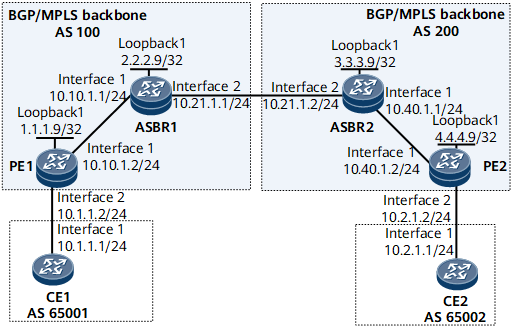
Networking Requirements
On the network shown in Figure 1, CE1 and CE2 belong to the same VPN. CE1 is connected to PE1 in AS 100, and CE2 is connected to PE2 in AS 200.
Inter-AS BGP/MPLS IP VPN is implemented in Option C mode.
Configuration Roadmap
The configuration roadmap is as follows:
Set up an MP-EBGP peer relationship between PEs in different ASs and set the maximum number of hops between the PEs.
Configure the PE and ASBR in the same AS to exchange labeled IPv4 routes.
Configure the local and remote ASBRs to exchange labeled IPv4 routes.
Data Preparation
To complete the configuration, you need the following data:
MPLS LSR IDs of PE1 (1.1.1.9), ASBR1 (2.2.2.9), ASBR2 (3.3.3.9), and PE2 (4.4.4.9)
Name (vpn1), RD (100:1), and export and import VPN targets (1:1) of the VPN instance on each PE
Route-policy parameters to be configured on ASBRs
Procedure
- Configure OSPF on the MPLS backbone networks in AS100 and AS200 so that the PE and ASBR in each AS on each MPLS backbone network can communicate.

The PEs and ASBRs need to advertise their LSR IDs (32-bit IP addresses of loopback interfaces) using OSPF.
# Configure PE1.
[~PE1] ospf
[*PE1-ospf-1] area 0
[*PE1-ospf-1-area-0.0.0.0] network 1.1.1.9 0.0.0.0
[*PE1-ospf-1-area-0.0.0.0] network 10.10.1.0 0.0.0.255
[*PE1-ospf-1-area-0.0.0.0] quit
[*PE1-ospf-1] commit
# Configure ASBR1.
[~ASBR1] ospf
[*ASBR1-ospf-1] area 0
[*ASBR1-ospf-1-area-0.0.0.0] network 2.2.2.9 0.0.0.0
[*ASBR1-ospf-1-area-0.0.0.0] network 10.10.1.0 0.0.0.255
[*ASBR1-ospf-1-area-0.0.0.0] quit
[*ASBR1-ospf-1] commit
The configurations of PE2 and ASBR2 are similar to the configurations of PE1 and ASBR1, respectively. For configuration details, see Configuration Files in this section.
After completing the preceding configurations, run the display ospf peer command on the ASBR and PE in each AS. The command output shows that the OSPF neighbor relationship is in the Full state, which indicates that the OSPF neighbor relationship has been established between the ASBR and PE in the same AS.
The following example uses the command output on PE1.
<PE1> display ospf peer
          OSPF Process 1 with Router ID 1.1.1.9
                  Neighbors
 Area 0.0.0.0 interface 10.10.1.2(GigabitEthernet0/1/0)'s neighbors
 Router ID: 2.2.2.9          Address: 10.10.1.1
   State: Full  Mode:Nbr is Master  Priority: 1
   DR: 2.2.2.9   BDR: 2.2.2.9   MTU: 0
   Dead timer due in 31  sec
   Retrans timer interval: 5
   Neighbor is up for 00:28:11
   Authentication Sequence: [ 0 ]
The ASBR and PE in the same AS can learn the route to each other's Loopback1 address and ping each other.
- Configure basic MPLS capabilities and MPLS LDP on the MPLS backbone networks of AS 100 and AS 200 to establish LDP LSPs.
# Configure PE1.
[~PE1] mpls lsr-id 1.1.1.9
[*PE1] mpls
[*PE1-mpls] quit
[*PE1] mpls ldp
[*PE1-mpls-ldp] quit
[*PE1] interface gigabitethernet 0/1/0
[*PE1-GigabitEthernet0/1/0] mpls
[*PE1-GigabitEthernet0/1/0] mpls ldp
[*PE1-GigabitEthernet0/1/0] quit
[*PE1] commit
# Configure ASBR1.
[~ASBR1] mpls lsr-id 2.2.2.9
[*ASBR1] mpls
[*ASBR1-mpls] quit
[*ASBR1] mpls ldp
[*ASBR1-mpls-ldp] quit
[*ASBR1] interface gigabitethernet 0/1/0
[*ASBR1-GigabitEthernet0/1/0] mpls
[*ASBR1-GigabitEthernet0/1/0] mpls ldp
[*ASBR1-GigabitEthernet0/1/0] quit
[*ASBR1] commit
# Configure ASBR2.
[~ASBR2] mpls lsr-id 3.3.3.9
[*ASBR2] mpls
[*ASBR2-mpls] quit
[*ASBR2] mpls ldp
[*ASBR2-mpls-ldp] quit
[*ASBR2] interface gigabitethernet 0/1/0
[*ASBR2-GigabitEthernet0/1/0] mpls
[*ASBR2-GigabitEthernet0/1/0] mpls ldp
[*ASBR2-GigabitEthernet0/1/0] quit
[*ASBR2] commit
# Configure PE2.
[~PE2] mpls lsr-id 4.4.4.9
[*PE2] mpls
[*PE2-mpls] quit
[*PE2] mpls ldp
[*PE2-mpls-ldp] quit
[*PE2] interface gigabitethernet 0/1/0
[*PE2-GigabitEthernet0/1/0] mpls
[*PE2-GigabitEthernet0/1/0] mpls ldp
[*PE2-GigabitEthernet0/1/0] quit
[*PE2] commit
After completing the preceding configurations, run the display mpls ldp session command. The command output shows that the LDP session status is Operational, which indicates that the LDP sessions have been established between PE1 and the ASBR1, and between PE2 and ASBR2. Then, run the display mpls ldp lsp command. The command output shows that an LDP LSP has been successfully established on each device.
The following example uses the command output on PE1.
[~PE1] display mpls ldp session

 LDP Session(s) in Public Network
 Codes: LAM(Label Advertisement Mode), SsnAge Unit(DDDD:HH:MM)
 An asterisk (*) before a session means the session is being deleted.
 ------------------------------------------------------------------------------
 PeerID             Status      LAM  SsnRole  SsnAge      KASent/Rcv
 ------------------------------------------------------------------------------
 2.2.2.9:0          Operational DU   Passive  0000:00:01  5/5
 ------------------------------------------------------------------------------
 TOTAL: 1 session(s) Found.
[~PE1] display mpls ldp lsp
 LDP LSP Information
 -------------------------------------------------------------------------------
 Flag after Out IF: (I) - RLFA Iterated LSP, (I*) - Normal and RLFA Iterated LSP
 -------------------------------------------------------------------------------
 DestAddress/Mask   In/OutLabel    UpstreamPeer    NextHop          OutInterface
 -------------------------------------------------------------------------------
 1.1.1.9/32         3/NULL         2.2.2.9         127.0.0.1        InLoop0
*1.1.1.9/32         Liberal/1024                   DS/2.2.2.9
 2.2.2.9/32         NULL/3         -               172.16.1.1       GE0/1/0
 2.2.2.9/32         1024/3         2.2.2.9         172.16.1.1       GE0/1/0
 -------------------------------------------------------------------------------
 TOTAL: 3 Normal LSP(s) Found.
 TOTAL: 1 Liberal LSP(s) Found.
 TOTAL: 0 Frr LSP(s) Found.
 An asterisk (*) before an LSP means the LSP is not established
 An asterisk (*) before a Label means the USCB or DSCB is stale
 An asterisk (*) before an UpstreamPeer means the session is stale
 An asterisk (*) before a DS means the session is stale
 An asterisk (*) before a NextHop means the LSP is FRR LSP
- Establish an IBGP peer relationship of the IPv4 address family between the PE and ASBR in each of AS 100 and AS 200.
# Configure PE1.
[~PE1] bgp 100
[*PE1-bgp] peer 2.2.2.9 as-number 100
[*PE1-bgp] peer 2.2.2.9 connect-interface LoopBack1
[*PE1-bgp] commit
# Configure ASBR1.
[~ASBR1] bgp 100
[*ASBR1-bgp] peer 1.1.1.9 as-number 100
[*ASBR1-bgp] peer 1.1.1.9 connect-interface LoopBack1
[*ASBR1-bgp] commit
The configurations of PE2 and ASBR2 are similar to the configurations of PE1 and ASBR1, respectively. For configuration details, see Configuration Files in this section.
- Configure a VPN instance on each PE and bind the VPN instance to the PE's interface directly connected to the CE.
The import route target configured on PE1 must be the same as the export route target configured on PE2; the export route target configured on PE1 must be the same as the import route target configured on PE2.
# Configure PE1.
[~PE1] ip vpn-instance vpn1
[*PE1-vpn-instance-vpn1] route-distinguisher 100:1
[*PE1-vpn-instance-vpn1] vpn-target 1:1 export-extcommunity
[*PE1-vpn-instance-vpn1] vpn-target 1:1 import-extcommunity
[*PE1-vpn-instance-vpn1] quit
[*PE1] interface gigabitethernet 0/1/8
[*PE1-GigabitEthernet0/1/8] ip binding vpn-instance vpn1
[*PE1-GigabitEthernet0/1/8] ip address 10.1.1.2 24
[*PE1-GigabitEthernet0/1/8] quit
[*PE1] commit
# Configure PE2.
[~PE2] ip vpn-instance vpn1
[*PE2-vpn-instance-vpn1] route-distinguisher 200:1
[*PE2-vpn-instance-vpn1] vpn-target 1:1 export-extcommunity
[*PE2-vpn-instance-vpn1] vpn-target 1:1 import-extcommunity
[*PE2-vpn-instance-vpn1] quit
[*PE2] interface gigabitethernet 0/1/8
[*PE2-GigabitEthernet0/1/8] ip binding vpn-instance vpn1
[*PE2-GigabitEthernet0/1/8] ip address 10.2.1.2 24
[*PE2-GigabitEthernet0/1/8] quit
[*PE2] commit
After completing the preceding configuration, run the display ip vpn-instance verbose command on each PE to check VPN instance configurations. In addition, each PE can successfully ping its connected CE.
The following example uses the command output on PE1.
[~PE1] display ip vpn-instance verbose
 Total VPN-Instances configured      : 1
 Total IPv4 VPN-Instances configured : 1
 Total IPv6 VPN-Instances configured : 0

 VPN-Instance Name and ID : vpn1, 1
  Interfaces : GigabitEthernet0/1/8
 Address family ipv4
  Create date : 2012/05/14 07:31:56
  Up time : 0 days, 08 hours, 26 minutes and 31 seconds
  Vrf Status : UP
  Route Distinguisher : 100:1
  Export VPN Targets : 1:1
  Import VPN Targets : 1:1
  Label Policy : label per instance
  Per-Instance Label : 48060
  The diffserv-mode Information is : uniform
  The ttl-mode Information is : pipe
- Configure devices to exchange labeled IPv4 routes.
# On PE1, enable the capability of exchanging labeled IPv4 routes with ASBR1 and advertise the loopback route to ASBR2.
[~PE1] bgp 100
[*PE1-bgp] ipv4-family labeled-unicast
[*PE1-bgp-af-ipv4-labeled] peer 2.2.2.9 enable
[*PE1-bgp-af-ipv4-labeled] network 1.1.1.9 32
[*PE1-bgp] quit
[*PE1] commit
# Configure ASBR1. Enable MPLS on GE 0/1/8 connected to ASBR2.
[~ASBR1] interface gigabitethernet 0/1/8
[*ASBR1-GigabitEthernet0/1/8] ip address 10.21.1.1 24
[*ASBR1-GigabitEthernet0/1/8] mpls
[*ASBR1-GigabitEthernet0/1/8] quit
[*ASBR1] commit
# On ASBR1, enable the capability of exchanging labeled IPv4 routes.
[~ASBR1] bgp 100
[*ASBR1-bgp] ipv4-family labeled-unicast
[*ASBR1-bgp-af-ipv4-labeled] peer 1.1.1.9 enable
[*ASBR1-bgp-af-ipv4-labeled] peer 10.21.1.2 enable
[*ASBR1-bgp] quit
[*ASBR1] commit
The configurations of PE2 and ASBR2 are similar to the configurations of PE1 and ASBR1, respectively. For configuration details, see Configuration Files in this section.
After completing the preceding configuration, run the display bgp labeled routing-table label command on each ASBR. The command output shows label information about BGP routes. After ASBR1 learns the labeled BGP public network routes from ASBR2, ASBR1 automatically allocates labels to the routes and advertises the routes to PE1 that supports the label capability. In this manner, a complete public network LSP can be established.
The following example uses the command output on ASBR1.
[~ASBR1] display bgp labeled routing-table label
 BGP Local router ID is 10.10.1.1
 Status codes: * - valid, > - best, d - damped, x - best external, a - add path,
               h - history,  i - internal, s - suppressed, S - Stale
               Origin : i - IGP, e - EGP, ? - incomplete
Total Number of Routes: 2
        Network           NextHop           In/Out Label
 *>     1.1.1.9           1.1.1.9           48090/48080
 *>     4.4.4.9           10.21.1.2         48091/48095
- Establish an MP-EBGP peer relationship between PE1 and PE2.
# Configure PE1.
[~PE1] bgp 100
[*PE1-bgp] router-id 1.1.1.1
[*PE1-bgp] peer 4.4.4.9 as-number 200
[*PE1-bgp] peer 4.4.4.9 connect-interface LoopBack 1
[*PE1-bgp] peer 4.4.4.9 ebgp-max-hop 10
[*PE1-bgp] import-rib public labeled-unicast
[*PE1-bgp] ipv4-family vpnv4
[*PE1-bgp-af-vpnv4] peer 4.4.4.9 enable
[*PE1-bgp-af-vpnv4] quit
[*PE1-bgp] quit
[*PE1] commit
# Configure PE2.
[~PE2] bgp 200
[*PE2-bgp] router-id 4.4.4.4
[*PE2-bgp] peer 1.1.1.9 as-number 100
[*PE2-bgp] peer 1.1.1.9 connect-interface LoopBack 1
[*PE2-bgp] peer 1.1.1.9 ebgp-max-hop 10
[*PE2-bgp] import-rib public labeled-unicast
[*PE2-bgp] ipv4-family vpnv4
[*PE2-bgp-af-vpnv4] peer 1.1.1.9 enable
[*PE2-bgp-af-vpnv4] quit
[*PE2-bgp] quit
[*PE2] commit
- Verify the configuration.
After the configuration is complete, CE1 and CE2 can learn routes to interfaces on each other and ping each other successfully.
The following example uses the command output on CE1.
[~CE1] display ip routing-table 10.2.1.1 verbose
Route Flags: R - relay, D - download to fib, T - to vpn-instance, B - black hole route
------------------------------------------------------------------------------
Routing Table : _public_
Summary Count : 1

Destination: 10.2.1.0/24
     Protocol: EBGP               Process ID: 0
   Preference: 255                      Cost: 0
      NextHop: 10.1.1.2            Neighbour: 10.1.1.2
        State: Active Adv Relied         Age: 07h11m59s
          Tag: 0                    Priority: low
        Label: NULL                  QoSInfo: 0x0
   IndirectID: 0x10000CC            Instance:
 RelayNextHop: 10.1.1.2            Interface: GigabitEthernet0/1/0
     TunnelID: 0x0                     Flags: RD
[~CE1] ping 10.2.1.1
  PING 10.2.1.1: 56  data bytes, press CTRL_C to break
    Reply from 10.2.1.1: bytes=56 Sequence=1 ttl=252 time=102 ms
    Reply from 10.2.1.1: bytes=56 Sequence=2 ttl=252 time=89 ms
    Reply from 10.2.1.1: bytes=56 Sequence=3 ttl=252 time=106 ms
    Reply from 10.2.1.1: bytes=56 Sequence=4 ttl=252 time=104 ms
    Reply from 10.2.1.1: bytes=56 Sequence=5 ttl=252 time=56 ms
  --- 10.2.1.1 ping statistics ---
    5 packet(s) transmitted
    5 packet(s) received
    0.00% packet loss
    round-trip min/avg/max = 56/91/106 ms
Configuration Files
CE1 configuration file
#
sysname CE1
#
interface GigabitEthernet0/1/0
 undo shutdown
 ip address 10.1.1.1 255.255.255.0
#
bgp 65001
 peer 10.1.1.2 as-number 100
 #
 ipv4-family unicast
  undo synchronization
  import-route direct
  peer 10.1.1.2 enable
#
return
PE1 configuration file
#
sysname PE1
#
ip vpn-instance vpn1
 ipv4-family
  route-distinguisher 100:1
  apply-label per-instance
  vpn-target 1:1 export-extcommunity
  vpn-target 1:1 import-extcommunity
#
mpls lsr-id 1.1.1.9
#
mpls
#
mpls ldp
#
interface GigabitEthernet0/1/0
 undo shutdown
 ip address 10.10.1.2 255.255.255.0
 mpls
 mpls ldp
#
interface GigabitEthernet0/1/8
 undo shutdown
 ip binding vpn-instance vpn1
 ip address 10.1.1.2 255.255.255.0
#
interface LoopBack1
 ip address 1.1.1.9 255.255.255.255
#
bgp 100
 router-id 1.1.1.1
 peer 2.2.2.9 as-number 100
 peer 2.2.2.9 connect-interface LoopBack1
 peer 4.4.4.9 as-number 200
 peer 4.4.4.9 ebgp-max-hop 10
 peer 4.4.4.9 connect-interface LoopBack1
 #
 ipv4-family unicast
  undo synchronization
  import-rib public labeled-unicast
  peer 2.2.2.9 enable
  peer 4.4.4.9 enable
 #
 ipv4-family labeled-unicast
  network 1.1.1.9 255.255.255.255
  peer 2.2.2.9 enable
 #
 ipv4-family vpnv4
  policy vpn-target
  peer 4.4.4.9 enable
 #
 ipv4-family vpn-instance vpn1
  peer 10.1.1.1 as-number 65001
  import-route direct
#
ospf 1
 area 0.0.0.0
  network 1.1.1.9 0.0.0.0
  network 10.10.1.0 0.0.0.255
#
return
ASBR1 configuration file
#
sysname ASBR1
#
mpls lsr-id 2.2.2.9
#
mpls
#
mpls ldp
#
interface GigabitEthernet0/1/0
 undo shutdown
 ip address 10.10.1.1 255.255.255.0
 mpls
 mpls ldp
#
interface GigabitEthernet0/1/8
 undo shutdown
 ip address 10.21.1.1 255.255.255.0
 mpls
#
interface LoopBack1
 ip address 2.2.2.9 255.255.255.255
#
bgp 100
 peer 1.1.1.9 as-number 100
 peer 1.1.1.9 connect-interface LoopBack1
 peer 10.21.1.2 as-number 200
 #
 ipv4-family unicast
  undo synchronization
  peer 1.1.1.9 enable
  peer 10.21.1.2 enable
 #
 ipv4-family labeled-unicast
  peer 1.1.1.9 enable
  peer 10.21.1.2 enable
#
ospf 1
 area 0.0.0.0
  network 2.2.2.9 0.0.0.0
  network 10.10.1.0 0.0.0.255
#
return
ASBR2 configuration file
#
sysname ASBR2
#
mpls lsr-id 3.3.3.9
#
mpls
#
mpls ldp
#
interface GigabitEthernet0/1/0
 undo shutdown
 ip address 10.40.1.1 255.255.255.0
 mpls
 mpls ldp
#
interface GigabitEthernet0/1/8
 undo shutdown
 ip address 10.21.1.2 255.255.255.0
 mpls
#
interface LoopBack1
 ip address 3.3.3.9 255.255.255.255
#
bgp 200
 peer 4.4.4.9 as-number 200
 peer 4.4.4.9 connect-interface LoopBack1
 peer 10.21.1.1 as-number 100
 #
 ipv4-family unicast
  undo synchronization
  peer 4.4.4.9 enable
  peer 10.21.1.1 enable
 #
 ipv4-family labeled-unicast
  peer 4.4.4.9 enable
  peer 10.21.1.1 enable
#
ospf 1
 area 0.0.0.0
  network 3.3.3.9 0.0.0.0
  network 10.40.1.0 0.0.0.255
#
return
PE2 configuration file
#
sysname PE2
#
ip vpn-instance vpn1
 ipv4-family
  route-distinguisher 200:1
  apply-label per-instance
  vpn-target 1:1 export-extcommunity
  vpn-target 1:1 import-extcommunity
#
mpls lsr-id 4.4.4.9
#
mpls
#
mpls ldp
#
interface GigabitEthernet0/1/0
 undo shutdown
 ip address 10.40.1.2 255.255.255.0
 mpls
 mpls ldp
#
interface GigabitEthernet0/1/8
 undo shutdown
 ip binding vpn-instance vpn1
 ip address 10.2.1.2 255.255.255.0
#
interface LoopBack1
 ip address 4.4.4.9 255.255.255.255
#
bgp 200
 router-id 4.4.4.4
 peer 1.1.1.9 as-number 100
 peer 1.1.1.9 ebgp-max-hop 10
 peer 1.1.1.9 connect-interface LoopBack1
 peer 3.3.3.9 as-number 200
 peer 3.3.3.9 connect-interface LoopBack1
 #
 ipv4-family unicast
  undo synchronization
  import-rib public labeled-unicast
  peer 1.1.1.9 enable
  peer 3.3.3.9 enable
 #
 ipv4-family labeled-unicast
  network 4.4.4.9 255.255.255.255
 peer 3.3.3.9 enable
 #
 ipv4-family vpnv4
  policy vpn-target
  peer 1.1.1.9 enable
 #
 ipv4-family vpn-instance vpn1
  peer 10.2.1.1 as-number 65002
  import-route direct
#
ospf 1
 area 0.0.0.0
  network 4.4.4.9 0.0.0.0
  network 10.40.1.0 0.0.0.255
#
return
CE2 configuration file
#
sysname CE2
#
interface GigabitEthernet0/1/0
 undo shutdown
 ip address 10.2.1.1 255.255.255.0
#
bgp 65002
 peer 10.2.1.2 as-number 200
 #
 ipv4-family unicast
  undo synchronization
  import-route direct
  peer 10.2.1.2 enable
#
return