Example for Configuring VPN ORF
This section provides an example for configuring VPN ORF, which helps reduce the number of unwanted routes to be sent and improve bandwidth utilization.
Networking Requirements
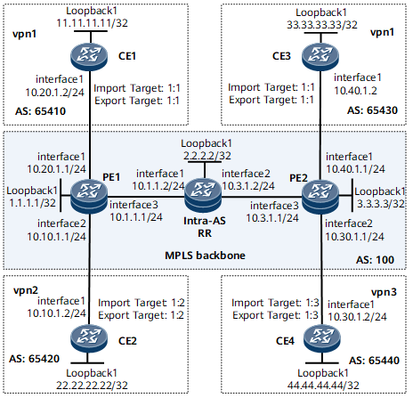
CE1 and CE3 belong to vpn1, CE2 belongs to vpn2, and CE4 belongs to vpn3.
The VPN targets used by vpn1, vpn2, and vpn3 are 1:1, 1:2, and 1:3, respectively.
In the BGP-VPN-Target address family view, VPN ORF route-based peer relationships are established between the RR and PE1 and between the RR and PE2. These relationships enable the peers to negotiate the VPN ORF capability with each other. The RR learns the routes matching the ERTs 1:1 and 1:2 from PE1 and the routes matching the ERTs 1:1 and 1:3 from PE2. Because PE1 and PE2 require the same IRT, the RR sends only the routes with the IRT 1:1 to PE1 and PE2.
Precautions
When you configure VPN ORF, note the following:
On the same VPN, the export VPN target list of a site shares VPN targets with the import VPN target lists of the other sites. Conversely, the import VPN target list of a site shares VPN targets with the export VPN target lists of the other sites.
After a PE interface connected to a CE is bound to a VPN instance, Layer 3 features, such as the IP address and routing protocol, on this interface are automatically deleted. These features can be reconfigured if required.
Configuration Roadmap
The configuration roadmap is as follows:
Configure OSPF on the backbone network to implement interworking, configure basic MPLS functions and MPLS LDP, and set up MPLS LSPs. (The RR in this example also functions as a P node.)
Set up BGP-VPNv4 peer relationships between PE1 and the RR, and between PE2 and the RR. Configure VPN instances on each PE, and bind each PE interface that is connected to a CE to a specific VPN instance.
Configure PE1 to import routes from CE1, and configure CE2 and PE2 to import routes from CE3 and CE4.
Establish VPN ORF route-based peer relationships between the RR and PE1 and between the RR and PE2 in the BGP-VPN-Target (VT) address family view, and enable the VPN ORF function.
Data Preparation
To complete the configuration, you need the following data:
Router IDs of PE1, RR, and PE2 (1.1.1.1, 2.2.2.2, and 3.3.3.3, respectively); AS number (100)
RDs of vpn1, vpn2, and vpn3
IRTs and ERTs of vpn1, vpn2, and vpn3
Procedure
- Configure an IGP on the MPLS backbone network to implement connectivity between the devices on the backbone network.
This example uses OSPF as the IGP. For configuration details, see Configuration Files in this section.

The IP addresses of loopback interfaces that are used as LSR IDs need to be advertised.
After the configuration is complete, the devices along an LSP can learn the address of the loopback interface from each other.
- Configure basic MPLS functions, enable MPLS LDP, and establish LDP LSPs on the MPLS backbone network.
# Configure PE1.
[~PE1] mpls lsr-id 1.1.1.1
[*PE1] mpls
[*PE1-mpls] quit
[*PE1] mpls ldp
[*PE1-mpls-ldp] commit
[~PE1-mpls-ldp] quit
[*PE1] interface gigabitethernet 0/1/16
[*PE1-GigabitEthernet0/1/16] mpls
[*PE1-GigabitEthernet0/1/16] mpls ldp
[*PE1-GigabitEthernet0/1/16] commit
[~PE1-GigabitEthernet0/1/16] quit
# Configure the RR.
[~RR] mpls lsr-id 2.2.2.2
[*RR] mpls
[*RR-mpls] quit
[*RR] mpls ldp
[*RR-mpls-ldp] commit
[~RR-mpls-ldp] quit
[*RR] interface gigabitethernet 0/1/0
[*RR-GigabitEthernet0/1/0] mpls
[*RR-GigabitEthernet0/1/0] mpls ldp
[*RR-GigabitEthernet0/1/0] quit
[*RR] interface gigabitethernet 0/1/8
[*RR-GigabitEthernet0/1/8] mpls
[*RR-GigabitEthernet0/1/8] mpls ldp
[*RR-GigabitEthernet0/1/8] commit
[~RR-GigabitEthernet0/1/8] quit
# Configure PE2.
[~PE2] mpls lsr-id 3.3.3.3
[*PE2] mpls
[*PE2-mpls] quit
[*PE2] mpls ldp
[*PE2-mpls-ldp] commit
[~PE2-mpls-ldp] quit
[*PE2] interface gigabitethernet 0/1/16
[*PE2-GigabitEthernet0/1/16] mpls
[*PE2-GigabitEthernet0/1/16] mpls ldp
[*PE2-GigabitEthernet0/1/16] commit
[~PE2-GigabitEthernet0/1/16] quit
After the configuration is complete, LDP sessions are set up between PE1 and the RR and between the RR and PE2. Run the display mpls ldp session command on any of the devices. The command output shows that the LDP session status is Operational. Run the display mpls ldp lsp command. The command output shows that LDP LSPs are set up.
- On each PE, create a VPN instance, enable the IPv4 address family in the instance, and bind the interface connected to a CE to the VPN instance.
# Configure PE1.
[~PE1] ip vpn-instance vpn1
[*PE1-vpn-instance-vpn1] ipv4-family
[*PE1-vpn-instance-vpn1-af-ipv4] route-distinguisher 100:1
[*PE1-vpn-instance-vpn1-af-ipv4] vpn-target 1:1 both
[*PE1-vpn-instance-vpn1-af-ipv4] quit
[*PE1-vpn-instance-vpn1] quit
[*PE1] ip vpn-instance vpn2
[*PE1-vpn-instance-vpn2] ipv4-family
[*PE1-vpn-instance-vpn2-af-ipv4] route-distinguisher 100:2
[*PE1-vpn-instance-vpn2-af-ipv4] vpn-target 1:2 both
[*PE1-vpn-instance-vpn2-af-ipv4] quit
[*PE1-vpn-instance-vpn2] quit
[*PE1] interface gigabitethernet 0/1/0
[*PE1-GigabitEthernet0/1/0] ip binding vpn-instance vpn1
[*PE1-GigabitEthernet0/1/0] ip address 10.20.1.1 24
[*PE1-GigabitEthernet0/1/0] quit
[*PE1] interface gigabitethernet 0/1/8
[*PE1-GigabitEthernet0/1/8] ip binding vpn-instance vpn2
[*PE1-GigabitEthernet0/1/8] ip address 10.10.1.1 24
[*PE1-GigabitEthernet0/1/8] quit
[*PE1] commit
# Configure PE2.
[~PE2] ip vpn-instance vpn1
[*PE2-vpn-instance-vpn1] ipv4-family
[*PE2-vpn-instance-vpn1-af-ipv4] route-distinguisher 200:1
[*PE2-vpn-instance-vpn1-af-ipv4] vpn-target 1:1 both
[*PE2-vpn-instance-vpn1-af-ipv4] quit
[*PE2-vpn-instance-vpn1] quit
[*PE2] ip vpn-instance vpn3
[*PE2-vpn-instance-vpn3] ipv4-family
[*PE2-vpn-instance-vpn3-af-ipv4] route-distinguisher 200:2
[*PE2-vpn-instance-vpn3-af-ipv4] vpn-target 1:3 both
[*PE2-vpn-instance-vpn3-af-ipv4] quit
[*PE2-vpn-instance-vpn3] quit
[*PE2] interface gigabitethernet 0/1/0
[*PE2-GigabitEthernet0/1/0] ip binding vpn-instance vpn1
[*PE2-GigabitEthernet0/1/0] ip address 10.40.1.1 24
[*PE2-GigabitEthernet0/1/0] quit
[*PE2] interface gigabitethernet 0/1/8
[*PE2-GigabitEthernet0/1/8] ip binding vpn-instance vpn3
[*PE2-GigabitEthernet0/1/8] ip address 10.30.1.1 24
[*PE2-GigabitEthernet0/1/8] commit
[*PE2-GigabitEthernet0/1/8] quit
[*PE2] commit
# Assign an IP address to each CE interface as shown in Figure 1. For details, see Configuration Files in this section.
After the configuration is complete, run the display ip vpn-instance verbose command on each PE. The command output shows the configurations of VPN instances. Each PE can successfully ping its connected CEs.
If a PE has multiple interfaces bound to the same VPN instance, specify a source IP address in the ping -vpn-instance vpn-instance-name -a source-ip-address dest-ip-address command to ping the CE that is connected to the remote PE. If the source IP address is not specified, the ping operation fails.
- Set up EBGP peer relationships between the PEs and CEs.
# Configure CE1.
[~CE1] interface loopback 1
[*CE1-LoopBack1] ip address 11.11.11.11 32
[*CE1-LoopBack1] quit
[*CE1] bgp 65410
[*CE1-bgp] peer 10.20.1.1 as-number 100
[*CE1-bgp] network 11.11.11.11 32
[*CE1-bgp] quit
[*CE1] commit
The configurations of CE2, CE3, and CE4 are similar to the configuration of CE1. For configuration details, see Configuration Files in this section.
# Configure PE1.
[~PE1] bgp 100
[*PE1-bgp] ipv4-family vpn-instance vpn1
[*PE1-bgp-vpn1] peer 10.20.1.2 as-number 65410
[*PE1-bgp-vpn1] quit
[*PE1-bgp] ipv4-family vpn-instance vpn2
[*PE1-bgp-vpn2] peer 10.10.1.2 as-number 65420
[*PE1-bgp-vpn2] commit
[~PE1-bgp-vpn2] quit
[~PE1-bgp] quit
The configuration of PE2 is similar to the configuration of PE1. For configuration details, see Configuration Files in this section.
After the configuration is complete, run the display bgp vpnv4 vpn-instance peer command on each PE. The command output shows that BGP peer relationships between PEs and CEs have been established and are in the Established state.
Take the peer relationship between PE1 and CE1 as an example:
[~PE1] display bgp vpnv4 vpn-instance vpn1 peer BGP local router ID : 1.1.1.1 Local AS number : 100 Total number of peers : 1 Peers in established state : 1 Peer V AS MsgRcvd MsgSent OutQ Up/Down State PrefRcv 10.20.1.2 4 65410 11 9 0 00:06:37 Established 1 - Establish MP-IBGP peer relationships between the PEs and RR.
# Configure PE1.
[~PE1] bgp 100
[~PE1-bgp] peer 2.2.2.2 as-number 100
[*PE1-bgp] peer 2.2.2.2 connect-interface loopback 1
[*PE1-bgp] ipv4-family vpnv4
[*PE1-bgp-af-vpnv4] peer 2.2.2.2 enable
[*PE1-bgp-af-vpnv4] commit
[~PE1-bgp-af-vpnv4] quit
[~PE1-bgp] quit
# Configure PE2.
[~PE2] bgp 100
[~PE2-bgp] peer 2.2.2.2 as-number 100
[*PE2-bgp] peer 2.2.2.2 connect-interface loopback 1
[*PE2-bgp] ipv4-family vpnv4
[*PE2-bgp-af-vpnv4] peer 2.2.2.2 enable
[*PE2-bgp-af-vpnv4] commit
[~PE2-bgp-af-vpnv4] quit
[~PE2-bgp] quit
# Configure the RR.
[~RR] bgp 100
[~RR-bgp] peer 1.1.1.1 as-number 100
[*RR-bgp] peer 1.1.1.1 connect-interface loopback 1
[~RR-bgp] peer 3.3.3.3 as-number 100
[*RR-bgp] peer 3.3.3.3 connect-interface loopback 1
[*RR-bgp] ipv4-family vpnv4
[*RR-bgp-af-vpnv4] peer 1.1.1.1 enable
[*RR-bgp-af-vpnv4] peer 3.3.3.3 enable
[*RR-bgp-af-vpnv4] commit
[~RR-bgp-af-vpnv4] quit
[~RR-bgp] quit
After the configuration is complete, run the display bgp peer or display bgp vpnv4 all peer command on the RR. The command output shows that BGP peer relationships have been set up between the PEs and RR and are in the Established state.
[~RR] display bgp peer BGP local router ID : 2.2.2.2 Local AS number : 100 Total number of peers : 2 Peers in established state : 2 Peer V AS MsgRcvd MsgSent OutQ Up/Down State PrefRcv 1.1.1.1 4 100 2 6 0 00:00:12 Established 0 3.3.3.3 4 100 2 6 0 00:00:12 Established 0 - Establish VPN ORF route-based peer relationships between the RR and PE1 and between the RR and PE2 in the BGP-VT address family view, and enable the VPN ORF function.
# Configure PE1.
[~PE1] bgp 100
[~PE1-bgp] ipv4-family vpn-target
[*PE1-bgp-af-vpn-target] peer 2.2.2.2 enable
[*PE1-bgp-af-vpn-target] commit
[~PE1-bgp-af-vpn-target] quit
[~PE1-bgp] quit
# Configure PE2.
[~PE2] bgp 100
[*PE2-bgp] ipv4-family vpn-target
[*PE2-bgp-af-vpn-target] peer 2.2.2.2 enable
[*PE2-bgp-af-vpn-target] commit
[~PE2-bgp-af-vpn-target] quit
[~PE2-bgp] quit
# Configure the RR.
[~RR] bgp 100
[*RR-bgp] ipv4-family vpnv4
[*RR-bgp-af-vpnv4] peer 1.1.1.1 reflect-client
[*RR-bgp-af-vpnv4] peer 3.3.3.3 reflect-client
[*RR-bgp-af-vpnv4] quit
[*RR-bgp] ipv4-family vpn-target
[*RR-bgp-af-vpn-target] peer 1.1.1.1 enable
[*RR-bgp-af-vpn-target] peer 1.1.1.1 reflect-client
[*RR-bgp-af-vpn-target] peer 3.3.3.3 enable
[*RR-bgp-af-vpn-target] peer 3.3.3.3 reflect-client
[*RR-bgp-af-vpn-target] commit
[~RR-bgp-af-vpn-target] quit
[~RR-bgp] quit
- Verify the configuration.
Run the display bgp vpn-target routing-table command on each PE. The command output shows routes in the BGP-VT address family.
The following example uses the command output on PE1:
[~PE1] display bgp vpn-target routing-table
 Total number of routes from all PE: 2

 BGP Local router ID is 1.1.1.1
 Status codes: * - valid, > - best, d - damped, x - best external, a - add path,
               h - history,  i - internal, s - suppressed, S - Stale
               Origin : i - IGP, e - EGP, ? - incomplete


 Origin AS: 100

 Total Number of Routes: 5
        Network            NextHop        MED        LocPrf    PrefVal Path/Ogn
 *>     RT <1 : 1>         0.0.0.0         0                     0       ?
 * i                       2.2.2.2         0          100        0       ?
 *>     RT <1 : 2>         0.0.0.0         0                     0       ?
 * i                       2.2.2.2         0          100        0       ?
 *>i    RT <1 : 3>         3.3.3.3         0          100        0       ?
On the RR, check the VPNv4 routes sent to PE1. The RR receives the routes that match the VPN targets 1:1 and 1:3 from PE2 and advertises only the route with the VPN target 1:1 to PE1.
[~RR] display bgp vpnv4 all routing-table peer 1.1.1.1 advertised-routes
BGP Local router ID is 2.2.2.2 Status codes: * - valid, > - best, d - damped, x - best external, a - add path, h - history, i - internal, s - suppressed, S - Stale Origin : i - IGP, e - EGP, ? - incomplete RPKI validation codes: V - valid, I - invalid, N - not-found Total Number of Routes: 1 Route Distinguisher: 200:1 Network NextHop MED LocPrf PrefVal Path/Ogn *>i 33.33.33.33/32 3.3.3.3 0 100 0 65440i
Configuration Files
PE1 configuration file
#
sysname PE1
#
ip vpn-instance vpn1
 ipv4-family
  route-distinguisher 100:1
  apply-label per-instance
  vpn-target 1:1 export-extcommunity
  vpn-target 1:1 import-extcommunity
#
ip vpn-instance vpn2
 ipv4-family
  route-distinguisher 100:2
  apply-label per-instance
  vpn-target 1:2 export-extcommunity
  vpn-target 1:2 import-extcommunity
#
mpls lsr-id 1.1.1.1
#
mpls
#
mpls ldp
 #
 ipv4-family
#
interface GigabitEthernet0/1/0
 undo shutdown
 ip binding vpn-instance vpn1
 ip address 10.20.1.1 255.255.255.0
#
interface GigabitEthernet0/1/8
 undo shutdown
 ip binding vpn-instance vpn2
 ip address 10.10.1.1 255.255.255.0
#
interface GigabitEthernet0/1/16
 undo shutdown
 ip address 10.1.1.1 255.255.255.0
 mpls
 mpls ldp
#
interface LoopBack1
 ip address 1.1.1.1 255.255.255.255
#
bgp 100
 peer 2.2.2.2 as-number 100
 peer 2.2.2.2 connect-interface LoopBack1
 #
 ipv4-family unicast
  undo synchronization
  undo synchronization
  peer 2.2.2.2 enable
 #
 ipv4-family vpnv4
  undo policy vpn-target
  peer 2.2.2.2 enable
 #
 ipv4-family vpn-instance vpn1
  peer 10.20.1.2 as-number 65410
 #
 ipv4-family vpn-instance vpn2
  peer 10.10.1.2 as-number 65420
 #
 ipv4-family vpn-target
  peer 2.2.2.2 enable
#
ospf 1
 area 0.0.0.0
  network 1.1.1.1 0.0.0.0
  network 10.1.1.0 0.0.0.255
#
return
RR configuration file
#
sysname RR
#
mpls lsr-id 2.2.2.2
#
mpls
#
mpls ldp
 #
 ipv4-family
#
interface GigabitEthernet0/1/0
 undo shutdown
 ip address 10.1.1.2 255.255.255.0
 mpls
 mpls ldp
#
interface GigabitEthernet0/1/8
 undo shutdown
 ip address 10.3.1.2 255.255.255.0
 mpls
 mpls ldp
#
interface LoopBack1
 ip address 2.2.2.2 255.255.255.255
#
bgp 100
 peer 1.1.1.1 as-number 100
 peer 1.1.1.1 connect-interface LoopBack1
 peer 3.3.3.3 as-number 100
 peer 3.3.3.3 connect-interface LoopBack1
 #
 ipv4-family unicast
  undo synchronization
  undo synchronization
  peer 1.1.1.1 enable
  undo synchronization
  peer 3.3.3.3 enable
 #
 ipv4-family vpnv4
  undo policy vpn-target
  peer 1.1.1.1 enable
  peer 1.1.1.1 reflect-client
  peer 3.3.3.3 enable
  peer 3.3.3.3 reflect-client
 #
 ipv4-family vpn-target
  peer 1.1.1.1 enable
  peer 1.1.1.1 reflect-client
  peer 3.3.3.3 enable
  peer 3.3.3.3 reflect-client
#
ospf 1
 area 0.0.0.0
  network 2.2.2.2 0.0.0.0
  network 10.1.1.0 0.0.0.255
  network 10.3.1.0 0.0.0.255
#
return
PE2 configuration file
#
sysname PE2
#
ip vpn-instance vpn1
 ipv4-family
  route-distinguisher 200:1
  apply-label per-instance
  vpn-target 1:1 export-extcommunity
  vpn-target 1:1 import-extcommunity
#
ip vpn-instance vpn3
 ipv4-family
  route-distinguisher 200:2
  apply-label per-instance
  vpn-target 1:3 export-extcommunity
  vpn-target 1:3 import-extcommunity
#
mpls lsr-id 3.3.3.3
#
mpls
#
mpls ldp
 #
 ipv4-family
#
interface GigabitEthernet0/1/0
 undo shutdown
 ip binding vpn-instance vpn1
 ip address 10.40.1.1 255.255.255.0
#
interface GigabitEthernet0/1/8
 undo shutdown
 ip binding vpn-instance vpn3
 ip address 10.30.1.1 255.255.255.0
#
interface GigabitEthernet0/1/16
 undo shutdown
 ip address 10.3.1.1 255.255.255.0
 mpls
 mpls ldp
#
interface LoopBack1
 ip address 3.3.3.3 255.255.255.255
#
bgp 100
 peer 2.2.2.2 as-number 100
 peer 2.2.2.2 connect-interface LoopBack1
 #
 ipv4-family unicast
  undo synchronization
  undo synchronization
  peer 2.2.2.2 enable
 #
 ipv4-family vpnv4
  undo policy vpn-target
  peer 2.2.2.2 enable
 #
 ipv4-family vpn-instance vpn1
  peer 10.40.1.2 as-number 65430
 #
 ipv4-family vpn-instance vpn3
  peer 10.30.1.2 as-number 65440
 #
 ipv4-family vpn-target
  peer 2.2.2.2 enable
#
ospf 1
 area 0.0.0.0
  network 3.3.3.3 0.0.0.0
  network 10.3.1.0 0.0.0.255
#
return
CE1 configuration file
#
sysname CE1
#
interface GigabitEthernet0/1/0
 undo shutdown
 ip address 10.20.1.2 255.255.255.0
#
interface LoopBack1
 ip address 11.11.11.11 255.255.255.255
#
bgp 65410
 peer 10.20.1.1 as-number 100
 #
 ipv4-family unicast
  undo synchronization
  network 11.11.11.11 255.255.255.255
  undo synchronization
  peer 10.20.1.1 enable
#
return
CE2 configuration file
#
sysname CE2
#
interface GigabitEthernet0/1/0
 undo shutdown
 ip address 10.10.1.2 255.255.255.0
#
interface LoopBack1
 ip address 22.22.22.22 255.255.255.255
#
bgp 65420
 peer 10.10.1.1 as-number 100
 #
 ipv4-family unicast
  undo synchronization
  network 22.22.22.22 255.255.255.255
  undo synchronization
  peer 10.10.1.1 enable
#
return
CE3 configuration file
#
sysname CE3
#
interface GigabitEthernet0/1/0
 undo shutdown
 ip address 10.40.1.2 255.255.255.0
#
interface LoopBack1
 ip address 33.33.33.33 255.255.255.255
#
bgp 65430
 peer 10.40.1.1 as-number 100
 #
 ipv4-family unicast
  undo synchronization
  network 33.33.33.33 255.255.255.255
  undo synchronization
  peer 10.40.1.1 enable
#
return
CE4 configuration file
#
sysname CE4
#
interface GigabitEthernet0/1/0
 undo shutdown
 ip address 10.30.1.2 255.255.255.0
#
interface LoopBack1
 ip address 44.44.44.44 255.255.255.255
#
bgp 65440
 peer 10.30.1.1 as-number 100
 #
 ipv4-family unicast
  undo synchronization
  network 44.44.44.44 255.255.255.255
  undo synchronization
  peer 10.30.1.1 enable
#
return