Example for Configuring Carrier's Carrier Solution 2 (BGP Label Distribution)
This section provides an example for configuring the inter-AS carrier's carrier in the scenario where a Level 1 carrier and Level 2 carriers belong to different ASs. After this configuration, the Level 2 carriers can provide BGP/MPLS IP VPN services.
Networking Requirements
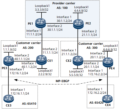
As shown in Figure 1, the Level 1 carrier and Level 2 carriers are in the different ASs, and the Level 2 carriers provide BGP/MPLS IP VPN services for its clients.
The difference between the configuration example in this section and the configuration example in the previous section is that Level 2 carriers and the Level 1 carrier do not belong to the same AS in this section.
Deployment Roadmap
The configuration roadmap is as follows:
The two types of routes are exchanged as follows:
Exchange of the internal routes of the Level 2 carrier on the backbone network of Level 1 carrier: Configure the Level 2 carrier to access the Level 1 carrier as the Level 1 carrier CE.
Exchange of the external routes of the Level 2 carrier between Level 2 carrier PEs: Set up an MP-EBGP peer relationship between Level 2 carrier PEs (PE3 and PE4).
Configure carrier's carrier across different ASs. Because the Level 1 carrier PEs (PE1 and PE2) reside in a different AS from the Level 1 carrier CEs (CE1 and CE2), the PEs need to establish labeled MP-EBGP relationships with the CEs so that the PEs and CEs can exchange labeled routes.
Data Preparation
To complete the configuration, you need the following data:
MPLS LSR IDs of the Level 1 carrier PE and the Level 2 carrier PE and CE
Data required for configuring an IGP
Name, RD, and VPN target of the VPN instance created on the PEs
Two route-policies on the Level 1 carrier CEs
Procedure
- Configure BGP/MPLS IP VPN on the Level 1 carrier backbone network and configure IS-IS as an IGP of the backbone network. Enable LDP between PE1 and PE2, and establish an MP-IBGP peer relationship.
For the configuration procedure, see Example for Configuring Carrier's Carrier Solution 1 (LDP Multi-Instance).

During the IGP configuration, the 32-bit Loopback interface address of each PE needs to be advertised.
- Configure the Level 2 carrier's network. Use OSPF as an IGP. Enable LDP between the PE3 and the CE1, and between the PE4 and the CE2, respectively.
For the configuration procedure, see Example for Configuring Carrier's Carrier Solution 1 (LDP Multi-Instance).
During the IGP configuration, the 32-bit Loopback interface address of each PE and CE needs to be advertised.
- Configure the Level 1 carrier CE to access the Level 1 carrier PE. Configure the exchange of labeled IPv4 routes between them.
# Configure CE1 to exchange labeled IPv4 routes with PE1 and PE3.
<~CE1> system-view
[~CE1] interface gigabitethernet 0/1/8
[*CE1-Gigabitethernet0/1/8] ip address 11.1.1.1 24
[*CE1-Gigabitethernet0/1/8] mpls
[*CE1-Gigabitethernet0/1/8] quit
[*CE1] route-policy policy1 permit node 1
[*CE1-route-policy] apply mpls-label
[*CE1-route-policy] quit
[*CE1] route-policy policy2 permit node 1
[*CE1-route-policy] if-match mpls-label
[*CE1-route-policy] apply mpls-label
[*CE1-route-policy] quit
[*CE1] bgp 200
[*CE1-bgp] peer 1.1.1.9 as-number 200
[*CE1-bgp] peer 1.1.1.9 connect-interface loopback 1
[*CE1-bgp] peer 1.1.1.9 route-policy policy2 export
[*CE1-bgp] peer 1.1.1.9 label-route-capability
*[CE1-bgp] peer 11.1.1.2 as-number 100
[*CE1-bgp] peer 11.1.1.2 route-policy policy1 export
[*CE1-bgp] peer 11.1.1.2 label-route-capability
[*CE1-bgp] import-route ospf 1
[*CE1-bgp] commit
[~CE1-bgp] quit
# Configure PE1 to exchange labeled IPv4 routes with CE1.
To ensure normal forwarding, configure only the per-route per-label mode in a VPN instance.
<~PE1> system-view
[~PE1] ip vpn-instance vpn1
[*PE1-vpn-instance-vpn1] ipv4-family
[*PE1-vpn-instance-vpn1-af-ipv4] route-distinguisher 200:1
[*PE1-vpn-instance-vpn1-af-ipv4] apply-label per-route
[*PE1-vpn-instance-vpn1-af-ipv4] vpn-target 1:1 both
[*PE1-vpn-instance-vpn1-af-ipv4] quit
[*PE1-vpn-instance-vpn1] quit
[*PE1] interface gigabitethernet 0/1/0
[*PE1-Gigabitethernet0/1/0] ip binding vpn-instance vpn1
[*PE1-Gigabitethernet0/1/0] ip address 11.1.1.2 24
[*PE1-Gigabitethernet0/1/0] mpls
[*PE1-Gigabitethernet0/1/0] quit
[*PE1] route-policy policy1 permit node 1
[*PE1-route-policy] apply mpls-label
[*PE1-route-policy] quit
[*PE1] bgp 100
[*PE1-bgp] ipv4-family vpn-instance vpn1
[*PE1-bgp-vpn1] peer 11.1.1.1 as-number 200
[*PE1-bgp-vpn1] peer 11.1.1.1 route-policy policy1 export
[*PE1-bgp-vpn1] peer 11.1.1.1 label-route-capability
[*PE1-bgp-vpn1] commit
[~PE1-bgp-vpn1] quit
[~PE1-bgp] quit
# Configure PE3 to exchange labeled IPv4 routes with CE1.
<~PE3> system-view
[~PE3] bgp 200
[*PE3-bgp] peer 2.2.2.9 as-number 200
[*PE3-bgp] peer 2.2.2.9 connect-interface loopback 1
[*PE3-bgp] peer 2.2.2.9 label-route-capability
[*PE3-bgp] commit
[~PE3-bgp] quit
After the configuration, a BGP peer relationship has been established between CE1 and PE3, and between CE1 and PE1.
[~CE1] display bgp peer
 BGP local router ID : 2.2.2.9
 Local AS number : 200
 Total number of peers : 2               Peers in established state : 2
  Peer       V   AS  MsgRcvd  MsgSent  OutQ  Up/Down       State  PrefRcv
  1.1.1.9    4  200        7        8     0 00:04:07 Established       0
  11.1.1.2   4  100        3        4     0 00:00:08 Established       0
The configurations of PE4, CE2, and PE2 are similar to those of PE3, CE1, and PE1, respectively. For configuration details, see Configuration Files in this section.
- Configure the Level 2 carrier's customers to access the Level 2 carrier PE.
For the detailed configuration procedure, see Example for Configuring Carrier's Carrier Solution 1 (LDP Multi-Instance).
- Establish an MP-EBGP peer relationship between the Level 2 carrier PEs to exchange VPN routes of the Level 2 carrier's customers.
# Configure PE3.
<~PE3> system-view
[~PE3] bgp 200
[*PE3-bgp] peer 6.6.6.9 as-number 300
[*PE3-bgp] peer 6.6.6.9 connect-interface loopback 1
[*PE3-bgp] peer 6.6.6.9 ebgp-max-hop 10
[*PE3-bgp] ipv4-family vpnv4
[*PE3-bgp-af-vpnv4] peer 6.6.6.9 enable
[*PE3-bgp-af-vpnv4] commit
[~PE3-bgp-af-vpnv4] quit
[~PE3-bgp] quit
# Configure PE4.
<~PE4> system-view
[~PE4] bgp 300
[*PE4-bgp] peer 1.1.1.9 as-number 200
[*PE4-bgp] peer 1.1.1.9 connect-interface loopback 1
[*PE4-bgp] peer 1.1.1.9 ebgp-max-hop 10
[*PE4-bgp] ipv4-family vpnv4
[*PE4-bgp-af-vpnv4] peer 1.1.1.9 enable
[*PE4-bgp-af-vpnv4] commit
[~PE4-bgp-af-vpnv4] quit
[~PE4-bgp] quit
- Verify the configuration.
After completing the configuration, run the display ip routing-table command on PE1 and PE2. The command output shows that only routes from the Level 1 carrier's network exist in the public routing tables on PE1 and PE2. The following example uses the command output on PE1.
[~PE1] display ip routing-table
Route Flags: R - relay, D - download to fib, T - to vpn-instance, B - black hole route
------------------------------------------------------------------------------
Routing Table: Public
         Destinations : 7        Routes : 7
  Destination/Mask  Proto  Pre  Cost      Flags   NextHop        Interface
        3.3.3.9/32  Direct 0    0             D  127.0.0.1       InLoopBack0
        4.4.4.9/32  ISIS   15   10            D  30.1.1.2        Gigabitethernet0/1/8
       30.1.1.0/24  Direct 0    0             D  30.1.1.1        Gigabitethernet0/1/8
       30.1.1.1/32  Direct 0    0             D  127.0.0.1       InLoopBack0
       30.1.1.2/32  Direct 0    0             D  30.1.1.2        Gigabitethernet0/1/8
      127.0.0.0/8   Direct 0    0             D  127.0.0.1       InLoopBack0
      127.0.0.1/32  Direct 0    0             D  127.0.0.1       InLoopBack0
Run the display ip routing-table vpn-instance command on PE1 and PE2. The command output shows that the Level 2 carriers' internal routes instead of the Level 2 carriers' external routes exist in the VPN instances of PE1 and PE2. The following example uses the command output on PE1.
[~PE1] display ip routing-table vpn-instance vpn1
Route Flags: R - relay, D - download to fib, T - to vpn-instance, B - black hole route
------------------------------------------------------------------------------
Routing Table: vpn1
         Destinations : 11       Routes : 11
Destination/Mask  Proto  Pre  Cost        Flags  NextHop         Interface
      1.1.1.9/32  EBGP   255  10              D  11.1.1.1        Gigabitethernet0/1/0
      2.2.2.9/32  EBGP   255  0               D  11.1.1.1        Gigabitethernet0/1/0
      5.5.5.9/32  IBGP   255  0              RD  4.4.4.9         Gigabitethernet0/1/8
      6.6.6.9/32  IBGP   255  10             RD  4.4.4.9         Gigabitethernet0/1/8
     40.1.1.0/24  EBGP   255  0               D  11.1.1.1        Gigabitethernet0/1/0
     11.1.1.0/24  Direct 0    0               D  11.1.1.2        Gigabitethernet0/1/0
     11.1.1.1/32  Direct 0    0               D  11.1.1.1        Gigabitethernet0/1/0
     11.1.1.2/32  Direct 0    0               D  127.0.0.1       InLoopBack0
     20.1.1.0/24  IBGP    255  0              RD  4.4.4.9         Gigabitethernet0/1/8
     21.1.1.0/24  IBGP    255  0              RD  4.4.4.9         Gigabitethernet0/1/8
     21.1.1.2/32  IBGP    255  0              RD  4.4.4.9         Gigabitethernet0/1/8
Run the display ip routing-table command on CE1 and CE2. The command output shows that the Level 2 carriers' internal routes instead of the Level 2 carriers' external routes exist in the public routing tables of CE1 and CE2. The following example uses the command output on CE1.
[~CE1] display ip routing-table
Route Flags: R - relay, D - download to fib, T - to vpn-instance, B - black hole route
------------------------------------------------------------------------------
Routing Table: Public
         Destinations : 15       Routes : 15
  Destination/Mask  Proto  Pre  Cost       Flags  NextHop         Interface
      1.1.1.9/32  OSPF   10   1              D  40.1.1.1        Gigabitethernet0/1/0
      2.2.2.9/32  Direct 0    0              D  127.0.0.1       InLoopBack0
      5.5.5.9/32  EBGP   255  0              D  11.1.1.2        Gigabitethernet0/1/8
      6.6.6.9/32  EBGP   255  0              D  11.1.1.2        Gigabitethernet0/1/8
     40.1.1.0/24  Direct 0    0              D  40.1.1.2        Gigabitethernet0/1/0
     40.1.1.1/32  Direct 0    0              D  40.1.1.1        Gigabitethernet0/1/0
     40.1.1.2/32  Direct 0    0              D  127.0.0.1       InLoopBack0
     11.1.1.0/24  Direct 0    0              D  11.1.1.1        Gigabitethernet0/1/8
     11.1.1.1/32  Direct 0    0              D  127.0.0.1       InLoopBack0
     11.1.1.2/32  Direct 0    0              D  11.1.1.2        Gigabitethernet0/1/8
     20.1.1.0/24  EBGP   255  0              D  11.1.1.2        Gigabitethernet0/1/8
     21.1.1.0/24  EBGP   255  0              D  11.1.1.2        Gigabitethernet0/1/8
     21.1.1.2/32  EBGP   255  0              D  11.1.1.2        Gigabitethernet0/1/8
     127.0.0.0/8  Direct 0    0              D  127.0.0.1       InLoopBack0
    127.0.0.1/32  Direct 0    0              D  127.0.0.1       InLoopBack0
Run the display ip routing-table command on PE3 and PE4. The command output shows that the Level 2 carriers' internal routes exist in the public routing tables of PE3 and PE4. The following example uses the command output on PE3.
[~PE3] display ip routing-table
Route Flags: R - relay, D - download to fib, T - to vpn-instance, B - black hole route
------------------------------------------------------------------------------
Routing Table: Public
         Destinations : 14       Routes : 14
  Destination/Mask  Proto  Pre  Cost       Flags  NextHop         Interface
      1.1.1.9/32  Direct 0    0              D  127.0.0.1       InLoopBack0
      2.2.2.9/32  OSPF   10   1              D  40.1.1.2        Gigabitethernet0/1/8
      5.5.5.9/32  IBGP   255  0             RD  2.2.2.9         Gigabitethernet0/1/8
      6.6.6.9/32  IBGP   255  0             RD  2.2.2.9         Gigabitethernet0/1/8
     40.1.1.0/24  Direct 0    0              D  40.1.1.1        Gigabitethernet0/1/8
     40.1.1.1/32  Direct 0    0              D  127.0.0.1       InLoopBack0
     40.1.1.2/32  Direct 0    0              D  40.1.1.2        Gigabitethernet0/1/8
     11.1.1.0/24  EBGP   255  0             RD  6.6.6.9         Gigabitethernet0/1/8
     11.1.1.1/32  EBGP   255  0             RD  6.6.6.9         Gigabitethernet0/1/8
     20.1.1.0/24  IBGP   255  0             RD  2.2.2.9         Gigabitethernet0/1/8
     21.1.1.0/24  IBGP   255  0             RD  2.2.2.9         Gigabitethernet0/1/8
     21.1.1.2/32  IBGP   255  0             RD  2.2.2.9         Gigabitethernet0/1/8
     127.0.0.0/8  Direct 0    0              D  127.0.0.1       InLoopBack0
    127.0.0.1/32  Direct 0    0              D  127.0.0.1       InLoopBack0
Run the display ip routing-table vpn-instance command on PE3 and PE4. The command output shows that the Level 2 carriers' external routes exist in the VPN instances of PE3 and PE4. The following example uses the command output on PE3.
[~PE3] display ip routing-table vpn-instance vpn1
Route Flags: R - relay, D - download to fib, T - to vpn-instance, B - black hole route
------------------------------------------------------------------------------
Routing Table: vpn1
         Destinations : 3        Routes : 3
  Destination/Mask  Proto  Pre  Cost      Flags  NextHop        Interface
      172.16.1.0/24 Direct 0    0             D  172.16.1.2     GigabitEthernet0/1/0
      172.16.1.2/32 Direct 0    0             D  127.0.0.1      InLoopBack0
      172.16.2.0/24 EBGP   255  0            RD  6.6.6.9        Gigabitethernet0/1/8
PE3 and PE4 can ping each other.
[~PE3] ping 20.1.1.2
  PING 20.1.1.2: 56  data bytes, press CTRL_C to break
    Reply from 20.1.1.2: bytes=56 Sequence=1 ttl=251 time=116 ms
    Reply from 20.1.1.2: bytes=56 Sequence=2 ttl=251 time=92 ms
    Reply from 20.1.1.2: bytes=56 Sequence=3 ttl=251 time=118 ms
    Reply from 20.1.1.2: bytes=56 Sequence=4 ttl=251 time=103 ms
    Reply from 20.1.1.2: bytes=56 Sequence=5 ttl=251 time=121 ms
  --- 20.1.1.2 ping statistics ---
    5 packet(s) transmitted
    5 packet(s) received
    0.00% packet loss
    round-trip min/avg/max = 92/110/121 ms
CE3 and CE4 can ping each other.
[~CE3] ping 172.16.2.1
  PING 172.16.2.1: 56  data bytes, press CTRL_C to break
    Reply from 172.16.2.1: bytes=56 Sequence=1 ttl=251 time=65 ms
    Reply from 172.16.2.1: bytes=56 Sequence=2 ttl=251 time=114 ms
    Reply from 172.16.2.1: bytes=56 Sequence=3 ttl=251 time=80 ms
    Reply from 172.16.2.1: bytes=56 Sequence=4 ttl=251 time=88 ms
    Reply from 172.16.2.1: bytes=56 Sequence=5 ttl=251 time=105 ms
  --- 172.16.2.1 ping statistics ---
    5 packet(s) transmitted
    5 packet(s) received
    0.00% packet loss
round-trip min/avg/max = 65/90/114 ms
Configuration Files
CE3 configuration file
#
 sysname CE3
#
interface GigabitEthernet0/1/0
 undo shutdown
 ip address 172.16.1.1 255.255.255.0
#
bgp 65410
 peer 172.16.1.2 as-number 200
 #
 ipv4-family unicast
  undo synchronization
  import-route direct
  peer 172.16.1.2 enable
#
return
PE3 configuration file
#
 sysname PE3
#
ip vpn-instance vpn1
 ipv4-family
  route-distinguisher 100:1
  apply-label per-route
  vpn-target 1:1 export-extcommunity
  vpn-target 1:1 import-extcommunity
#
mpls lsr-id 1.1.1.9
#
mpls
#
mpls ldp
#
interface GigabitEthernet0/1/0
 undo shutdown
 ip binding vpn-instance vpn1
 ip address 172.16.1.2 255.255.255.0
#
interface Gigabitethernet0/1/8
 undo shutdown
 ip address 40.1.1.1 255.255.255.0
 mpls
 mpls ldp
#
interface LoopBack1
 ip address 1.1.1.9 255.255.255.255
#
bgp 200
 peer 2.2.2.9 as-number 200
 peer 2.2.2.9 connect-interface LoopBack1
 peer 6.6.6.9 as-number 300
 peer 6.6.6.9 ebgp-max-hop 10
 peer 6.6.6.9 connect-interface LoopBack1
 #
 ipv4-family unicast
  undo synchronization
  peer 2.2.2.9 enable
  peer 2.2.2.9 label-route-capability
  peer 6.6.6.9 enable
 #
 ipv4-family vpnv4
  policy vpn-target
  peer 6.6.6.9 enable
 #
 ipv4-family vpn-instance vpn1
  import-route direct
  peer 172.16.1.1 as-number 65410
#
ospf 1
 area 0.0.0.0
  network 1.1.1.9 0.0.0.0
  network 40.1.1.0 0.0.0.255
#
return
CE1 configuration file
#
 sysname CE1
#
mpls lsr-id 2.2.2.9
#
mpls
#
mpls ldp
#
interface Gigabitethernet0/1/0
 undo shutdown
 ip address 40.1.1.2 255.255.255.0
 mpls
 mpls ldp
#
interface Gigabitethernet0/1/8
 undo shutdown
 ip address 11.1.1.1 255.255.255.0
 mpls
#
interface LoopBack1
 ip address 2.2.2.9 255.255.255.255
#
bgp 200
 peer 11.1.1.2 as-number 100
 peer 1.1.1.9 as-number 200
 peer 1.1.1.9 connect-interface LoopBack1
 #
 ipv4-family unicast
  undo synchronization
  import-route ospf 1
  peer 11.1.1.2 enable
  peer 11.1.1.2 route-policy policy1 export
  peer 11.1.1.2 label-route-capability
  peer 1.1.1.9 enable
  peer 1.1.1.9 route-policy policy2 export
  peer 1.1.1.9 label-route-capability
#
ospf 1
 area 0.0.0.0
  network 2.2.2.9 0.0.0.0
  network 40.1.1.0 0.0.0.255
  network 11.1.1.0 0.0.0.255
#
route-policy policy1 permit node 1
 apply mpls-label
route-policy policy2 permit node 2
 if-match mpls-label
 apply mpls-label
#
return
PE1 configuration file
#
 sysname PE1
#
ip vpn-instance vpn1
 ipv4-family
  route-distinguisher 200:1
  apply-label per-route
  vpn-target 1:1 export-extcommunity
  vpn-target 1:1 import-extcommunity
#
mpls lsr-id 3.3.3.9
#
mpls
#
mpls ldp
#
isis 1
 network-entity 10.0000.0000.0004.00
#
interface Gigabitethernet0/1/0
 undo shutdown
 ip binding vpn-instance vpn1
 ip address 11.1.1.2 255.255.255.0
 mpls
#
interface Gigabitethernet0/1/8
 undo shutdown
 ip address 30.1.1.1 255.255.255.0
 isis enable 1
 mpls
 mpls ldp
#
interface LoopBack1
 ip address 3.3.3.9 255.255.255.255
 isis enable 1
#
bgp 100
 peer 4.4.4.9 as-number 100
 peer 4.4.4.9 connect-interface LoopBack1
 #
 ipv4-family unicast
  undo synchronization
  peer 4.4.4.9 enable
 #
 ipv4-family vpnv4
  policy vpn-target
  peer 4.4.4.9 enable
 #
 ipv4-family vpn-instance vpn1
  peer 11.1.1.1 as-number 200
  peer 11.1.1.1 route-policy policy1 export
  peer 11.1.1.1 label-route-capability
  import-route direct
#
route-policy policy1 permit node 1
 apply mpls-label
#
return
PE2 configuration file
#
 sysname PE2
#
ip vpn-instance vpn1
 ipv4-family
  route-distinguisher 200:2
  apply-label per-route
  vpn-target 1:1 export-extcommunity
  vpn-target 1:1 import-extcommunity
#
mpls lsr-id 4.4.4.9
#
mpls
#
mpls ldp
#
isis 1
 network-entity 10.0000.0000.0005.00
#
interface Gigabitethernet0/1/0
 undo shutdown
 ip address 30.1.1.2 255.255.255.0
 isis enable 1
 mpls
 mpls ldp
#
interface Gigabitethernet0/1/8
 undo shutdown
 ip binding vpn-instance vpn1
 ip address 21.1.1.1 255.255.255.0
 mpls
#
interface LoopBack1
 ip address 4.4.4.9 255.255.255.255
 isis enable 1
#
bgp 100
 peer 3.3.3.9 as-number 100
 peer 3.3.3.9 connect-interface LoopBack1
 #
 ipv4-family unicast
  undo synchronization
  peer 3.3.3.9 enable
 #
 ipv4-family vpnv4
  policy vpn-target
  peer 3.3.3.9 enable
 #
 ipv4-family vpn-instance vpn1
  peer 21.1.1.2 as-number 300
  peer 21.1.1.2 route-policy policy1 export
  peer 21.1.1.2 label-route-capability
  import-route direct
#
route-policy policy1 permit node 1
 apply mpls-label
#
return
CE2 configuration file
#
 sysname CE2
#
mpls lsr-id 5.5.5.9
#
mpls
#
mpls ldp
#
interface Gigabitethernet0/1/0
 undo shutdown
 ip address 21.1.1.2 255.255.255.0
 mpls
#
interface Gigabitethernet0/1/8
 undo shutdown
 ip address 20.1.1.1 255.255.255.0
 mpls
 mpls ldp
#
interface LoopBack1
 ip address 5.5.5.9 255.255.255.255
#
bgp 300
 peer 21.1.1.1 as-number 100
 peer 6.6.6.9 as-number 300
 peer 6.6.6.9 connect-interface LoopBack1
 #
 ipv4-family unicast
  undo synchronization
  import-route ospf 1
  peer 21.1.1.1 enable
  peer 21.1.1.1 route-policy policy1 export
  peer 21.1.1.1 label-route-capability
  peer 6.6.6.9 enable
  peer 6.6.6.9 route-policy policy2 export
  peer 6.6.6.9 label-route-capability
#
ospf 1
 area 0.0.0.0
  network 5.5.5.9 0.0.0.0
  network 21.1.1.0 0.0.0.255
  network 20.1.1.0 0.0.0.255
#
route-policy policy1 permit node 1
 apply mpls-label
route-policy policy2 permit node 1
 if-match mpls-label
 apply mpls-label
#
return
PE4 configuration file
#
 sysname PE4
#
ip vpn-instance vpn1
 ipv4-family
  route-distinguisher 100:2
  apply-label per-route
  vpn-target 1:1 export-extcommunity
  vpn-target 1:1 import-extcommunity
#
mpls lsr-id 6.6.6.9
#
mpls
#
mpls ldp
#
interface GigabitEthernet0/1/0
 undo shutdown
 ip binding vpn-instance vpn1
 ip address 172.16.2.2 255.255.255.0
#
interface Gigabitethernet0/1/8
 undo shutdown
 ip address 20.1.1.2 255.255.255.0
 mpls
 mpls ldp
#
interface LoopBack1
 ip address 6.6.6.9 255.255.255.255
#
bgp 300
 peer 5.5.5.9 as-number 300
 peer 5.5.5.9 connect-interface LoopBack1
 peer 1.1.1.9 as-number 200
 peer 1.1.1.9 ebgp-max-hop 10
 peer 1.1.1.9 connect-interface LoopBack1
 #
 ipv4-family unicast
  undo synchronization
  peer 5.5.5.9 enable
  peer 5.5.5.9 label-route-capability
  peer 1.1.1.9 enable
 #
 ipv4-family vpnv4
  policy vpn-target
  peer 1.1.1.9 enable
 #
 ipv4-family vpn-instance vpn1
  peer 172.16.2.1 as-number 65420
  import-route direct
#
ospf 1
 area 0.0.0.0
  network 6.6.6.9 0.0.0.0
  network 20.1.1.0 0.0.0.255
#
return
CE4 configuration file
#
 sysname CE4
#
interface GigabitEthernet0/1/0
 undo shutdown
 ip address 172.16.2.1 255.255.255.0
#
bgp 65420
 peer 172.16.2.2 as-number 300
 #
 ipv4-family unicast
  undo synchronization
  import-route direct
  peer 172.16.2.2 enable
#
return