Example for Configuring Load Balancing Among IPv6 VPN Routes
If there are multiple routes from a PE to a remote or local site (2001:db8:12::2), configuring load balancing among IPv6 VPN routes can fully utilize network resources and improve network reliability.
Networking Requirements
A PE receives multiple VPNv6 routes with the same prefix from different peer PEs.
Different CEs at a site use BGP to access the same PE, and the PE learns multiple IPv6 VPN routes with the same VPN prefix from the CEs.
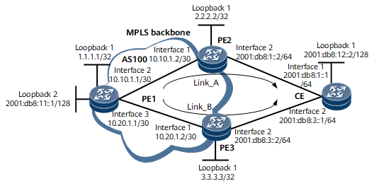
On the network shown in Figure 1, PE1 sets up a VPNv6 peer relationship with PE2 and PE3 and learns two routes to the CE from PE2 and PE3. It is required that load balancing among IPv6 VPN routes be configured on PE1 to load balance the IPv6 VPN traffic destined for CE1 between PE2 and PE3. It is required that load balancing among IPv6 VPN routes be configured on PE1 to load balance the IPv6 VPN traffic destined for CE1 between PE2 and PE3.

Configuration Notes
When configuring load balancing between IPv6 routes, ensure that the RDs configured for the IPv6 VPN instance on PE2 and PE3 are different.
Configuration Roadmap
The configuration roadmap is as follows:
Configure a BGP/MPLS IPv6 VPN, and connect the CE to PE2 and PE3.
Configure load balancing among IPv6 VPN routes for the BGP-VPN instance IPv6 address family on PE1.
Procedure
- Configure IPv6 addresses for interfaces on the backbone network of the VPN and IPv6 addresses for interfaces at the VPN site. For configuration details, see Configuration Files in this section.
- Configure OSPF on the MPLS backbone network to ensure IP connectivity on the backbone network. For configuration details, see Configuration Files in this section.
- Configure MPLS and MPLS LDP both globally and per interface on each node of the MPLS backbone network and establish LDP LSPs between PEs.
# Configure PE1.
<PE1> system-view
[~PE1] mpls lsr-id 1.1.1.1
[*PE1] mpls
[*PE1-mpls] quit
[*PE1] mpls ldp
[*PE1-mpls-ldp] quit
[*PE1] interface gigabitEthernet0/1/8
[*PE1-GigabitEthernet0/1/8] mpls
[*PE1-GigabitEthernet0/1/8] mpls ldp
[*PE1-GigabitEthernet0/1/8] quit
[*PE1] interface gigabitEthernet0/1/16
[*PE1-GigabitEthernet0/1/16] mpls
[*PE1-GigabitEthernet0/1/16] mpls ldp
[*PE1-GigabitEthernet0/1/16] quit
[*PE1] commit
# Configure PE2.
<PE2> system-view
[~PE2] mpls lsr-id 2.2.2.2
[*PE2] mpls
[*PE2-mpls] quit
[*PE2] mpls ldp
[*PE2-mpls-ldp] quit
[*PE2] interface gigabitEthernet0/1/0
[*PE2-GigabitEthernet0/1/0] mpls
[*PE2-GigabitEthernet0/1/0] mpls ldp
[*PE2-GigabitEthernet0/1/0] quit
[*PE2] commit
# Configure PE3.
<PE3> system-view
[~PE3] mpls lsr-id 3.3.3.3
[*PE3] mpls
[*PE3-mpls] quit
[*PE3] mpls ldp
[*PE3-mpls-ldp] quit
[*PE3] interface gigabitEthernet0/1/0
[*PE3-GigabitEthernet0/1/0] mpls
[*PE3-GigabitEthernet0/1/0] mpls ldp
[*PE3-GigabitEthernet0/1/0] quit
[*PE3] commit
Run the display mpls lsp command on PEs. The command output shows that LSPs are set up between PE1 and PE2, and between PE1 and PE3. The following example uses the command output on PE1.
[~PE1] display mpls lsp
2021-04-09 01:14:17.813
Flag after Out IF: (I) - RLFA Iterated LSP, (I*) - Normal and RLFA Iterated LSP
Flag after LDP FRR: (L) - Logic FRR LSP
-------------------------------------------------------------------------------
                 LSP Information: LDP LSP
-------------------------------------------------------------------------------
FEC                In/Out Label  In/Out IF                      Vrf Name
1.1.1.1/32         3/NULL        -/-
2.2.2.2/32         NULL/3        -/GE0/2/0
2.2.2.2/32         1025/3        -/GE0/2/0
3.3.3.3/32         NULL/3        -/GE0/3/0
3.3.3.3/32         1024/3        -/GE0/3/0
- Configure an IPv6-address-family-supporting VPN instance on each PE and bind the interface that connects a PE to a CE to the VPN instance on that PE.
# Configure PE1.
[~PE1] ip vpn-instance vpn1
[*PE1-vpn-instance-vpn1] ipv6-family
[*PE1-vpn-instance-vpn1-af-ipv6] route-distinguisher 100:1
[*PE1-vpn-instance-vpn1-af-ipv6] vpn-target 111:1
[*PE1-vpn-instance-vpn1-af-ipv6] quit
[*PE1-vpn-instance-vpn1] quit
[*PE1] interface loopback2
[*PE1-Loopback2] ip binding vpn-instance vpn1
[*PE1-Loopback2] ipv6 enable
[*PE1-Loopback2] ipv6 address 2001:db8:11::1/128
[*PE1-Loobpack2] quit
[*PE1] commit
# Configure PE2.
[~PE2] ip vpn-instance vpn1
[*PE2-vpn-instance-vpn1] ipv6-family
[*PE2-vpn-instance-vpn1-af-ipv6] route-distinguisher 100:2
[*PE2-vpn-instance-vpn1-af-ipv6] vpn-target 111:1
[*PE2-vpn-instance-vpn1-af-ipv6] quit
[*PE2-vpn-instance-vpn1] quit
[*PE2] interface gigabitethernet0/1/8
[*PE2-GigabitEthernet0/1/8] ip binding vpn-instance vpn1
[*PE2-GigabitEthernet0/1/8] ipv6 enable
[*PE2-GigabitEthernet0/1/8] ipv6 address 2001:db8:1::2 64
[*PE2-GigabitEthernet0/1/8] quit
[*PE2] commit
# Configure PE3.
[~PE3] ip vpn-instance vpn1
[*PE3-vpn-instance-vpn1] ipv6-family
[*PE3-vpn-instance-vpn1-af-ipv6] route-distinguisher 100:3
[*PE3-vpn-instance-vpn1-af-ipv6] vpn-target 111:1
[*PE3-vpn-instance-vpn1-af-ipv6] quit
[*PE3-vpn-instance-vpn1] quit
[*PE3] interface gigabitethernet0/1/8
[*PE3-GigabitEthernet0/1/8] ip binding vpn-instance vpn1
[*PE3-GigabitEthernet0/1/8] ipv6 enable
[*PE3-GigabitEthernet0/1/8] ipv6 address 2001:db8:3::2 64
[*PE3-GigabitEthernet0/1/8] quit
[*PE3] commit
- Establish an EBGP peer relationship between PE2 and the CE, and between PE3 and the CE.
# Configure PE2.
[~PE2] bgp 100
[*PE2-bgp] ipv6-family vpn-instance vpn1
[*PE2-bgp6-vpn1] peer 2001:db8:1::1 as-number 65410
[*PE2-bgp6-vpn1] quit
[*PE2-bgp] quit
[*PE2] commit
# Configure PE3.
[~PE3] bgp 100
[*PE3-bgp] ipv6-family vpn-instance vpn1
[*PE3-bgp6-vpn1] peer 2001:db8:3::1 as-number 65410
[*PE3-bgp6-vpn1] quit
[*PE3-bgp] quit
[*PE3] commit
# Configure the CE to import the routes of Loopback 1 into BGP.
<CE> system-view
[~CE] bgp 65410
[*CE-bgp] router-id 10.10.10.10
[*CE-bgp] peer 2001:db8:1::2 as-number 100
[*CE-bgp] peer 2001:db8:3::2 as-number 100
[*CE-bgp] ipv6-family unicast
[*CE-bgp-af-ipv6] peer 2001:db8:1::2 enable
[*CE-bgp-af-ipv6] peer 2001:db8:3::2 enable
[*CE-bgp-af-ipv6] network 2001:db8:0:1:2::1 128
[*CE-bgp-af-ipv6] quit
[*CE-bgp] quit
[*CE] commit
After completing the configurations, run the display bgp vpnv6 all peer command on PE2 and PE3. The command output shows that the status of the EBGP peer relationships between the PEs and CE is Established.
The following example uses the command output on PE2.
[~PE2] display bgp vpnv6 all peer BGP local router ID : 2.2.2.2 Local AS number : 100 Total number of peers : 2 Peers in established state : 2 Peer V AS MsgRcvd MsgSent OutQ Up/Down State PrefRcv 1.1.1.1 4 100 27 24 0 00:19:33 Established 0 Peer of vpn instance : VPN-Instance vpn1, Router ID 2.2.2.2: Peer V AS MsgRcvd MsgSent OutQ Up/Down State PrefRcv 2001:DB8:1::1 4 65410 0 0 0 01:10:03 Established 0 - Establish MP-IBGP peer relationships between PEs.
# Configure PE1.
[~PE1] bgp 100
[*PE1-bgp] peer 2.2.2.2 as-number 100
[*PE1-bgp] peer 2.2.2.2 connect-interface loopback 1
[*PE1-bgp] peer 3.3.3.3 as-number 100
[*PE1-bgp] peer 3.3.3.3 connect-interface loopback 1
[*PE1-bgp] ipv6-family vpnv6
[*PE1-bgp-af-vpnv6] peer 2.2.2.2 enable
[*PE1-bgp-af-vpnv6] peer 3.3.3.3 enable
[*PE1-bgp-af-vpnv6] quit
[*PE1-bgp] quit
[*PE1] commit
# Configure PE2.
[~PE2] bgp 100
[*PE2-bgp] peer 1.1.1.1 as-number 100
[*PE2-bgp] peer 1.1.1.1 connect-interface loopback 1
[*PE2-bgp] ipv6-family vpnv6
[*PE2-bgp-af-vpnv6] peer 1.1.1.1 enable
[*PE2-bgp-af-vpnv6] quit
[*PE2-bgp] quit
[*PE2-bgp] commit
# Configure PE3.
[~PE3] bgp 100
[*PE3-bgp] peer 1.1.1.1 as-number 100
[*PE3-bgp] peer 1.1.1.1 connect-interface loopback 1
[*PE3-bgp] ipv6-family vpnv6
[*PE3-bgp-af-vpnv6] peer 1.1.1.1 enable
[*PE3-bgp-af-vpnv6] quit
[*PE3-bgp] quit
[*PE3] commit
After completing the configurations, run the display bgp vpnv6 all peer command on PEs. The command output shows that the status of the MP-IBGP peer relationships between PEs is Established.
The following example uses the command output on PE1.
<PE1> display bgp vpnv6 all peer
 BGP local router ID : 1.1.1.1
 Local AS number : 100
 Total number of peers : 2                 Peers in established state : 2
Peer            V    AS  MsgRcvd  MsgSent    OutQ  Up/Down       State PrefRcv
2.2.2.2         4   100       20       17       0 00:13:26 Established       5
3.3.3.3         4   100       24       19       0 00:17:18 Established       5
- Configure load balancing among IPv6 VPN routes.
# Configure PE1.
[~PE1] bgp 100
[~PE1-bgp] ipv6-family vpn-instance vpn1
[*PE1-bgp6-vpn1] maximum load-balancing 2
[*PE1-bgp6-vpn1] quit
[*PE1-bgp] quit
[*PE1] commit
- Verify the configuration.
After completing the configurations, run the display ipv6 routing-table vpn-instance verbose command on PE1. The command output shows that PE2 and PE3 serve as the next hops on the IPv6 VPN routes to the loopback interface on the CE.
<PE1> display ipv6 routing-table vpn-instance vpn1 2001:db8:0:1:2::1
Routing Table : vpn1
Summary Count : 2

 Destination  : 2001:db8:0:1:2::1               PrefixLength : 128
 NextHop      : ::FFFF:2.2.2.2                  Preference   : 255
 Cost         : 0                               Protocol     : BGP
 RelayNextHop : ::FFFF:10.10.1.2                TunnelID     : 0x800003
 Interface    : GigabitEthernet0/1/8            Flags        : RD

 Destination  : 2001:db8:0:1:2::1               PrefixLength : 128
 NextHop      : ::FFFF:3.3.3.3                  Preference   : 255
 Cost         : 0                               Protocol     : BGP
 RelayNextHop : ::FFFF:10.20.1.2                TunnelID     : 0x800001
 Interface    : GigabitEthernet0/1/16            Flags        : RD
Configuration Files
PE1 configuration file
#
 sysname PE1
#
ip vpn-instance vpn1
 ipv6-family
  route-distinguisher 100:1
  apply-label per-instance
  vpn-target 111:1 export-extcommunity
  vpn-target 111:1 import-extcommunity
#
mpls lsr-id 1.1.1.1
#
mpls
#
mpls ldp
#
interface GigabitEthernet0/1/8
 undo shutdown
 ip address 10.10.1.1 255.255.255.252
 mpls
 mpls ldp
#
interface GigabitEthernet0/1/16
 undo shutdown
 ip address 10.20.1.1 255.255.255.252
 mpls
 mpls ldp
#
interface LoopBack1
 ip address 1.1.1.1 255.255.255.255
#
interface LoopBack2
 ip binding vpn-instance vpn1
ipv6 enable
ipv6 address 2001:db8:11::1/128
#
bgp 100
 peer 2.2.2.2 as-number 100
 peer 2.2.2.2 connect-interface LoopBack1
 peer 3.3.3.3 as-number 100
 peer 3.3.3.3 connect-interface LoopBack1
 #
 ipv4-family unicast
  undo synchronization
  peer 2.2.2.2 enable
  peer 3.3.3.3 enable
#
 ipv6-family vpnv6
  policy vpn-target
  peer 2.2.2.2 enable
  peer 3.3.3.3 enable
#
 ipv6-family vpn-instance vpn1
 maximum load-balancing 2
#
ospf 1
 area 0.0.0.0
  network 10.10.1.0 0.0.0.3
  network 10.20.1.0 0.0.0.3
  network 1.1.1.1 0.0.0.0
#
return
PE2 configuration file
#
 sysname PE2
#
ip vpn-instance vpn1
 ipv6-family
  route-distinguisher 100:2
  apply-label per-instance
  vpn-target 111:1 export-extcommunity
  vpn-target 111:1 import-extcommunity
#
mpls lsr-id 2.2.2.2
#
mpls
#
mpls ldp
#
interface GigabitEthernet0/1/0
 undo shutdown
 ip address 10.10.1.2 255.255.255.252
 mpls
 mpls ldp
#
interface GigabitEthernet0/1/8
 undo shutdown
 ipv6 enable
 ip binding vpn-instance vpn1
 ipv6 address 2001:db8:1::2/64
#
interface LoopBack1
 ip address 2.2.2.2 255.255.255.255
#
bgp 100
 peer 1.1.1.1 as-number 100
 peer 1.1.1.1 connect-interface LoopBack1
 #
 ipv4-family unicast
  undo synchronization
  peer 1.1.1.1 enable
#
 ipv6-family vpnv6
  policy vpn-target
  peer 1.1.1.1 enable
#
 ipv6-family vpn-instance vpn1
  peer 2001:db8:1::1 as-number 65410
  import-route direct
#
ospf 1
 area 0.0.0.0
  network 10.10.1.0 0.0.0.3
  network 2.2.2.2 0.0.0.0
#
return
PE3 configuration file
#
 sysname PE3
#
ip vpn-instance vpn1
 ipv6-family
  route-distinguisher 100:3
  apply-label per-instance
  vpn-target 111:1 export-extcommunity
  vpn-target 111:1 import-extcommunity
#
mpls lsr-id 3.3.3.3
#
mpls
#
mpls ldp
#
interface GigabitEthernet0/1/0
 undo shutdown
 ip address 10.20.1.2 255.255.255.252
 mpls
 mpls ldp
#
interface GigabitEthernet0/1/8
 undo shutdown
 ipv6 enable
 ip binding vpn-instance vpn1
 ip address 2001:db8:3::2/64
#
interface LoopBack1
 ip address 3.3.3.3 255.255.255.255
#
bgp 100
 peer 1.1.1.1 as-number 100
 peer 1.1.1.1 connect-interface LoopBack1
 #
 ipv4-family unicast
  undo synchronization
  peer 1.1.1.1 enable
#
 ipv6-family vpnv6
  policy vpn-target
  peer 1.1.1.1 enable
#
 ipv6-family vpn-instance vpn1
  peer 2001:db8:3::1 as-number 65410
#
ospf 1
 area 0.0.0.0
  network 10.20.1.0 0.0.0.3
  network 3.3.3.3 0.0.0.0
#
return
CE configuration file
#
 sysname CE
#
interface GigabitEthernet0/1/0
 undo shutdown
 ipv6 enable
 ipv6 address 2001:db8:1::1/64
#
interface GigabitEthernet0/1/8
 undo shutdown
 ipv6 enable
 ipv6 address 2001:db8:3::1/64
#
interface LoopBack1
 ipv6 enable
 ipv6 address 2001:db8:0:1:2::1/128
#
bgp 65410
 router-id 10.10.10.10
 peer 2001:db8:1::2 as-number 100
 peer 2001:db8:3::2 as-number 100
 #
 ipv4-family unicast
  undo synchronization
 #
  ipv6-family unicast
  undo synchronization
  network 2001:db8:0:1:2::1 128
  peer 2001:db8:1::2 enable
  peer 2001:db8:3::2 enable
#
return