Example for Configuring Inter-AS IPv6 VPN Option A
This section provides an example for deploying an IPv6 VPN instance on ASBRs to implement inter-AS IPv6 VPN Option A, also called VRF-to-VRF.
Networking Requirements
Inter-AS IPv6 VPN Option A can be deployed if IPv6 VPN services need to be provided to customers across ASs on a carrier's backbone network.
It is easy to configure inter-AS IPv6 VPN Option A. You only need to configure an IPv6-address-family-supporting VPN instance on each ASBR and configure the ASBRs to view each other as a CE. If the services of many VPNs need to be transmitted across ASs, the requirements for ASBR performance will be high.
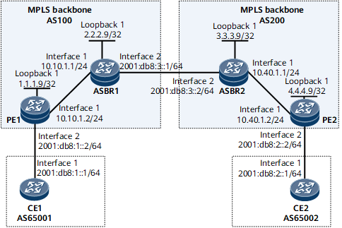
As shown in Figure 1, CE1 and CE2 belong to the same VPN. CE1 accesses PE1 in AS100; CE2 accesses PE2 in AS200.
It is required that Option A be configured to implement inter-AS IPv6 VPN so that CE1 and CE2 can access each other.
Configuration Roadmap
The configuration roadmap is as follows:
Establish EBGP peer relationships between PEs and CEs and establish MP-IBGP peer relationships between the PEs and ASBRs.
Configure an IPv6-address-family-supporting VPN instance and bind the VPN instance to the interface connecting to the peer ASBR on each ASBR.
Data Preparation
To complete the configuration, you need the following data:
MPLS LSR IDs of the PEs and ASBRs
Name of the IPv6-address-family-supporting VPN instance configured on each PE and ASBR, and the RD and VPN targets of the VPN instance
Procedure
- Configure an IGP on the MPLS backbone networks in AS100 and AS200 for IP connectivity between the ASBR and the PE within each MPLS backbone network.
This example uses OSPF as the IGP. For configuration details, see Configuration Files in this section.

The 32-bit IP address of the loopback interface that functions as the LSR ID needs to be advertised by using OSPF.
After the configurations are complete, the OSPF neighbor relationship can be established between the ASBR and the PE in the same AS. Run the display ospf peer command. The command output shows that the neighbor relationship is in the Full state.
The ASBR and PE in the same AS can learn the LSR ID (IP address of Loopback1) of each other and ping each other successfully.
- Configure MPLS and MPLS LDP both globally and per interface on each node of the MPLS backbone networks in AS100 and AS200 and set up LDP LSPs.
# Configure PE1.
<PE1> system-view
[~PE1] mpls lsr-id 1.1.1.9
[*PE1] mpls
[*PE1-mpls] quit
[*PE1] mpls ldp
[*PE1-mpls-ldp] quit
[*PE1] interface gigabitEthernet0/1/0
[*PE1-GigabitEthernet0/1/0] mpls
[*PE1-GigabitEthernet0/1/0] mpls ldp
[*PE1-GigabitEthernet0/1/0] quit
[*PE1] commit
# Configure ASBR1.
<ASBR1> system-view
[~ASBR1] mpls lsr-id 2.2.2.9
[*ASBR1] mpls
[*ASBR1-mpls] quit
[*ASBR1] mpls ldp
[*ASBR1-mpls-ldp] quit
[*ASBR1] interface gigabitEthernet0/1/0
[*ASBR1-GigabitEthernet0/1/0] mpls
[*ASBR1-GigabitEthernet0/1/0] mpls ldp
[*ASBR1-GigabitEthernet0/1/0] quit
[*ASBR1] commit
# Configure ASBR2.
<ASBR2> system-view
[~ASBR2] mpls lsr-id 3.3.3.9
[*ASBR2] mpls
[*ASBR2-mpls] quit
[*ASBR2] mpls ldp
[*ASBR2-mpls-ldp] quit
[*ASBR2] interface gigabitEthernet0/1/0
[*ASBR2-GigabitEthernet0/1/0] mpls
[*ASBR2-GigabitEthernet0/1/0] mpls ldp
[*ASBR2-GigabitEthernet0/1/0] quit
[*ASBR2] commit
# Configure PE2.
<PE2> system-view
[~PE2] mpls lsr-id 4.4.4.9
[*PE2] mpls
[*PE2-mpls] quit
[*PE2] mpls ldp
[*PE2-mpls-ldp] quit
[*PE2] interface gigabitEthernet0/1/0
[*PE2-GigabitEthernet0/1/0] mpls
[*PE2-GigabitEthernet0/1/0] mpls ldp
[*PE2-GigabitEthernet0/1/0] quit
[*PE20] commit
After the configurations are complete, an LDP peer relationship can be set up between the PE and the ASBR in the same AS. Run the display mpls ldp session command on each device. The command output shows that the session state is Operational.
The following example uses the command output on PE1.
[~PE1] display mpls ldp session
 LDP Session(s) in Public Network
 Codes: LAM(Label Advertisement Mode), SsnAge Unit(DDDD:HH:MM)
 An asterisk (*) before a session means the session is being deleted.
--------------------------------------------------------------------------
 PeerID             Status      LAM  SsnRole  SsnAge      KASent/Rcv
--------------------------------------------------------------------------
2.2.2.9:0          Operational DU   Passive  0000:00:02  9/9
--------------------------------------------------------------------------
 TOTAL: 1 session(s) Found.
- Configure a basic BGP/MPLS IPv6 VPN in AS100 and AS200.
The VPN targets of the IPv6-address-family-supporting VPN instance configured on the ASBR and the PE in the same AS must match. This is not required for the PEs in different ASs.
# Configure CE1.
<CE1> system-view
[~CE1] interface gigabitethernet 0/1/0
[~CE1-GigabitEthernet0/1/0] ipv6 enable
[*CE1-GigabitEthernet0/1/0] ipv6 address 2001:db8:1::1 64
[*CE1-GigabitEthernet0/1/0] quit
[*CE1] bgp 65001
[*CE1-bgp] router-id 10.10.10.10
[*CE1-bgp] peer 2001:db8:1::2 as-number 100
[*CE1-bgp] ipv6-family unicast
[*CE1-bgp-af-ipv6] peer 2001:db8:1::2 enable
[*CE1-bgp-af-ipv6] import-route direct
[*CE1-bgp-af-ipv6] quit
[*CE1-bgp] quit
[*CE1] commit
# Configure PE1 to set up an EBGP peer relationship with CE1.
[~PE1] ip vpn-instance vpn1
[*PE1-vpn-instance-vpn1] ipv6-family
[*PE1-vpn-instance-vpn1-af-ipv6] route-distinguisher 100:1
[*PE1-vpn-instance-vpn1-af-ipv6] vpn-target 1:1 both
[*PE1-vpn-instance-vpn1-af-ipv6] quit
[*PE1-vpn-instance-vpn1] quit
[*PE1] interface gigabitethernet 0/1/8
[*PE1-GigabitEthernet0/1/8] ip binding vpn-instance vpn1
[*PE1-GigabitEthernet0/1/8] ipv6 enable
[*PE1-GigabitEthernet0/1/8] ipv6 address 2001:db8:1::2 64
[*PE1-GigabitEthernet0/1/8] quit
[*PE1] bgp 100
[*PE1-bgp] ipv6-family vpn-instance vpn1
[*PE1-bgp6-vpn1] peer 2001:db8:1::1 as-number 65001
[*PE1-bgp6-vpn1] import-route direct
[*PE1-bgp6-vpn1] quit
[*PE1-bgp] quit
[*PE1] commit
# Configure PE1 to set up an MP-IBGP peer relationship with ASBR1.
[~PE1] bgp 100
[*PE1-bgp] peer 2.2.2.9 as-number 100
[*PE1-bgp] peer 2.2.2.9 connect-interface loopback 1
[*PE1-bgp] ipv6-family vpnv6
[*PE1-bgp-af-vpnv6] peer 2.2.2.9 enable
[*PE1-bgp-af-vpnv6] quit
[*PE1-bgp] quit
[*PE1] commit
# Configure ASBR1 to set up an MP-IBGP peer relationship with PE1.
[~ASBR1] bgp 100
[*ASBR1-bgp] peer 1.1.1.9 as-number 100
[*ASBR1-bgp] peer 1.1.1.9 connect-interface loopback 1
[*ASBR1-bgp] ipv6-family vpnv6
[*ASBR1-bgp-af-vpnv6] peer 1.1.1.9 enable
[*ASBR1-bgp-af-vpnv6] quit
[*ASBR1-bgp] quit
[*ASBR1] commit
The configurations of CE2, PE2, and ASBR2 are similar to the configurations of CE1, PE1, and ASBR1 respectively. For configuration details, see Configuration Files in this section.
After completing the configurations, run the display bgp vpnv6 vpn-instance peer command on PEs. The command output shows that the BGP peer relationships between the PEs and the CEs are in the Established state. Run the display bgp vpnv6 all peer command on the PE or ASBR. The command output shows that the BGP peer relationship is established between the PEs and the CEs, and between the PEs and ASBRs.
The following example uses the command output on PE1.
[~PE1] display bgp vpnv6 vpn-instance vpn1 peer
 BGP local router ID : 1.1.1.9
 Local AS number : 100
 Total number of peers : 1                 Peers in established state : 1
  Peer            V    AS  MsgRcvd  MsgSent  OutQ  Up/Down       State PrefRcv
  2001:db8:1::1  4 65001       14       12     0 00:08:36 Established       1
[~PE1] display bgp vpnv6 all peer
 BGP local router ID : 1.1.1.9
 Local AS number : 100
 Total number of peers : 2                 Peers in established state : 2
  Peer            V    AS  MsgRcvd  MsgSent  OutQ  Up/Down       State PrefRcv
  2.2.2.9         4   100       13       12     0 00:09:10 Established       0
    Peer of vpn instance :

  VPN-Instance vpn1, router ID 1.1.1.9:
  2001:db8:1::1   4 65001       17       14     0 00:11:09 Established       1
- Configure inter-AS VPN in VRF-to-VRF mode.
# Create an IPv6-address-family-supporting VPN instance on ASBR1 and bind the interface that connects ASBR1 to ASBR2 (viewed as a CE by ASBR1) to the VPN instance.
[~ASBR1] ip vpn-instance vpn1
[*ASBR1-vpn-instance-vpn1] ipv6-family
[*ASBR1-vpn-instance-vpn1-af-ipv6] route-distinguisher 100:2
[*ASBR1-vpn-instance-vpn1-af-ipv6] vpn-target 1:1 both
[*ASBR1-vpn-instance-vpn1-af-ipv6] quit
[*ASBR1-vpn-instance-vpn1] quit
[*ASBR1] interface gigabitEthernet 0/1/8
[*ASBR1-GigabitEthernet0/1/8] ip binding vpn-instance vpn1
[*ASBR1-GigabitEthernet0/1/8] ipv6 enable
[*ASBR1-GigabitEthernet0/1/8] ipv6 address 2001:db8:3::1 64
[*ASBR1-GigabitEthernet0/1/8] quit
[*ASBR1] commit
# Create an IPv6-address-family-supporting VPN instance on ASBR2 and bind the interface that connects ASBR2 to ASBR1 (viewed as a CE by ASBR2) to the VPN instance.
[~ASBR2] ip vpn-instance vpn1
[*ASBR2-vpn-instance-vpn1] ipv6-family
[*ASBR2-vpn-instance-vpn1-af-ipv6] route-distinguisher 200:2
[*ASBR2-vpn-instance-vpn1-af-ipv6] vpn-target 2:2 both
[*ASBR2-vpn-instance-vpn1-af-ipv6] quit
[*ASBR2-vpn-instance-vpn1] quit
[*ASBR2] interface gigabitEthernet 0/1/8
[*ASBR2-GigabitEthernet0/1/8] ip binding vpn-instance vpn1
[*ASBR2-GigabitEthernet0/1/8] ipv6 enable
[*ASBR2-GigabitEthernet0/1/8] ipv6 address 2001:db8:3::2 64
[*ASBR2-GigabitEthernet0/1/8] quit
[*ASBR2] commit
# Configure ASBR1 to set up an EBGP peer relationship with ASBR2.
[~ASBR1] bgp 100
[*ASBR1-bgp] ipv6-family vpn-instance vpn1
[*ASBR1-bgp6-vpn1] peer 2001:db8:3::2 as-number 200
[*ASBR1-bgp6-vpn1] import-route direct
[*ASBR1-bgp6-vpn1] quit
[*ASBR1-bgp] quit
[*ASBR1] commit
# Configure ASBR2 to set up an EBGP peer relationship with ASBR1.
[~ASBR2] bgp 200
[*ASBR2-bgp] ipv6-family vpn-instance vpn1
[*ASBR2-bgp6-vpn1] peer 2001:db8:3::1 as-number 100
[*ASBR2-bgp6-vpn1] import-route direct
[*ASBR2-bgp6-vpn1] quit
[*ASBR2-bgp] quit
[*ASBR2] commit
After completing the configurations, run the display bgp vpnv6 vpn-instance peer command. The command output shows that the BGP peer relationship between the ASBRs is in the Established state.
- Verify the configuration.
After the configurations are complete, the CEs can learn the routes to each other's interfaces and ping each other. The following example uses the command output on CE1.
[~CE1] display ipv6 routing-table
Routing Table : _public_
         Destinations : 8        Routes : 8

 Destination  : ::1                             PrefixLength : 128
 NextHop      : ::1                             Preference   : 0
 Cost         : 0                               Protocol     : Direct
 RelayNextHop : ::                              TunnelID     : 0x0
 Interface    : InLoopBack0                     Flags        : D

 Destination  : ::FFFF:127.0.0.0                PrefixLength : 104
 NextHop      : ::FFFF:127.0.0.1                Preference   : 0
 Cost         : 0                               Protocol     : Direct
 RelayNextHop : ::                              TunnelID     : 0x0
 Interface    : InLoopBack0                     Flags        : D

 Destination  : ::FFFF:127.0.0.1                PrefixLength : 128
 NextHop      : ::1                             Preference   : 0
 Cost         : 0                               Protocol     : Direct
 RelayNextHop : ::                              TunnelID     : 0x0
 Interface    : InLoopBack0                     Flags        : D

 Destination  : 2001:db8:1::                    PrefixLength : 64
 NextHop      : 2001:db8:1::1                   Preference   : 0
 Cost         : 0                               Protocol     : Direct
 RelayNextHop : ::                              TunnelID     : 0x0
 Interface    : GigabitEthernet0/1/0            Flags        : D

 Destination  : 2001:db8:1::1                   PrefixLength : 128
 NextHop      : ::1                             Preference   : 0
 Cost         : 0                               Protocol     : Direct
 RelayNextHop : ::                              TunnelID     : 0x0
 Interface    : GigabitEthernet0/1/0            Flags        : D

 Destination  : 2001:db8:2::                    PrefixLength : 64
 NextHop      : 2001:db8:1::2                   Preference   : 255
 Cost         : 0                               Protocol     : BGP
 RelayNextHop : ::                              TunnelID     : 0x0
 Interface    : GigabitEthernet0/1/0            Flags        : D

 Destination  : 2001:db8:3::                    PrefixLength : 64
 NextHop      : 2001:db8:1::2                   Preference   : 255
 Cost         : 0                               Protocol     : BGP
 RelayNextHop : ::                              TunnelID     : 0x0
 Interface    : GigabitEthernet0/1/0            Flags        : D

 Destination  : FE80::                          PrefixLength : 10
 NextHop      : ::                              Preference   : 0
 Cost         : 0                               Protocol     : Direct
 RelayNextHop : ::                              TunnelID     : 0x0
 Interface    : NULL0                           Flags        : D
[~CE1] ping ipv6 2001:db8:2::1
  PING 2001:db8:2::1 : 56  data bytes, press CTRL_C to break
    Reply from 2001:db8:2::1
    bytes=56 Sequence=1 hop limit=60  time = 94 ms
    Reply from 2001:db8:2::1
    bytes=56 Sequence=2 hop limit=60  time = 109 ms
    Reply from 2001:db8:2::1
    bytes=56 Sequence=3 hop limit=60  time = 110 ms
    Reply from 2001:db8:2::1
    bytes=56 Sequence=4 hop limit=60  time = 94 ms
    Reply from 2001:db8:2::1
    bytes=56 Sequence=5 hop limit=60  time = 110 ms
  --- 2001:db8:2::1 ping statistics ---
    5 packet(s) transmitted
    5 packet(s) received
    0.00% packet loss
    round-trip min/avg/max = 94/103/110 ms
Run the display ipv6 routing-table vpn-instance command on either of ASBRs. The command output shows the routing table of the VPN instance IPv6 address maintained on the ASBR. The following example uses the command output on ASBR1.
<ASBR1> display ipv6 routing-table vpn-instance vpn1
Routing Table : vpn1
         Destinations : 5        Routes : 5

 Destination  : 2001:db8:1::                    PrefixLength : 64
 NextHop      : ::FFFF:1.1.1.9                  Preference   : 255
 Cost         : 0                               Protocol     : BGP
 RelayNextHop : ::                              TunnelID     : 0xa0010082
 Interface    : NULL0                           Flags        : RD

 Destination  : 2001:db8:2::                    PrefixLength : 64
 NextHop      : 2001:db8:3::2                   Preference   : 255
 Cost         : 0                               Protocol     : BGP
 RelayNextHop : ::                              TunnelID     : 0x0
 Interface    : GigabitEthernet0/1/8            Flags        : D

 Destination  : 2001:db8:3::                    PrefixLength : 64
 NextHop      : 2001:db8:3::1                   Preference   : 0
 Cost         : 0                               Protocol     : Direct
 RelayNextHop : ::                              TunnelID     : 0x0
 Interface    : GigabitEthernet0/1/8            Flags        : D

 Destination  : 2001:db8:3::1                   PrefixLength : 128
 NextHop      : ::1                             Preference   : 0
 Cost         : 0                               Protocol     : Direct
 RelayNextHop : ::                              TunnelID     : 0x0
 Interface    : GigabitEthernet0/1/8            Flags        : D

 Destination  : FE80::                          PrefixLength : 10
 NextHop      : ::                              Preference   : 0
 Cost         : 0                               Protocol     : Direct
 RelayNextHop : ::                              TunnelID     : 0x0
 Interface    : NULL0                           Flags        : D
Run the display bgp vpnv6 all routing-table command on either ASBR. The command output shows the VPNv6 routes on the ASBR. The following example uses the command output on ASBR1.
<ASBR1> display bgp vpnv6 all routing-table
BGP Local router ID is 2.2.2.9
 Status codes: * - valid, > - best, d - damped, x - best external, a - add path,
               h - history,  i - internal, s - suppressed, S - Stale
               Origin : i - IGP, e - EGP, ? - incomplete


 Total number of routes from all PE: 4
 Route Distinguisher: 100:1


 *>i Network  : 2001:db8:1::                             PrefixLen : 64
     NextHop  : ::FFFF:1.1.1.9                           LocPrf    : 100
     MED      : 0                                        PrefVal   : 0
     Label    : 105472
     Path/Ogn : ?

 Route Distinguisher: 100:2


 *>  Network  : 2001:db8:2::                             PrefixLen : 64
     NextHop  : 2001:db8:3::2                            LocPrf    :
     MED      :                                          PrefVal   : 0
     Label    : NULL
     Path/Ogn : 200 ?
 *>  Network  : 2001:db8:3::                             PrefixLen : 64
     NextHop  : ::                                       LocPrf    :
     MED      : 0                                        PrefVal   : 0
     Label    : NULL
     Path/Ogn : ?
 *
     NextHop  : 2001:db8:3::2                            LocPrf    :
     MED      : 0                                        PrefVal   : 0
     Label    : NULL
     Path/Ogn : 200 ?

 VPN-Instance vpn1 :

 Total Number of Routes: 4
 *>i Network  : 2001:db8:1::                             PrefixLen : 64
     NextHop  : ::FFFF:1.1.1.9                           LocPrf    : 100
     MED      : 0                                        PrefVal   : 0
     Label    : 105472
     Path/Ogn : ?
 *>  Network  : 2001:db8:2::                             PrefixLen : 64
     NextHop  : 2001:db8:3::2                            LocPrf    :
     MED      :                                          PrefVal   : 0
     Label    : NULL
     Path/Ogn : 200 ?
 *>  Network  : 2001:db8:3::                             PrefixLen : 64
     NextHop  : ::                                       LocPrf    :
     MED      : 0                                        PrefVal   : 0
     Label    : NULL
     Path/Ogn : ?
 *
     NextHop  : 2001:db8:3::2                            LocPrf    :
     MED      : 0                                        PrefVal   : 0
     Label    : NULL
     Path/Ogn : 200 ?
Configuration Files
CE1 configuration file
#
 sysname CE1
#
interface GigabitEthernet0/1/0
 undo shutdown
 ipv6 enable
 ipv6 address 2001:db8:1::1/64
#
bgp 65001
 router-id 10.10.10.10
 peer 2001:db8:1::2 as-number 100
 #
 ipv4-family unicast
  undo synchronization
 #
 ipv6-family unicast
  undo synchronization
  import-route direct
  peer 2001:db8:1::2 enable
#
return
PE1 configuration file
#
 sysname PE1
#
ip vpn-instance vpn1
 ipv6-family
  route-distinguisher 100:1
  apply-label per-instance
  vpn-target 1:1 export-extcommunity
  vpn-target 1:1 import-extcommunity
#
mpls lsr-id 1.1.1.9
#
mpls
#
mpls ldp
#
interface GigabitEthernet0/1/0
 undo shutdown
 ip address 10.10.1.2 255.255.255.0
 mpls
 mpls ldp
#
interface GigabitEthernet0/1/8
 undo shutdown
 ip binding vpn-instance vpn1
 ipv6 enable
 ipv6 address 2001:db8:1::2/64
#
interface LoopBack1
 ip address 1.1.1.9 255.255.255.255
#
bgp 100
 peer 2.2.2.9 as-number 100
 peer 2.2.2.9 connect-interface LoopBack1
 #
 ipv4-family unicast
  undo synchronization
  peer 2.2.2.9 enable
 #
 ipv6-family vpnv6
  policy vpn-target
  peer 2.2.2.9 enable
#
 ipv6-family vpn-instance vpn1
  peer 2001:db8:1::1 as-number 65001
  import-route direct
#
ospf 1
 area 0.0.0.0
  network 1.1.1.9 0.0.0.0
  network 10.10.1.0 0.0.0.255
#
return
ASBR1 configuration file
#
 sysname ASBR1
#
ip vpn-instance vpn1
 ipv6-family
  route-distinguisher 100:2
  apply-label per-instance
  vpn-target 1:1 export-extcommunity
  vpn-target 1:1 import-extcommunity
#
mpls lsr-id 2.2.2.9
#
mpls
#
mpls ldp
#
interface GigabitEthernet0/1/0
 undo shutdown
 ip address 10.10.1.1 255.255.255.0
 mpls
 mpls ldp
#
interface GigabitEthernet0/1/8
 undo shutdown
 ip binding vpn-instance vpn1
 ipv6 enable
 ipv6 address 2001:db8:3::1/64
#
interface LoopBack1
 ip address 2.2.2.9 255.255.255.255
#
bgp 100
 peer 1.1.1.9 as-number 100
 peer 1.1.1.9 connect-interface LoopBack1
 #
 ipv4-family unicast
  undo synchronization
  import-route direct
  peer 1.1.1.9 enable
 #
 ipv6-family vpnv6
  policy vpn-target
  peer 1.1.1.9 enable
#
 ipv6-family vpn-instance vpn1
  peer 2001:db8:3::2 as-number 200
  import-route direct
#
ospf 1
 area 0.0.0.0
  network 2.2.2.9 0.0.0.0
  network 10.10.1.0 0.0.0.255
#
return
ASBR2 configuration file
#
 sysname ASBR2
#
ip vpn-instance vpn1
 ipv6-family
  route-distinguisher 200:2
  apply-label per-instance
  vpn-target 2:2 export-extcommunity
  vpn-target 2:2 import-extcommunity
#
mpls lsr-id 3.3.3.9
#
mpls
#
mpls ldp
#
interface GigabitEthernet0/1/0
 undo shutdown
 ip address 10.40.1.1 255.255.255.0
 mpls
 mpls ldp
#
interface GigabitEthernet0/1/8
 undo shutdown
 ip binding vpn-instance vpn1
 ipv6 enable
 ipv6 address 2001:db8:3::2/64
#
interface LoopBack1
 ip address 3.3.3.9 255.255.255.255
#
bgp 200
 peer 4.4.4.9 as-number 200
 peer 4.4.4.9 connect-interface LoopBack1
 #
 ipv4-family unicast
  undo synchronization
  peer 4.4.4.9 enable
 #
 ipv6-family vpnv6
  policy vpn-target
  peer 4.4.4.9 enable
#
 ipv6-family vpn-instance vpn1
  peer 2001:db8:3::1 as-number 100
  import-route direct
#
ospf 1
 area 0.0.0.0
  network 3.3.3.9 0.0.0.0
  network 10.40.1.0 0.0.0.255
#
return
PE2 configuration file
#
 sysname PE2
#
ip vpn-instance vpn1
 ipv6-family
  route-distinguisher 200:1
  apply-label per-instance
  vpn-target 2:2 export-extcommunity
  vpn-target 2:2 import-extcommunity
#
mpls lsr-id 4.4.4.9
#
mpls
#
mpls ldp
#
interface GigabitEthernet0/1/0
 undo shutdown
 ip address 10.40.1.2 255.255.255.0
 mpls
 mpls ldp
#
interface GigabitEthernet0/1/8
 undo shutdown
 ip binding vpn-instance vpn1
 ipv6 enable
 ipv6 address 2001:db8:2::2/64
#
interface LoopBack1
 ip address 4.4.4.9 255.255.255.255
#
bgp 200
 peer 3.3.3.9 as-number 200
 peer 3.3.3.9 connect-interface LoopBack1
 #
 ipv4-family unicast
  undo synchronization
  peer 3.3.3.9 enable
 #
 ipv6-family vpnv6
  policy vpn-target
  peer 3.3.3.9 enable
#
 ipv6-family vpn-instance vpn1
  peer 2001:db8:2::1 as-number 65002
  import-route direct
#
ospf 1
 area 0.0.0.0
  network 4.4.4.9 0.0.0.0
  network 10.40.1.0 0.0.0.255
#
return
CE2 configuration file
#
 sysname CE2
#
interface GigabitEthernet0/1/0
 undo shutdown
 ipv6 enable
 ipv6 address 2001:db8:2::1/64
#
bgp 65002
 router-id 11.11.11.11
 peer 2001:db8:2::2 as-number 200
 #
 ipv4-family unicast
  undo synchronization
 #
 ipv6-family unicast
  undo synchronization
  import-route direct
  peer 2001:db8:2::2 enable
#
return