Example for Configuring an MCE (IPv6)
Open Shortest Path First (OSPF) multi-VPN-instance can be configured on a customer edge (CE) to isolate different types of services on a local area network (LAN).
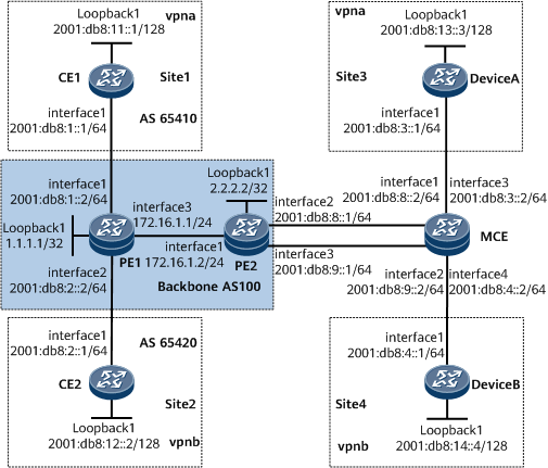
Networking Requirements
CE1 in branch A and CE2 in branch B belong to vpna and vpnb, respectively.
The MCE connects to the sites on vpna and vpnb at the headquarters.
vpna and vpnb use different VPN targets.
The headquarters use Device A and Device B to communicate with branches A and B, respectively.
This configuration ensures that users on the same VPN can communicate with each other and that users on different VPNs cannot communicate with each other.
Configuration Notes
When configuring an MCE, note the following points:
Different VPN instances must be configured on the MCE and bound to different interfaces.
Routing loop detection must be disabled on the MCE so that the MCE exchanges routing information with the PEs using OSPFv3 multi-vpn-instance.
Configuration Roadmap
The configuration roadmap is as follows:
Configure OSPF on PEs and enable MP-IBGP on the PEs to exchange VPN routing information.
Establish BGP4+ peer relationships between the PEs and CEs and import VPN routes into the PEs' VRF tables.
Configure OSPFv3 multi-vpn-instance on the MCE and PE2 to exchange VPN routing information.
Configure RIPng on the MCE, Device A, and Device B to exchange VPN routing information.

Configuring OSPFv3 multi-vpn-instance on the MCE and PE2 includes the following configurations:
Import BGP routes to PE2's OSPFv3 process in which OSPFv3 multi-vpn-instance is configured on the MCE and PE2. Then advertise PE1's VPN routes to the MCE.
Import all routes to PE2's OSPFv3 process in the BGP-VPN instance IPv6 address family, in which OSPFv3 multi-VPN-instance is configured on the MCE and PE2, in PE2's BGP view. Then advertise MCE's VPN routes to PE1.
Data Preparation
To complete the configuration, you need the following data:
VPN instances vpna and vpnb on PE1, PE2, and the MCE for each service; vpna's VPN target 111:1; and vpnb's VPN target 222:1
vpna's OSPFv3 process ID 100 and vpnb's OSPFv3 process ID 200
vpna's RIPng process ID 100 and vpnb's RIPng process ID 200 used for importing VPN routes of sites 3 and 4 on the MCE
Procedure
- Enable OSPF on the PEs on the backbone network to ensure that the PEs interwork with each other.
For configuration details, see Configuration Files in this section.
After this configuration is complete, the PEs can learn the IP address of each other's loopback1 interface.
The following example uses the command output on PE2.
<PE2> display ip routing-table
Route Flags: R - relay, D - download to fib, T - to vpn-instance, B - black hole route
------------------------------------------------------------------------------
Routing Table : _public_
         Destinations : 9        Routes : 9

Destination/Mask    Proto  Pre  Cost        Flags NextHop         Interface

        1.1.1.1/32  OSPF   10   1             D  172.16.1.1      GigabitEthernet0/1/0
        2.2.2.2/32  Direct 0    0             D  127.0.0.1       LoopBack1
      127.0.0.0/8   Direct 0    0             D  127.0.0.1       InLoopBack0
      127.0.0.1/32  Direct 0    0             D  127.0.0.1       InLoopBack0
127.255.255.255/32  Direct 0    0             D  127.0.0.1       InLoopBack0
     172.16.1.0/24  Direct 0    0             D  172.16.1.2      GigabitEthernet0/1/0
     172.16.1.2/32  Direct 0    0             D  127.0.0.1       GigabitEthernet0/1/0
   172.16.1.255/32  Direct 0    0             D  127.0.0.1       GigabitEthernet0/1/0
255.255.255.255/32  Direct 0    0             D  127.0.0.1       InLoopBack0
- Configure basic MPLS functions and enable MPLS LDP on the PEs on the backbone network. Then establish LDP LSPs between the PEs.
For configuration details, see Configuration Files in this section.
After this configuration is complete, run the display mpls ldp session command on the PEs. The command output shows that an MPLS LDP session has been established between the PEs and its status is Operational.
In the following example, the display on PE2 is used.
<PE2> display mpls ldp session LDP Session(s) in Public Network Codes: LAM(Label Advertisement Mode), SsnAge Unit(DDDD:HH:MM) An asterisk (*) before a session means the session is being deleted. -------------------------------------------------------------------------- PeerID Status LAM SsnRole SsnAge KASent/Rcv -------------------------------------------------------------------------- 1.1.1.1:0 Operational DU Active 0000:00:07 32/32 -------------------------------------------------------------------------- TOTAL: 1 Session(s) Found. - Configure VPN instances on PE1 and PE2, and bind the VPN instances on PE1 to PE1's interfaces connected to CE1 and CE2 and bind the VPN instances on PE2 to PE2's interfaces connected to the MCE.
# Configure PE1.
<PE1> system-view
[~PE1] ip vpn-instance vpna
[*PE1-vpn-instance-vpna] ipv6-family
[*PE1-vpn-instance-vpna-af-ipv6] route-distinguisher 100:1
[*PE1-vpn-instance-vpna-af-ipv6] vpn-target 111:1 both
[*PE1-vpn-instance-vpna-af-ipv6] quit
[*PE1-vpn-instance-vpna] quit
[*PE1] ip vpn-instance vpnb
[*PE1-vpn-instance-vpnb] ipv6-family
[*PE1-vpn-instance-vpnb-af-ipv6] route-distinguisher 100:2
[*PE1-vpn-instance-vpnb-af-ipv6] vpn-target 222:2 both
[*PE1-vpn-instance-vpnb-af-ipv6] quit
[*PE1-vpn-instance-vpnb] quit
[*PE1] interface gigabitethernet0/1/0
[*PE1-GigabitEthernet0/1/0] ip binding vpn-instance vpna
[*PE1-GigabitEthernet0/1/0] ipv6 enable
[*PE1-GigabitEthernet0/1/0] ipv6 address 2001:db8:1::2 64
[*PE1-GigabitEthernet0/1/0] quit
[*PE1] interface gigabitethernet0/1/8
[*PE1-GigabitEthernet0/1/8] ip binding vpn-instance vpnb
[*PE1-GigabitEthernet0/1/8] ipv6 enable
[*PE1-GigabitEthernet0/1/8] ipv6 address 2001:db8:2::2 64
[*PE1-GigabitEthernet0/1/8] quit
[*PE1] commit
# Configure PE2.
<PE2> system-view
[~PE2] ip vpn-instance vpna
[*PE2-vpn-instance-vpna] ipv6-family
[*PE2-vpn-instance-vpna-af-ipv6] route-distinguisher 200:1
[*PE2-vpn-instance-vpna-af-ipv6] vpn-target 111:1 both
[*PE2-vpn-instance-vpna-af-ipv6] quit
[*PE2-vpn-instance-vpna] quit
[*PE2] ip vpn-instance vpnb
[*PE2-vpn-instance-vpnb] ipv6-family
[*PE2-vpn-instance-vpnb-af-ipv6] route-distinguisher 200:2
[*PE2-vpn-instance-vpnb-af-ipv6] vpn-target 222:2 both
[*PE2-vpn-instance-vpnb-af-ipv6] quit
[*PE2-vpn-instance-vpnb] quit
[*PE2] interface gigabitethernet0/1/8
[*PE2-GigabitEthernet0/1/8] ip binding vpn-instance vpna
[*PE2-GigabitEthernet0/1/8] ipv6 enable
[*PE2-GigabitEthernet0/1/8] ipv6 address 2001:db8:8::1 64
[*PE2-GigabitEthernet0/1/8] quit
[*PE2]interface gigabitethernet0/1/16
[*PE2-GigabitEthernet0/1/16] ip binding vpn-instance vpnb
[*PE2-GigabitEthernet0/1/16] ipv6 enable
[*PE2-GigabitEthernet0/1/16] ipv6 address 2001:db8:9::1 64
[*PE2-GigabitEthernet0/1/16] quit
[*PE2] commit
- Configure VPN instances on the MCE, and bind the VPN instances to the MCE's interfaces connected to site 3, site 4, and PE2.
<HUAWEI> system-view
[~HUAWEI] sysname MCE
[*HUAWEI] commit
[~MCE] ip vpn-instance vpna
[*MCE-vpn-instance-vpna] ipv6-family
[*MCE-vpn-instance-vpna-af-ipv6] route-distinguisher 100:1
[*MCE-vpn-instance-vpna-af-ipv6] quit
[*MCE-vpn-instance-vpna] quit
[*MCE] ip vpn-instance vpnb
[*MCE-vpn-instance-vpnb] ipv6-family
[*MCE-vpn-instance-vpnb-af-ipv6] route-distinguisher 100:2
[*MCE-vpn-instance-vpnb-af-ipv6] quit
[*MCE-vpn-instance-vpnb] quit
[*MCE] interface gigabitethernet0/1/16
[*MCE-GigabitEthernet0/1/16] ip binding vpn-instance vpna
[*MCE-GigabitEthernet0/1/16] ipv6 enable
[*MCE-GigabitEthernet0/1/16] ipv6 address 2001:db8:3::2 64
[*MCE-GigabitEthernet0/1/16] quit
[*MCE] interface gigabitethernet0/1/24
[*MCE-GigabitEthernet0/1/24] ip binding vpn-instance vpnb
[*MCE-GigabitEthernet0/1/24] ipv6 enable
[*MCE-GigabitEthernet0/1/24] ipv6 address 2001:db8:4::2 64
[*MCE-GigabitEthernet0/1/24] quit
[*MCE] interface gigabitethernet0/1/0
[*MCE-GigabitEthernet0/1/0] ip binding vpn-instance vpna
[*MCE-GigabitEthernet0/1/0] ipv6 enable
[*MCE-GigabitEthernet0/1/0] ipv6 address 2001:db8:8::2 64
[*MCE-GigabitEthernet0/1/0] quit
[*MCE] interface gigabitethernet0/1/8
[*MCE-GigabitEthernet0/1/8] ip binding vpn-instance vpnb
[*MCE-GigabitEthernet0/1/8] ipv6 enable
[*MCE-GigabitEthernet0/1/8] ipv6 address 2001:db8:9::2 64
[*MCE-GigabitEthernet0/1/8] quit
[*MCE] commit
- Establish an MP-IBGP peer relationship between the PEs and BGP4+ peer relationships between PE1 and CE1 and between PE1 and CE2.
For configuration details, see Configuration Files in this section.
6After this configuration is complete, run the display bgp vpnv4 all peer command on PE1. The command output shows that MP-IBGP peer relationships have been established between PE1 and PE2 and that EBGP peer relationships have been established between PE1 and CE1 and between PE1 and CE2.
[~PE1] display bgp vpnv6 all peer BGP local router ID : 172.16.1.1 Local AS number : 100 Total number of peers : 3 Peers in established state : 3 Peer V AS MsgRcvd MsgSent OutQ Up/Down State PrefRcv 2.2.2.2 4 100 140 146 0 01:57:45 Established 0 Peer of IPv6-family for vpn instance : VPN-Instance vpna : Peer V AS MsgRcvd MsgSent OutQ Up/Down State PrefRcv 2001:db8:1::1 4 65410 11 334 0 00:05:42 Established 2 VPN-Instance vpnb : Peer V AS MsgRcvd MsgSent OutQ Up/Down State PrefRcv 2001:db8:2::1 4 65420 6 336 0 00:01:37 Established 2 - Configure the OSPF multi-VPN-instance on PE2 and the MCE.
# Configure PE2.
[~PE2] ospfv3 100 vpn-instance vpna
[*PE2-ospfv3-100] import-route bgp
[*PE2-ospfv3-100] quit
[*PE2] interface GigabitEthernet0/1/8
[*PE2-GigabitEthernet0/1/8] ospfv3 100 area 1 instance 1
[*PE2-GigabitEthernet0/1/8] quit
[*PE2] ospfv3 200 vpn-instance vpnb
[*PE2-ospfv3-100] import-route bgp
[*PE2-ospfv3-100] quit
[*PE2] interface GigabitEthernet0/1/16
[*PE2-GigabitEthernet0/1/16] ospfv3 200 area 2 instance 2
[*PE2-GigabitEthernet0/1/16] quit
[*PE2] bgp 100
[*PE2-bgp] ipv6-family vpn-instance vpna
[*PE2-bgp-6-vpna] import-route ospfv3 100
[*PE2-bgp-6-vpna] quit
[*PE2-bgp] ipv6-family vpn-instance vpnb
[*PE2-bgp-6-vpnb] import-route ospfv3 200
[*PE2-bgp-6-vpnb] quit
[*PE2-bgp] quit
[*PE2] commit
# Configure the MCE.
[~MCE] ospfv3 100 vpn-instance vpna
[*MCE-ospfv3-100]quit
[*MCE] interface GigabitEthernet0/1/0
[*MCE-GigabitEthernet0/1/0] ospfv3 100 area 1 instance 1
[*MCE-GigabitEthernet0/1/0] quit
[*MCE] ospf 200 vpn-instance vpnb
[*MCE-ospfv3-200]quit
[*MCE] interface GigabitEthernet0/1/8
[*MCE-GigabitEthernet0/1/8] ospfv3 200 area 2 instance 2
[*MCE-GigabitEthernet0/1/8] quit
[*MCE] commit
- Disable routing loop detection on the MCE, and import RIPng routes destined for the VPN sites.
[~MCE] ospfv3 100 vpn-instance vpna
[*MCE-ospfv3-100] vpn-instance-capability simple
[*MCE-ospfv3-100] import-route ripng 100
[*MCE-ospfv3-100] commit
[*MCE-ospfv3-100] quit
[*MCE] ospfv3 200 vpn-instance vpnb
[*MCE-ospfv3-200] vpn-instance-capability simple
[*MCE-ospfv3-200] import-route ripng 200
[*MCE-ospfv3-200] commit
[~MCE-ospfv3-200] quit
- Configure RIPng on the MCE to import the VPN routes of sites 3 and 4.
# Configure the MCE.
[~MCE] ripng 100 vpn-instance vpna
[*MCE-ripng-100] import-route ospfv3 100
[*MCE-ripng-100] quit
[*MCE] interface GigabitEthernet0/1/16
[*MCE-GigabitEthernet0/1/16] ripng 100 enable
[*MCE-GigabitEthernet0/1/16] quit
[*MCE] ripng 200 vpn-instance vpnb
[*MCE-rip-200] import-route ospf 200
[*MCE-rip-200] quit
[*MCE] interface GigabitEthernet0/1/24
[*MCE-GigabitEthernet0/1/24] ripng 200 enable
[*MCE-GigabitEthernet0/1/24] quit
[*MCE] commit
- Configure RIPng on Device A and Device B to implement interworking with the MCE.
# Configure Device A.
<HUAWEI> system-view
[~HUAWEI] sysname DeviceA
[*HUAWEI] commit
[~DeviceA] ripng 100
[*DeviceA-ripng-100] quit
[*DeviceA] interface GigabitEthernet0/1/0
[*DeviceA-GigabitEthernet0/1/0] ripng 100 enable
[*DeviceA-GigabitEthernet0/1/0] quit
[*DeviceA] interface Loopback 1
[*DeviceA-LoopBack1] ripng 100 enable
[*DeviceA-LoopBack1] quit
[*DeviceA] commit
# Configure Device B.
<HUAWEI> system-view
[~HUAWEI] sysname DeviceB
[*HUAWEI] commit
[~DeviceB] ripng 200
[*DeviceB-ripng-200] quit
[*DeviceB] interface GigabitEthernet0/1/0
[*DeviceB-GigabitEthernet0/1/0] ripng 200 enable
[*DeviceB-GigabitEthernet0/1/0] quit
[*DeviceB] interface Loopback 1
[*DeviceB-LoopBack1] ripng 200 enable
[*DeviceB-LoopBack1] quit
[*DeviceB] commit
- Verify the configuration.
# Run the display ipv6 routing-table vpn-instance command on the MCE to view the routes to the peer CEs.
The following example uses vpna.
[~MCE] display ipv6 routing-table vpn-instance vpna
Routing Table : vpna
         Destinations : 8        Routes : 8

Destination  : 2001:db8:11::1                          PrefixLength : 128
NextHop      : FE80::3A00:10FF:FE03:107                Preference   : 150
Cost         : 1                                       Protocol     : OSPFv3ASE
RelayNextHop : ::                                      TunnelID     : 0x0
Interface    : GigabitEthernet0/1/0                    Flags        : D

Destination  : 2001:db8:13::3                          PrefixLength : 128
NextHop      : FE80::2200:10FF:FE03:0                  Preference   : 100
Cost         : 1                                       Protocol     : RIPng
RelayNextHop : ::                                      TunnelID     : 0x0
Interface    : GigabitEthernet0/1/16                    Flags        : D

Destination  : 2001:db8:8::                            PrefixLength : 64
NextHop      : 2001:db8:8::2                           Preference   : 0
Cost         : 0                                       Protocol     : Direct
RelayNextHop : ::                                      TunnelID     : 0x0
Interface    : GigabitEthernet0/1/0                    Flags        : D

Destination  : 2001:db8:8::2                           PrefixLength : 128
NextHop      : ::1                                     Preference   : 0
Cost         : 0                                       Protocol     : Direct
RelayNextHop : ::                                      TunnelID     : 0x0
Interface    : GigabitEthernet0/1/0                    Flags        : D

Destination  : 2001:db8:1::                            PrefixLength : 64
NextHop      : FE80::3A00:10FF:FE03:107                Preference   : 150
Cost         : 1                                       Protocol     : OSPFv3ASE
RelayNextHop : ::                                      TunnelID     : 0x0
Interface    : GigabitEthernet0/1/0                    Flags        : D

Destination  : 2001:db8:3::                            PrefixLength : 64
NextHop      : 2001:db8:3::2                           Preference   : 0
Cost         : 0                                       Protocol     : Direct
RelayNextHop : ::                                      TunnelID     : 0x0
Interface    : GigabitEthernet0/1/16                    Flags        : D

Destination  : 2001:db8:3::2                           PrefixLength : 128
NextHop      : ::1                                     Preference   : 0
Cost         : 0                                       Protocol     : Direct
RelayNextHop : ::                                      TunnelID     : 0x0
Interface    : GigabitEthernet0/1/16                    Flags        : D

Destination  : FE80::                                  PrefixLength : 10
NextHop      : ::                                      Preference   : 0
Cost         : 0                                       Protocol     : Direct
RelayNextHop : ::                                      TunnelID     : 0x0
Interface    : NULL0                                   Flags        : D
Run the display ipv6 routing-table vpn-instance command on the PEs to check for routes to the peer sites.
The following example uses vpna on PE1.
[~PE1] display ipv6 routing-table vpn-instance vpna
Routing Table : vpna
         Destinations : 7        Routes : 7

Destination  : 2001:db8:11::1                          PrefixLength : 128
NextHop      : 2001:db8:1::1                           Preference   : 255
Cost         : 0                                       Protocol     : EBGP
RelayNextHop : 2001:db8:1::1                           TunnelID     : 0x0
Interface    : GigabitEthernet0/1/0                    Flags        : RD

Destination  : 2001:db8:13::3                          PrefixLength : 128
NextHop      : ::FFFF:2.2.2.2                          Preference   : 255
Cost         : 2                                       Protocol     : IBGP
RelayNextHop : --                                      TunnelID     : LDP LSP
Interface    : LDP LSP                                 Flags        : RD

Destination  : 2001:db8:8::                            PrefixLength : 64
NextHop      : ::FFFF:2.2.2.2                          Preference   : 255
Cost         : 2                                       Protocol     : IBGP
RelayNextHop : --                                      TunnelID     : LDP LSP
Interface    : LDP LSP                                 Flags        : RD

Destination  : 2001:db8:1::                            PrefixLength : 64
NextHop      : 2001:db8:1::2                           Preference   : 0
Cost         : 0                                       Protocol     : Direct
RelayNextHop : ::                                      TunnelID     : 0x0
Interface    : GigabitEthernet0/1/0                    Flags        : D

Destination  : 2001:db8:1::2                           PrefixLength : 128
NextHop      : ::1                                     Preference   : 0
Cost         : 0                                       Protocol     : Direct
RelayNextHop : ::                                      TunnelID     : 0x0
Interface    : GigabitEthernet0/1/0                    Flags        : D

Destination  : 2001:db8:3::                            PrefixLength : 64
NextHop      : ::FFFF:2.2.2.2                          Preference   : 255
Cost         : 2                                       Protocol     : IBGP
RelayNextHop : --                                      TunnelID     : LDP LSP
Interface    : LDP LSP                                 Flags        : RD

Destination  : FE80::                                  PrefixLength : 10
NextHop      : ::                                      Preference   : 0
Cost         : 0                                       Protocol     : Direct
RelayNextHop : ::                                      TunnelID     : 0x0
Interface    : NULL0                                   Flags        : D
# Run the ping command on the CEs to view the connectivity between CE1 and Device A, and between CE2 and Device B.
The following example uses the command output on CE1.
[~CE1] ping ipv6 -a 2001:db8:11::1 2001:db8:13::3
  PING 2001:db8:13::3 : 56  data bytes, press CTRL_C to break
    Reply from 2001:db8:13::3
    bytes=56 Sequence=1 hop limit=61 time=26 ms
    Reply from 2001:db8:13::3
    bytes=56 Sequence=2 hop limit=61 time=2 ms
    Reply from 2001:db8:13::3
    bytes=56 Sequence=3 hop limit=61 time=2 ms
    Reply from 2001:db8:13::3
    bytes=56 Sequence=4 hop limit=61 time=2 ms
    Reply from 2001:db8:13::3
    bytes=56 Sequence=5 hop limit=61 time=123 ms

  ---2001:db8:13::3 ping statistics---
    5 packet(s) transmitted
    5 packet(s) received
    0.00% packet loss
    round-trip min/avg/max=2/31/123 ms
Configuration Files
CE1 configuration file
#
sysname CE1
#
interface GigabitEthernet0/1/0
 undo shutdown
 ipv6 enable
 ipv6 address 2001:db8:1::1/64
#
interface LoopBack1
 ipv6 enable
 ipv6 address 2001:db8:11::1/128
#
bgp 65410
 router-id 1.1.1.1
 peer 2001:db8:1::2 as-number 100
 #
 ipv6-family unicast
  undo synchronization
  import-route direct
  peer 2001:db8:1::2 enable
#
return
CE2 configuration file
#
sysname CE2
#
interface GigabitEthernet0/1/0
 undo shutdown
 ipv6 enable
 ipv6 address 2001:db8:2::1/64
#
interface LoopBack1
 ipv6 enable
 ipv6 address 2001:db8:12::2/128
#
bgp 65420
 router-id 2.2.2.2
 peer 2001:db8:2::2 as-number 100
 #
 ipv6-family unicast
  undo synchronization
  import-route direct
  peer 2001:db8:2::2 enable
#
return
PE1 configuration file
#
sysname PE1
#
ip vpn-instance vpna
 ipv6-family
  route-distinguisher 100:1
  apply-label per-instance
  vpn-target 111:1 export-extcommunity
  vpn-target 111:1 import-extcommunity
#
ip vpn-instance vpnb
 ipv6-family
  route-distinguisher 100:2
  apply-label per-instance
  vpn-target 222:2 export-extcommunity
  vpn-target 222:2 import-extcommunity
#
mpls lsr-id 1.1.1.1
#
mpls
#
mpls ldp
 #
 ipv4-family
#
interface GigabitEthernet0/1/0
 undo shutdown
 ip binding vpn-instance vpna
 ipv6 enable
 ipv6 address 2001:db8:1::2/64
#
interface GigabitEthernet0/1/8
 undo shutdown
 ip binding vpn-instance vpnb
 ipv6 enable
 ipv6 address 2001:db8:2::2/64
#
interface GigabitEthernet0/1/16
 undo shutdown
 ip address 172.16.1.1 255.255.255.0
 mpls
 mpls ldp
#
interface LoopBack1
 ip address 1.1.1.1 255.255.255.255
#
bgp 100
 peer 2.2.2.2 as-number 100
 peer 2.2.2.2 connect-interface LoopBack1
 #
 ipv4-family unicast
  undo synchronization
  peer 2.2.2.2 enable
 #
 ipv6-family vpnv6
  policy vpn-target
  peer 2.2.2.2 enable
 #
 ipv6-family vpn-instance vpna
  peer 2001:db8:1::1 as-number 65410
 #
 ipv6-family vpn-instance vpnb
  peer 2001:db8:2::1 as-number 65420
#
ospf 1
 area 0.0.0.0
  network 1.1.1.1 0.0.0.0
  network 172.16.1.0 0.0.0.255
#
return
PE2 configuration file
#
sysname PE2
#
ip vpn-instance vpna
 ipv6-family
  route-distinguisher 200:1
  apply-label per-instance
  vpn-target 111:1 export-extcommunity
  vpn-target 111:1 import-extcommunity
#
ip vpn-instance vpnb
 ipv6-family
  route-distinguisher 200:2
  apply-label per-instance
  vpn-target 222:2 export-extcommunity
  vpn-target 222:2 import-extcommunity
#
mpls lsr-id 2.2.2.2
#
mpls
#
mpls ldp
 #
 ipv4-family
#
ospfv3 100 vpn-instance vpna
 router-id 5.5.5.5
 import-route bgp
 area 0.0.0.1
#
ospfv3 200 vpn-instance vpnb
 router-id 6.6.6.6
 import-route bgp
 area 0.0.0.2
#
interface GigabitEthernet0/1/0
 undo shutdown
 ip address 172.16.1.2 255.255.255.0
 mpls
 mpls ldp
#
interface GigabitEthernet0/1/8
 undo shutdown
 ip binding vpn-instance vpna
 ipv6 enable
 ipv6 address 2001:db8:8::1/64
 ospfv3 100 area 0.0.0.1 instance 1
#
interface GigabitEthernet0/1/16
 undo shutdown
 ip binding vpn-instance vpnb
 ipv6 enable
 ipv6 address 2001:db8:9::1/64
 ospfv3 200 area 0.0.0.2 instance 2
#
interface LoopBack1
 ip address 2.2.2.2 255.255.255.255
#
bgp 100
 peer 1.1.1.1 as-number 100
 peer 1.1.1.1 connect-interface LoopBack1
 #
 ipv4-family unicast
  undo synchronization
  peer 1.1.1.1 enable
 #
 ipv4-family vpnv4
  policy vpn-target
  peer 1.1.1.1 enable
 #
 ipv6-family vpnv6
  policy vpn-target
  peer 1.1.1.1 enable
 #
 ipv6-family vpn-instance vpna
  import-route ospfv3 100
 #
 ipv6-family vpn-instance vpnb
  import-route ospfv3 200
#
ospf 1
 area 0.0.0.0
  network 2.2.2.2 0.0.0.0
  network 172.16.1.0 0.0.0.255
#
return
MCE configuration file
#
sysname MCE
#
ip vpn-instance vpna
 ipv6-family
  route-distinguisher 100:1
  apply-label per-instance
#
ip vpn-instance vpnb
 ipv6-family
  route-distinguisher 200:2
  apply-label per-instance
#
ospfv3 100 vpn-instance vpna
 router-id 7.7.7.7
 vpn-instance-capability simple
 import-route ripng 100
 area 0.0.0.1
#
ospfv3 200 vpn-instance vpnb
 router-id 8.8.8.8
 vpn-instance-capability simple
 import-route ripng 200
 area 0.0.0.2
#
interface GigabitEthernet0/1/0
 undo shutdown
 ip binding vpn-instance vpna
 ipv6 enable
 ipv6 address 2001:db8:8::2/64
 ospfv3 100 area 0.0.0.1 instance 1
#
interface GigabitEthernet0/1/8
 undo shutdown
 ip binding vpn-instance vpnb
 ipv6 enable
 ipv6 address 2001:db8:9::2/64
 ospfv3 200 area 0.0.0.2 instance 2
#
interface GigabitEthernet0/1/16
 undo shutdown
 ip binding vpn-instance vpna
 ipv6 enable
 ipv6 address 2001:db8:3::2/64
 ripng 100 enable
#
interface GigabitEthernet0/1/24
 undo shutdown
 ip binding vpn-instance vpnb
 ipv6 enable
 ipv6 address 2001:db8:4::2/64
 ripng 200 enable
#
ripng 100 vpn-instance vpna
 import-route ospfv3 100
#
ripng 200 vpn-instance vpnb
 import-route ospfv3 200
#
return
Device A configuration file
#
sysname DeviceA
#
interface GigabitEthernet0/1/0
 undo shutdown
 ipv6 enable
 ipv6 address 2001:db8:3::1/64
 ripng 100 enable
#
interface LoopBack1
 ipv6 enable
 ipv6 address 2001:db8:13::3/128
 ripng 100 enable
#
ripng 100
#
return
Device B configuration file
#
sysname DeviceB
#
interface GigabitEthernet0/1/0
 undo shutdown
 ipv6 enable
 ipv6 address 2001:db8:4::1/64
 ripng 200 enable
#
interface LoopBack1
 ipv6 enable
 ipv6 address 2001:db8:14::4/128
 ripng 200 enable
#
ripng 200
#
return