Example for Configuring Carrier's Carrier in the Same AS
This section provides an example showing how a Level 2 carrier provides BGP/MPLS IPv6 VPN services when the Level 2 carrier and the Level 1 carrier are in the same AS.
Networking Requirements
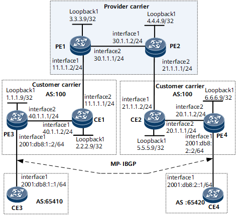
The Level 1 carrier and the Level 2 carrier are in the same AS. The Level 2 carrier provides the BGP/MPLS IPv6 VPN service for its customers, as shown in Figure 1:
PE1 and PE2 are PEs of the Level 1 carrier's backbone.
CE1 and CE2 belong to the Level 2 carrier and access the backbone of Level 1 carrier.
PE3 and PE4 belong to the Level 2 carrier and provide access service for Level 2 carrier's customer.
CE3 and CE4 are the Level 2 carrier's customer.
Configuration Roadmap
The configuration roadmap is as follows:
The two types of routes are exchanged as follows:
Exchange of internal routes of the Level 2 carrier on the backbone network of Level 1 carrier: Configure the Level 2 carrier to access the Level 1 carrier as the Level 1 carrier's CE.
Exchange of external routes of the Level 2 carrier between the PEs of the Level 2 carrier: Set up the MP-IBGP peer relationship between the PEs (PE3 and PE4) of the Level 2 carrier.
Configure the carrier's carrier of the same AS and configure an IGP and LDP between the Level 1 carrier PE and Level 1 carrier CE.
Data Preparation
To configure the carrier's carrier in the same AS, you need the following data:
MPLS LSR IDs of the Level 1 PE and Level 2 PEs and CEs
IGP data
Name of the VPN instance enabled with the IPv4 address family configured on the Level 1 carrier PE, RD and VPN targets
Name of the VPN instance enabled with the IPv6 address family configured on the Level 2 carrier PE, RD and VPN targets
Procedure
- Configure the BGP/MPLS IP VPN on the Level 1 carrier's backbone.
Adopt IS-IS as an IGP, enable LDP between PE1 and PE2, and establish an MP-IBGP peer relationship between them.
# Configure PE1.
<~HUAWEI> system-view
[~HUAWEI] sysname PE1
[*HUAWEI] commit
[~PE1] interface loopback 1
[*PE1-LoopBack1] ip address 3.3.3.9 32
[*PE1-LoopBack1] quit
[*PE1] mpls lsr-id 3.3.3.9
[*PE1] mpls
[*PE1-mpls] quit
[*PE1] mpls ldp
[*PE1-mpls-ldp] quit
[*PE1] isis 1
[*PE1-isis-1] network-entity 10.0000.0000.0004.00
[*PE1-isis-1] quit
[*PE1] interface loopback 1
[*PE1-LoopBack1] isis enable 1
[*PE1-LoopBack1] quit
[*PE1] interface gigabitEthernet 0/1/8
[*PE1-GigabitEthernet0/1/8] ip address 30.1.1.1 24
[*PE1-GigabitEthernet0/1/8] isis enable 1
[*PE1-GigabitEthernet0/1/8] mpls
[*PE1-GigabitEthernet0/1/8] mpls ldp
[*PE1-GigabitEthernet0/1/8] quit
[*PE1] bgp 100
[*PE1-bgp] peer 4.4.4.9 as-number 100
[*PE1-bgp] peer 4.4.4.9 connect-interface loopback 1
[*PE1-bgp] ipv4-family vpnv4
[*PE1-bgp-af-vpnv4] peer 4.4.4.9 enable
[*PE1-bgp-af-vpnv4] commit
[~PE1-bgp-af-vpnv4] quit
[~PE1-bgp] quit

The configuration of PE2 is similar to that of PE1. For configuration details, see Configuration Files in this section.
After completing the configurations, run the display isis peer command to find that the IS-IS neighbor has been set up. Run the display mpls ldp session command on PE1 or PE2 and find that the LDP session has been established successfully. Run the display bgp vpn4 all peer command and find that the BGP peer relationship has been established.
The following example uses the command output on PE1.
[~PE1] display isis peer
                          Peer information for ISIS(1)
  System Id    Interface   Circuit Id    State HoldTime Type   PRI
-------------------------------------------------------------------------------
0000.0000.0005 GigabitEthernet0/1/8    0000000001       Up   29s    L2(L1L2) --
Total Peer(s): 1
[~PE1] display mpls ldp session
2021-04-26 18:58:52.669

 LDP Session(s) in Public Network
 Codes: LAM(Label Advertisement Mode), SsnAge Unit(DDDD:HH:MM)
 An asterisk (*) before a session means the session is being deleted.
 --------------------------------------------------------------------------
 PeerID             Status      LAM  SsnRole  SsnAge       KASent/Rcv
 --------------------------------------------------------------------------
 4.4.4.9:0          Operational DU   Active   0000:00:01   8/8
 --------------------------------------------------------------------------
 TOTAL: 1 Session(s) Found.
[~PE1] display bgp vpnv4 all peer
 BGP local router ID : 3.3.3.9
 Local AS number : 100
 Total number of peers : 1          Peers in established state : 1
  Peer        V  AS  MsgRcvd  MsgSent  OutQ  Up/Down   State    PrefRcv
  4.4.4.9     4 100      162      145     0 02:12:47 Established   0
- Configure Level 2 carrier's network.
Adopt OSPF as the IGP and enable LDP between PE3 and CE1, PE4 and CE2 respectively.
# Configure PE3.
<~HUAWEI> system-view
[~HUAWEI] sysname PE3
[*HUAWEI] commit
[~PE3] interface loopback 1
[*PE3-LoopBack1] ip address 1.1.1.9 32
[*PE3-LoopBack1] quit
[*PE3] mpls lsr-id 1.1.1.9
[*PE3] mpls
[*PE3-mpls] quit
[*PE3] mpls ldp
[*PE3-mpls-ldp] quit
[*PE3] interface gigabitEthernet 0/1/8
[*PE3-GigabitEthernet0/1/8] ip address 40.1.1.1 24
[*PE3-GigabitEthernet0/1/8] mpls
[*PE3-GigabitEthernet0/1/8] mpls ldp
[*PE3-GigabitEthernet0/1/8] quit
[*PE3] ospf 1
[*PE3-ospf-1] area 0
[*PE3-ospf-1-area-0.0.0.0] network 1.1.1.9 0.0.0.0
[*PE3-ospf-1-area-0.0.0.0] network 40.1.1.0 0.0.0.255
[*PE3-ospf-1-area-0.0.0.0] commit
[~PE3-ospf-1-area-0.0.0.0] quit
[~PE3-ospf-1] quit
# Configure CE1.
<~HUAWEI> system-view
[~HUAWEI] sysname CE1
[*HUAWEI] commit
[~CE1] interface loopback 1
[*CE1-LoopBack1] ip address 2.2.2.9 32
[*CE1-LoopBack1] quit
[*CE1] mpls lsr-id 2.2.2.9
[*CE1] mpls
[*CE1-mpls] quit
[*CE1] mpls ldp
[*CE1-mpls-ldp] quit
[*CE1] interface gigabitEthernet 0/1/0
[*CE1-GigabitEthernet0/1/0] ip address 40.1.1.2 24
[*CE1-GigabitEthernet0/1/0] mpls
[*CE1-GigabitEthernet0/1/0] mpls ldp
[*CE1-GigabitEthernet0/1/0] quit
[*CE1] ospf 1
[*CE1-ospf-1] area 0
[*CE1-ospf-1-area-0.0.0.0] network 2.2.2.9 0.0.0.0
[*CE1-ospf-1-area-0.0.0.0] network 40.1.1.0 0.0.0.255
[*CE1-ospf-1-area-0.0.0.0] commit
[~CE1-ospf-1-area-0.0.0.0] quit
[~CE1-ospf-1] quit
After the configuration is complete, PE3 and CE1 can establish LDP and OSPF neighbor relationships.
The configurations of PE4 and CE2 are similar to those of PE3 and CE1. For configuration details, see Configuration Files in this section.
- Configure CEs of the Level 1 carrier to access PEs of the Level 1 carrier.
# Configure PE1.
[~PE1] ip vpn-instance vpn1
[*PE1-vpn-instance-vpn1] ipv4-family
[*PE1-vpn-instance-vpn1-af-ipv4] route-distinguisher 200:1
[*PE1-vpn-instance-vpn1-af-ipv4] apply-label per-route
[*PE1-vpn-instance-vpn1-af-ipv4] vpn-target 1:1 both
[*PE1-vpn-instance-vpn1-af-ipv4] quit
[*PE1-vpn-instance-vpn1] quit
[*PE1] bgp 100
[*PE1-bgp] ipv4-family vpn-instance vpn1
[*PE1-bgp-vpn1] import-route ospf 1
[*PE1-bgp-vpn1] quit
[*PE1-bgp] quit
[*PE1] mpls ldp vpn-instance vpn1
[*PE1-mpls-ldp-vpn-instance-vpn1] quit
[*PE1] ospf 1 vpn-instance vpn1
[*PE1-ospf-1] import-route bgp
[*PE1-ospf-1] quit
[*PE1] interface gigabitEthernet 0/1/0
[*PE1-GigabitEthernet0/1/0] ip binding vpn-instance vpn1
[*PE1-GigabitEthernet0/1/0] ip address 11.1.1.2 24
[*PE1-GigabitEthernet0/1/0] mpls
[*PE1-GigabitEthernet0/1/0] mpls ldp
[*PE1-GigabitEthernet0/1/0] mpls ldp transport-address interface
[*PE1-GigabitEthernet0/1/0] quit
[*PE1] ospf 1
[*PE1-ospf-1] area 0
[*PE1-ospf-1-area-0.0.0.0] network 3.3.3.9 0.0.0.0
[*PE1-ospf-1-area-0.0.0.0] network 11.1.1.0 0.0.0.255
[*PE1-ospf-1-area-0.0.0.0] commit
[~PE1-ospf-1-area-0.0.0.0] quit
[~PE1-ospf-1] quit
# Configure CE1.
[~CE1] interface gigabitEthernet 0/1/8
[*CE1-GigabitEthernet0/1/8] ip address 11.1.1.1 24
[*CE1-GigabitEthernet0/1/8] mpls
[*CE1-GigabitEthernet0/1/8] mpls ldp
[*CE1-GigabitEthernet0/1/8] mpls ldp transport-address interface
[*CE1-GigabitEthernet0/1/8] quit
[*CE1] ospf 1
[*CE1-ospf-1] area 0
[*CE1-ospf-1-area-0.0.0.0] network 11.1.1.0 0.0.0.255
[*CE1-ospf-1-area-0.0.0.0] commit
[~CE1-ospf-1-area-0.0.0.0] quit
[~CE1-ospf-1] quit
After the configuration is complete, PE1 and CE1 can establish LDP and OSPF neighbor relationships.
The configurations of PE2 and CE2 are similar to those of PE1 and CE1. For configuration details, see Configuration Files in this section.
- Configure CEs of the Level 2 carrier to access PEs of the Level 2 carrier.
# Configure CE3.
<~HUAWEI> system-view
[~HUAWEI] sysname CE3
[*HUAWEI] commit
[~CE3] interface gigabitethernet 0/1/0
[*CE3-GigabitEthernet0/1/0] ipv6 enable
[*CE3-GigabitEthernet0/1/0] ipv6 address 2001:db8:1::1 64
[*CE3-GigabitEthernet0/1/0] quit
[*CE3] bgp 65410
[*CE3-bgp] router-id 10.10.10.10
[*CE3-bgp] peer 2001:db8:1::2 as-number 100
[*CE3-bgp] ipv6-family unicast
[*CE3-bgp-af-ipv6] peer 2001:db8:1::2 enable
[*CE3-bgp-af-ipv6] import-route direct
[*CE3-bgp-af-ipv6] commit
[~CE3-bgp-af-ipv6] quit
[~CE3-bgp] quit
# Configure PE3.
[~PE3] ip vpn-instance vpn1
[*PE3-vpn-instance-vpn1] ipv6-family
[*PE3-vpn-instance-vpn1-af-ipv6] route-distinguisher 100:1
[*PE1-vpn-instance-vpn1-af-ipv6] apply-label per-route
[*PE3-vpn-instance-vpn1-af-ipv6] vpn-target 1:1 both
[*PE3-vpn-instance-vpn1-af-ipv6] quit
[*PE3-vpn-instance-vpn1] quit
[*PE3] interface gigabitethernet 0/1/0
[*PE3-GigabitEthernet0/1/0] ipv6 enable
[*PE3-GigabitEthernet0/1/0] ip binding vpn-instance vpn1
[*PE3-GigabitEthernet0/1/0] ipv6 address 2001:db8:1::2 64
[*PE3-GigabitEthernet0/1/0] quit
[*PE3] bgp 100
[*PE3-bgp] ipv6-family vpn-instance vpn1
[*PE3-bgp6-vpn1] peer 2001:db8:1::1 as-number 65410
[*PE3-bgp6-vpn1] import-route direct
[*PE3-bgp6-vpn1] commit
[~PE3-bgp6-vpn1] quit
[~PE3-bgp] quit
The configurations of PE4 and CE4 are similar to those of PE3 and CE3. For configuration details, see Configuration Files in this section.
Then run the display bgp vpnv6 vpn-instance vpn1 peer command on PE3 and PE4, or run the display bgp ipv6 peer command on CE3 and CE4. You can view that the status of the BGP peer relationship between PE3 and CE3, and that between PE4 and CE4 are Established.
- Establish MP-IBGP peers between Level 2 carrier's PEs to exchange VPN routes of Level 2 carrier's CEs.
# Configure PE3.
[~PE3] bgp 100
[*PE3-bgp] peer 6.6.6.9 as-number 100
[*PE3-bgp] peer 6.6.6.9 connect-interface loopback 1
[*PE3-bgp] ipv6-family vpnv6
[*PE3-bgp-af-vpnv6] peer 6.6.6.9 enable
[*PE3-bgp-af-vpnv6] commit
[~PE3-bgp-af-vpnv6] quit
[~PE3-bgp] quit
The configuration of the PE4 is similar to that of the PE3. For configuration details, see Configuration Files in this section.
Then run the display bgp vpnv6 vpn-instance vpn1 peer command on PE3 and PE4. You can view that the MP-IBGP peer relationship between PE3 and PE4 is Established.
- Verify the configuration.
After all the configurations, run the display ip routing-table command on PE1 and PE2 to find that the public routing table on PE1 and PE2 contains only the Level 1 carrier's routes.
[~PE1] display ip routing-table
Route Flags: R - relay, D - download to fib, T - to vpn-instance, B - black hole route
------------------------------------------------------------------------------
Routing Table: Public
         Destinations : 7        Routes : 7
  Destination/Mask  Proto  Pre  Cost       Flags NextHop      Interface
        3.3.3.9/32  Direct 0    0             D  127.0.0.1    LoopBack1
        4.4.4.9/32  ISIS   15   10            D  30.1.1.2     GigabitEthernet0/1/8
       30.1.1.0/24  Direct 0    0             D  30.1.1.1     GigabitEthernet0/1/8
       30.1.1.1/32  Direct 0    0             D  127.0.0.1    GigabitEthernet0/1/8
       30.1.1.2/32  Direct 0    0             D  30.1.1.2     GigabitEthernet0/1/8
      127.0.0.0/8   Direct 0    0             D  127.0.0.1    InLoopBack0
      127.0.0.1/32  Direct 0    0             D  127.0.0.1    InLoopBack0
Run the display ip routing-table vpn-instance command on PE1 and PE2, to find that the VPN routing table contains the internal routes of the Level 2 carrier. The following example uses the command output on PE1.
[~PE1] display ip routing-table vpn-instance vpn1
Route Flags: R - relay, D - download to fib, T - to vpn-instance, B - black hole route
------------------------------------------------------------------------------
Routing Table: vpn1
         Destinations : 11        Routes : 11
  Destination/Mask  Proto  Pre  Cost       Flags NextHop       Interface
        1.1.1.9/32  OSPF   10   2             D  11.1.1.1      GigabitEthernet0/1/0
        2.2.2.9/32  OSPF   10   1             D  11.1.1.1      GigabitEthernet0/1/0
        5.5.5.9/32  IBGP   255  0             RD  4.4.4.9       GigabitEthernet0/1/8
        6.6.6.9/32  IBGP   255  0             RD  4.4.4.9       GigabitEthernet0/1/8
        40.1.1.0/24  OSPF   10   2           D  11.1.1.1     GigabitEthernet0/1/0
       11.1.1.0/24  Direct 0    0             D  11.1.1.1      GigabitEthernet0/1/0
       11.1.1.1/32  Direct 0    0             D  127.0.0.1     GigabitEthernet0/1/0
       11.1.1.2/32  Direct 0    0             D  11.1.1.2      GigabitEthernet0/1/0
        20.1.1.0/24  IBGP    255  0          RD  4.4.4.9      GigabitEthernet0/1/8
       21.1.1.0/24  IBGP    255  0            RD  4.4.4.9       GigabitEthernet0/1/8
Run the display ip routing-table command on CE1 and CE2 to find that the public routing table contains internal routes of the Level 2 carrier. The following example uses the command output on CE1.
[~CE1] display ip routing-table
Route Flags: R - relay, D - download to fib, T - to vpn-instance, B - black hole route
------------------------------------------------------------------------------
Routing Table: vpn1
Routing Table: Public
         Destinations : 15       Routes : 15
  Destination/Mask  Proto  Pre  Cost       Flags  NextHop         Interface
        1.1.1.9/32  OSPF   10   1              D  40.1.1.2        GigabitEthernet0/1/0
        2.2.2.9/32  Direct 0    0              D  127.0.0.1       LoopBack1
        5.5.5.9/32  OSPF   10   3              D  11.1.1.2        GigabitEthernet0/1/8
        6.6.6.9/32  OSPF   10   4              D  11.1.1.2        GigabitEthernet0/1/8
        40.1.1.0/24  Direct 0   0           D  40.1.1.2       GigabitEthernet0/1/0
       40.1.1.1/32  Direct 0    0              D  40.1.1.1        LoopBack1
       40.1.1.2/32  Direct 0    0              D  127.0.0.1       InLoopBack0
       11.1.1.0/24  Direct 0    0              D  11.1.1.1        GigabitEthernet0/1/8
       11.1.1.1/32  Direct 0    0              D  127.0.0.1       GigabitEthernet0/1/8
       11.1.1.2/32  Direct 0    0              D  11.1.1.2        GigabitEthernet0/1/8
        20.1.1.0/24  OSPF   10  4           D  11.1.1.2        GigabitEthernet0/1/8
       21.1.1.0/24  OSPF   10   3              D  11.1.1.2        GigabitEthernet0/1/8
      127.0.0.0/8   Direct 0    0              D  127.0.0.1       InLoopBack0
      127.0.0.1/32  Direct 0    0              D  127.0.0.1       InLoopBack0
Run the display ip routing-table command on PE3 and PE4 to find that the internal routes of the Level 2 carrier are contained in the public routing table. The following example uses the command output on PE3.
[~PE3] display ip routing-table
Route Flags: R - relay, D - download to fib, T - to vpn-instance, B - black hole route
------------------------------------------------------------------------------
Routing Table: Public
         Destinations : 13       Routes : 13
  Destination/Mask  Proto  Pre  Cost       Flags  NextHop         Interface
        1.1.1.9/32  Direct 0    0              D  127.0.0.1       LoopBack1
        2.2.2.9/32  OSPF   10   1              D  40.1.1.2        GigabitEthernet0/1/8
        5.5.5.9/32  OSPF   10   4              D  40.1.1.2        GigabitEthernet0/1/8
        6.6.6.9/32  OSPF   10   5              D  40.1.1.2        GigabitEthernet0/1/8
        40.1.1.0/24  Direct 0   0           D  40.1.1.1        GigabitEthernet0/1/8
       40.1.1.1/32  Direct 0    0              D  127.0.0.1       GigabitEthernet0/1/8
       40.1.1.2/32  Direct 0    0              D  40.1.1.2        GigabitEthernet0/1/8
       11.1.1.0/24  OSPF   10   2              D  40.1.1.2        GigabitEthernet0/1/8
        20.1.1.0/24  OSPF 10   5            D  40.1.1.2       GigabitEthernet0/1/8
       20.1.1.1/32  EBGP   255   0            RD  6.6.6.9         GigabitEthernet0/1/8
       21.1.1.0/24  OSPF   10   4              D  40.1.1.2        GigabitEthernet0/1/8
      127.0.0.0/8   Direct 0    0              D  127.0.0.1       InLoopBack0
      127.0.0.1/32  Direct 0    0              D  127.0.0.1       InLoopBack0
Run the display ipv6 routing-table vpn-instance command on PE3 and PE4 to find that the routes of the remote CEs, that is, the external routes of the Level 2 carrier, are contained in the VPN routing table. The following example uses the command output on PE3.
[~PE3] display ipv6 routing-table vpn-instance vpn1
Routing Table : vpn1
         Destinations : 4        Routes : 4

 Destination  : 2001:db8:1::                    PrefixLength : 64
 NextHop      : 2001:db8:1::2                   Preference   : 0
 Cost         : 0                               Protocol     : Direct
 RelayNextHop : ::                              TunnelID     : 0x0
 Interface    : GigabitEthetnet0/1/0            Flags        : D

 Destination  : 2001:db8:1::2                   PrefixLength : 128
 NextHop      : ::1                             Preference   : 0
 Cost         : 0                               Protocol     : Direct
 RelayNextHop : ::                              TunnelID     : 0x0
 Interface    : GigabitEthetnet0/1/0            Flags        : D

 Destination  : 2001:db8:2::                    PrefixLength : 64
 NextHop      : ::FFFF:6.6.6.9                  Preference   : 255
 Cost         : 0                               Protocol     : EBGP
 RelayNextHop : ::                              TunnelID     : 0xf0010056
 Interface    : NULL0                           Flags        : RD

 Destination  : FE80::                          PrefixLength : 10
 NextHop      : ::                              Preference   : 0
 Cost         : 0                               Protocol     : Direct
 RelayNextHop : ::                              TunnelID     : 0x0
 Interface    : NULL0                           Flags        : D
PE3 and PE4 can ping through each other.
[~PE3] ping 20.1.1.2
  PING 20.1.1.2: 56  data bytes, press CTRL_C to break
    Reply from 20.1.1.2: bytes=56 Sequence=1 ttl=251 time=125 ms
    Reply from 20.1.1.2: bytes=56 Sequence=2 ttl=251 time=109 ms
    Reply from 20.1.1.2: bytes=56 Sequence=3 ttl=251 time=110 ms
    Reply from 20.1.1.2: bytes=56 Sequence=4 ttl=251 time=94 ms
    Reply from 20.1.1.2: bytes=56 Sequence=5 ttl=251 time=109 ms

  --- 20.1.1.2 ping statistics ---
    5 packet(s) transmitted
    5 packet(s) received
    0.00% packet loss
    round-trip min/avg/max = 94/109/125 ms
CE3 and CE4 can ping through each other.
[~CE3] ping ipv6 2001:db8:2::1
  PING 2001:db8:2::1 : 56  data bytes, press CTRL_C to break
    Reply from 2001:db8:2::1
    bytes=56 Sequence=1 hop limit=62  time = 141 ms
    Reply from 2001:db8:2::1
    bytes=56 Sequence=2 hop limit=62  time = 157 ms
    Reply from 2001:db8:2::1
    bytes=56 Sequence=3 hop limit=62  time = 141 ms
    Reply from 2001:db8:2::1
    bytes=56 Sequence=4 hop limit=62  time = 141 ms
    Reply from 2001:db8:2::1
    bytes=56 Sequence=5 hop limit=62  time = 141 ms

  --- 2001:db8:2::1 ping statistics ---
    5 packet(s) transmitted
    5 packet(s) received
    0.00% packet loss
round-trip min/avg/max = 141/144/157 ms
Configuration Files
CE3 configuration file
#
 sysname CE3
#
 ipv6
#
interface GigabitEthernet0/1/0
 undo shutdown
 ipv6 enable
 ipv6 address 2001:db8:1::1/64
#
bgp 65410
 router-id 10.10.10.10
 peer 2001:db8:1::2 as-number 100
 #
 ipv6-family unicast
  undo synchronization
  import-route direct
  peer 2001:db8:1::2 enable
#
return
PE3 configuration file
#
 sysname PE3
#
ip vpn-instance vpn1
 ipv6-family
  route-distinguisher 100:1
  apply-label per-route
  vpn-target 1:1 export-extcommunity
  vpn-target 1:1 import-extcommunity
#
 ipv6
#
 mpls lsr-id 1.1.1.9
 mpls
#
mpls ldp
#
interface GigabitEthernet0/1/0
 undo shutdown
 ip binding vpn-instance vpn1
 ipv6 enable
 ipv6 address 2001:db8:1::2/64
#
interface GigabitEthernet0/1/8
 undo shutdown
 ip address 40.1.1.1 255.255.255.0
 mpls
 mpls ldp
#
interface LoopBack1
 ip address 1.1.1.9 255.255.255.255
#
bgp 100
 peer 6.6.6.9 as-number 100
 peer 6.6.6.9 connect-interface LoopBack1
 #
 ipv4-family unicast
  undo synchronization
  import-route direct
  peer 6.6.6.9 enable
 #
 ipv6-family vpnv6
  policy vpn-target
  peer 6.6.6.9 enable
 #
 ipv6-family vpn-instance vpn1
  peer 2001:db8:1::1 as-number 65410
  import-route direct
#
ospf 1
 area 0.0.0.0
  network 1.1.1.9 0.0.0.0
  network 40.1.1.0 0.0.0.255
#
return
CE1 configuration file
#
 sysname CE1
#
 mpls lsr-id 2.2.2.9
 mpls
#
mpls ldp
#
interface GigabitEthernet0/1/0
 undo shutdown
 ip address 40.1.1.2 255.255.255.0
 mpls
 mpls ldp
#
interface GigabitEthernet0/1/8
 undo shutdown
 ip address 11.1.1.1 255.255.255.0
 mpls
 mpls ldp
 mpls ldp transport-address interface
#
interface LoopBack1
 ip address 2.2.2.9 255.255.255.255
#
ospf 1
 area 0.0.0.0
  network 2.2.2.9 0.0.0.0
  network 11.1.1.0 0.0.0.255
  network 40.1.1.0 0.0.0.255
#
return
PE1 configuration file
#
 sysname PE1
#
ip vpn-instance vpn1
 ipv4-family
  route-distinguisher 200:1
  apply-label per-route
  vpn-target 1:1 export-extcommunity
  vpn-target 1:1 import-extcommunity
#
 mpls lsr-id 3.3.3.9
 mpls
#
mpls ldp
#
mpls ldp vpn-instance vpn1
#
isis 1
 network-entity 10.0000.0000.0004.00
#
ospf 1 vpn-instance vpn1
 import-route bgp
 area 0.0.0.0
  network 3.3.3.9 0.0.0.0
  network 11.1.1.0 0.0.0.255
#
interface GigabitEthernet0/1/0
 undo shutdown
 ip binding vpn-instance vpn1
 ip address 11.1.1.2 255.255.255.0
 mpls
 mpls ldp
#
interface GigabitEthernet0/1/8
 undo shutdown
 ip address 30.1.1.1 255.255.255.0
 isis enable 1
 mpls
 mpls ldp
#
interface LoopBack1
 ip address 3.3.3.9 255.255.255.255
 isis enable 1
#
bgp 100
 peer 4.4.4.9 as-number 100
 peer 4.4.4.9 connect-interface LoopBack1
 #
 ipv4-family unicast
  undo synchronization
  peer 4.4.4.9 enable
 #
 ipv4-family vpnv4
  policy vpn-target
  peer 4.4.4.9 enable
 #
 ipv4-family vpn-instance vpn1
  import-route ospf 1
#
return
PE2 configuration file
#
 sysname PE2
#
ip vpn-instance vpn1
 ipv4-family
  route-distinguisher 200:2
  apply-label per-route
  vpn-target 1:1 export-extcommunity
  vpn-target 1:1 import-extcommunity
#
 mpls lsr-id 4.4.4.9
 mpls
#
mpls ldp
#
mpls ldp vpn-instance vpn1
#
isis 1
 network-entity 10.0000.0000.0005.00
#
ospf 1 vpn-instance vpn1
 import-route bgp
 area 0.0.0.0
  network 4.4.4.9 0.0.0.0
  network 21.1.1.0 0.0.0.255
#
interface GigabitEthernet0/1/0
 undo shutdown
 ip address 30.1.1.2 255.255.255.0
 isis enable 1
 mpls
 mpls ldp
#
interface GigabitEthernet0/1/8
 undo shutdown
 ip binding vpn-instance vpn1
 ip address 21.1.1.1 255.255.255.0
 mpls
 mpls ldp
#
interface LoopBack1
 ip address 4.4.4.9 255.255.255.255
 isis enable 1
#
bgp 100
 peer 3.3.3.9 as-number 100
 peer 3.3.3.9 connect-interface LoopBack1
 #
 ipv4-family unicast
  undo synchronization
  peer 3.3.3.9 enable
 #
 ipv4-family vpnv4
  policy vpn-target
  peer 3.3.3.9 enable
#
 ipv4-family vpn-instance vpn1
  import-route ospf 1
#
return
CE2 configuration file
#
 sysname CE2
#
 mpls lsr-id 5.5.5.9
 mpls
#
mpls ldp
#
interface GigabitEthernet0/1/0
 undo shutdown
 ip address 21.1.1.2 255.255.255.0
 mpls
 mpls ldp
 mpls ldp transport-address interface
#
interface GigabitEthernet0/1/8
 undo shutdown
 ip address 20.1.1.1 255.255.255.0
 mpls
 mpls ldp
#
interface LoopBack1
 ip address 5.5.5.9 255.255.255.255
#
ospf 1
 area 0.0.0.0
  network 5.5.5.9 0.0.0.0
  network 20.1.1.0 0.0.0.255
  network 21.1.1.0 0.0.0.255
#
return
PE4 configuration file
#
 sysname PE4
#
ip vpn-instance vpn1
 ipv6-family
  route-distinguisher 100:2
  apply-label per-route
  vpn-target 1:1 export-extcommunity
  vpn-target 1:1 import-extcommunity
#
 ipv6
#
 mpls lsr-id 6.6.6.9
 mpls
#
mpls ldp
#
interface GigabitEthernet0/1/0
 undo shutdown
 ip binding vpn-instance vpn1
 ipv6 enable
 ipv6 address 2001:db8:2::2/64
#
interface GigabitEthernet0/1/8
 undo shutdown
 ip address 20.1.1.2 255.255.255.0
 mpls
 mpls ldp
#
interface LoopBack1
 ip address 6.6.6.9 255.255.255.255
#
bgp 100
 peer 1.1.1.9 as-number 100
 peer 1.1.1.9 connect-interface LoopBack1
 #
 ipv4-family unicast
  undo synchronization
  import-route direct
  peer 1.1.1.9 enable
 #
 ipv6-family vpnv6
  policy vpn-target
  peer 1.1.1.9 enable
#
ospf 1
 area 0.0.0.0
  network 6.6.6.9 0.0.0.0
  network 20.1.1.0 0.0.0.255
#
 ipv6-family vpn-instance vpn1
  peer 2001:db8:2::1 as-number 65420
  import-route direct
#
return
CE4 configuration file
#
 sysname CE4
#
 ipv6
#
interface GigabitEthernet0/1/0
 undo shutdown
 ipv6 enable
 ipv6 address 2001:db8:2::1/64
#
bgp 65420
 router-id 20.20.20.20
 peer 2001:db8:2::2 as-number 100
 #
 ipv6-family unicast
  undo synchronization
  import-route direct
  peer 2001:db8:2::2 enable
#
return