Example for Configuring Basic VPN Dual-Stack Access
This section provides an example for configuring basic VPN dual-stack access. After both IPv4 and IPv6 address families are configured in VPN instances, the interfaces bound to the VPN instances can support not only IPv4 VPN access but also IPv6 VPN access. This implementation greatly improves the feasibility of the transition from IPv4 to IPv6.
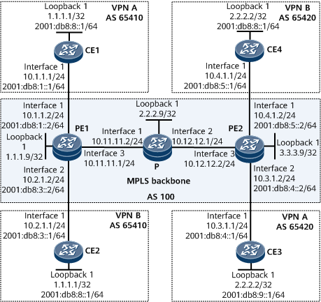
Networking Requirements
On the network shown in Figure 1, CE1 and CE3 belong to VPN A, and CE2 and CE4 belong to VPN B. CE1 and CE2 need to communicate with CE3 and CE4, respectively, using both IPv4 and IPv6 routes over the public network, but the public network does not need to be aware of routing information within the sites.
BGP and BGP4+ are required between PE1 and CE1, and between PE2 and CE4.
Static routes are required between PE1 and CE2.
OSPF and OSPFv3 are required between PE2 and CE3.

Configuration Roadmap
The configuration roadmap is as follows:
Configure an IGP on the IPv4 backbone network to implement PE interworking.
Configure MPLS and MPLS LDP on each PE and the P and establish an LDP LSP between PEs.
Configure MP-IBGP on PE1 and PE2 so that the PEs can use BGP to exchange IPv4 and IPv6 VPN routes.
Configure VPN instances that support the IPv4 and IPv6 address families on each PE and bind the PE interfaces that connect to CEs to the VPN instances.
Configure IPv4 and IPv6 routing protocols between PEs and CEs so that PEs and CEs can exchange IPv4 and IPv6 routes.
Data Preparation
To complete the configuration, you need the following data:
AS numbers of PEs and CEs
VPN instance names: vpna and vpnb
Attributes of the VPN instance IPv4 and IPv6 address families, such as the RDs and VPN targets
Procedure
- Assign an IPv4 or IPv6 address to each involved interface on devices.
# Assign IPv4 and IPv6 addresses to interfaces on CE1.
<CE1> system-view
[~CE1] interface gigabitethernet 0/1/0
[~CE1-GigabitEthernet0/1/0] ip address 10.1.1.1 24
[*CE1-GigabitEthernet0/1/0] ipv6 enable
[*CE1-GigabitEthernet0/1/0] ipv6 address 2001:db8:1::1 64
[*CE1-GigabitEthernet0/1/0] commit
[~CE1-GigabitEthernet0/1/0] quit
The configurations of CE2, CE3, CE4, P, PE1, and PE2 are similar to the configuration of CE1. For configuration details, see Configuration Files in this section.
- Configure an IGP over the IPv4 backbone network to implement communication between PEs. IS-IS is used in this example.
# Configure PE1.
[~PE1] isis 1
[*PE1-isis-1] network-entity 10.1111.1111.1111.00
[*PE1-isis-1] quit
[*PE1] interface gigabitEthernet 0/1/16
[*PE1-GigabitEthernet0/1/16] isis enable 1
[*PE1-GigabitEthernet0/1/16] quit
[*PE1] interface loopback 1
[*PE1-LoopBack1] isis enable 1
[*PE1-LoopBack1] quit
[*PE1] commit
The configurations of the P and PE2 are similar to the configuration of PE1. For configuration details, see Configuration Files in this section.
After the configuration is complete, PE1, PE2, and the P can learn routes, including the routes to loopback interfaces, from one another. You can run the display ip routing-table command to view the routes. The command output on PE1 is used as an example.
[~PE1] display ip routing-table
Route Flags: R - relay, D - download to fib, T - to vpn-instance, B - black hole route
------------------------------------------------------------------------------
Routing Table: _public_
         Destinations : 11        Routes : 11

Destination/Mask    Proto   Pre  Cost      Flags NextHop         Interface

1.1.1.9/32          Direct  0    0           D   127.0.0.1       InLoopBack0
2.2.2.9/32         ISIS-L2 15   10          D   10.11.11.2      GigabitEthernet0/1/16
3.3.3.9/32         ISIS-L2 15   20          D   10.11.11.2      GigabitEthernet0/1/16
127.0.0.0/8         Direct  0    0           D   127.0.0.1       InLoopBack0
127.0.0.1/32        Direct  0    0           D   127.0.0.1       InLoopBack0
127.255.255.255/32  Direct  0    0           D   127.0.0.1       InLoopBack0
10.11.11.0/24       Direct  0    0           D   10.11.11.1      GigabitEthernet0/1/16
10.11.11.1/32       Direct  0    0           D   127.0.0.1       GigabitEthernet0/1/16
10.11.11.255/32     Direct  0    0           D   127.0.0.1       GigabitEthernet0/1/16
10.12.12.0/24       ISIS-L2 15   20          D   10.11.11.2      GigabitEthernet0/1/16
255.255.255.255/32  Direct  0    0           D   127.0.0.1       InLoopBack0
- Enable MPLS and MPLS LDP on each device and device interface over the IPv4 backbone network. Create an LDP LSP between PE1 and PE2.
# Enable MPLS and MPLS LDP on PE1.
[~PE1] mpls lsr-id 1.1.1.9
[*PE1] mpls
[*PE1-mpls] quit
[*PE1] mpls ldp
[*PE1-mpls-ldp] quit
[*PE1] interface gigabitEthernet 0/1/16
[*PE1-GigabitEthernet0/1/16] mpls
[*PE1-GigabitEthernet0/1/16] mpls ldp
[*PE1-GigabitEthernet0/1/16] quit
[*PE1] commit
The configurations of the P and PE2 are similar to the configuration of PE1. For configuration details, see Configuration Files in this section.
After completing the configurations, an LDP LSP can be established between PE1 and PE2. Then, run the display mpls ldp lsp command. The command output shows that an LDP LSP has been successfully established on each device. The command output on PE1 is used as an example.
[~PE1] display mpls ldp lsp
 LDP LSP Information
 -------------------------------------------------------------------------------
 Flag after Out IF: (I) - RLFA Iterated LSP, (I*) - Normal and RLFA Iterated LSP
 -------------------------------------------------------------------------------
 DestAddress/Mask   In/OutLabel    UpstreamPeer    NextHop          OutInterface
 -------------------------------------------------------------------------------
 1.1.1.9/32         3/NULL         2.2.2.9         127.0.0.1       InLoop0
*1.1.1.9/32         Liberal/1024                   DS/2.2.2.9
 2.2.2.9/32         NULL/3         -               10.11.11.2       GE0/1/16
 2.2.2.9/32         1024/3         2.2.2.9         10.11.11.2       GE0/1/16
 3.3.3.9/32         NULL/1025      -               10.11.11.2       GE0/1/16
 3.3.3.9/32         1025/1025      2.2.2.9         10.11.11.2       GE0/1/16
 -------------------------------------------------------------------------------
 TOTAL: 5 Normal LSP(s) Found.
 TOTAL: 1 Liberal LSP(s) Found.
 TOTAL: 0 Frr LSP(s) Found.
 An asterisk (*) before an LSP means the LSP is not established
 An asterisk (*) before a Label means the USCB or DSCB is stale
 An asterisk (*) before an UpstreamPeer means the session is stale
 An asterisk (*) before a DS means the session is stale
 An asterisk (*) before a NextHop means the LSP is FRR LSP
- On each PE, configure a VPN instance that supports the IPv4 and IPv6 address families and bind the PE interfaces that connect to CEs to the VPN instances.
# Configure a VPN instance named vpna on PE1 to support the IPv4 and IPv6 address families.
[~PE1] ip vpn-instance vpna
[*PE1-vpn-instance-vpna] ipv4-family
[*PE1-vpn-instance-vpna-af-ipv4] route-distinguisher 200:1
[*PE1-vpn-instance-vpna-af-ipv4] vpn-target 66:77 both
[*PE1-vpn-instance-vpna-af-ipv4] quit
[*PE1-vpn-instance-vpna] ipv6-family
[*PE1-vpn-instance-vpna-af-ipv6] route-distinguisher 100:1
[*PE1-vpn-instance-vpna-af-ipv6] vpn-target 22:22 export-extcommunity
[*PE1-vpn-instance-vpna-af-ipv6] vpn-target 33:33 import-extcommunity
[*PE1-vpn-instance-vpna-af-ipv6] quit
[*PE1-vpn-instance-vpna] quit
[*PE1] commit
# Bind the interface that directly connects PE1 to CE1 to the VPN instance named vpna.
[~PE1] interface gigabitethernet 0/1/0
[~PE1-GigabitEthernet0/1/0] ip binding vpn-instance vpna
[*PE1-GigabitEthernet0/1/0] ip address 10.1.1.2 24
[*PE1-GigabitEthernet0/1/0] ipv6 enable
[*PE1-GigabitEthernet0/1/0] ipv6 address 2001:db8:1::2 64
[*PE1-GigabitEthernet0/1/0] quit
[*PE1] commit
# Configure a VPN instance named vpnb on PE1 to support the IPv4 and IPv6 address families.
[~PE1] ip vpn-instance vpnb
[*PE1-vpn-instance-vpnb] ipv4-family
[*PE1-vpn-instance-vpnb-af-ipv4] route-distinguisher 200:3
[*PE1-vpn-instance-vpnb-af-ipv4] vpn-target 88:99 both
[*PE1-vpn-instance-vpnb-af-ipv4] quit
[*PE1-vpn-instance-vpnb] ipv6-family
[*PE1-vpn-instance-vpnb-af-ipv6] route-distinguisher 100:3
[*PE1-vpn-instance-vpnb-af-ipv6] vpn-target 44:44 export-extcommunity
[*PE1-vpn-instance-vpnb-af-ipv6] vpn-target 55:55 import-extcommunity
[*PE1-vpn-instance-vpnb-af-ipv6] quit
[*PE1-vpn-instance-vpnb] quit
[*PE1] commit
# Bind the interface that directly connects PE1 to CE2 to the VPN instance named vpnb.
[~PE1] interface gigabitethernet 0/1/8
[~PE1-GigabitEthernet0/1/8] ip binding vpn-instance vpnb
[*PE1-GigabitEthernet0/1/8] ip address 10.2.1.2 24
[*PE1-GigabitEthernet0/1/8] ipv6 enable
[*PE1-GigabitEthernet0/1/8] ipv6 address 2001:db8:3::2 64
[*PE1-GigabitEthernet0/1/8] quit
[*PE1] commit
The configuration of PE2 is similar to the configuration of PE1. For configuration details, see Configuration Files in this section.
After the configuration is complete, run the display ip vpn-instance verbose command on each PE to view information about the VPN instances. The command output shows that each PE can ping its connected CE. The command output on PE1 is used as an example.
[~PE1] display ip vpn-instance verbose
 Total VPN-Instances configured      : 3
 Total IPv4 VPN-Instances configured : 3
 Total IPv6 VPN-Instances configured : 2

 VPN-Instance Name and ID : __dcn_vpn__, 2
  Interfaces : LoopBack2147483647
 Address family ipv4
  Create date : 2020-10-09 07:25:13+00:00
  Up time : 9 days, 20 hours, 11 minutes and 54 seconds
  Vrf Status : UP
  Label Policy : label per instance
  Per-Instance Label : NULL
  The diffserv-mode Information is : uniform
  The ttl-mode Information is : pipe

 VPN-Instance Name and ID : vpna, 4
  Interfaces : GigabitEthernet0/1/0
 Address family ipv4
  Create date : 2020-10-19 02:12:42+00:00
  Up time : 0 days, 01 hours, 24 minutes and 25 seconds
  Vrf Status : UP
  Route Distinguisher : 200:1
  Export VPN Targets : 66:77
  Import VPN Targets : 66:77
  Label Policy : label per instance
  Per-Instance Label : 48123
  The diffserv-mode Information is : uniform
  The ttl-mode Information is : pipe
 Address family ipv6
  Create date : 2020-10-19 02:14:20+00:00
  Up time : 0 days, 01 hours, 22 minutes and 47 seconds
  Vrf Status : UP
  Route Distinguisher : 100:1
  Export VPN Targets : 22:22
  Import VPN Targets : 33:33
  Label Policy : label per instance
  Per-Instance Label : 48121
  The diffserv-mode Information is : uniform
  The ttl-mode Information is : pipe

 VPN-Instance Name and ID : vpnb, 5
  Interfaces : GigabitEthernet0/1/8
 Address family ipv4
  Create date : 2020-10-19 02:16:30+00:00
  Up time : 0 days, 01 hours, 20 minutes and 37 seconds
  Vrf Status : UP
  Route Distinguisher : 200:3
  Export VPN Targets : 88:99
  Import VPN Targets : 88:99
  Label Policy : label per instance
  Per-Instance Label : 48124
  The diffserv-mode Information is : uniform
  The ttl-mode Information is : pipe
 Address family ipv6
  Create date : 2020-10-19 02:16:30+00:00
  Up time : 0 days, 01 hours, 20 minutes and 38 seconds
  Vrf Status : UP
  Route Distinguisher : 100:3
  Export VPN Targets : 44:44
  Import VPN Targets : 55:55
  Label Policy : label per instance
  Per-Instance Label : 48122
  The diffserv-mode Information is : uniform
  The ttl-mode Information is : pipe
[~PE1] ping ip -vpn-instance vpna 10.1.1.1
  PING 10.1.1.1: 56  data bytes, press CTRL_C to break
    Reply from 10.1.1.1: bytes=56 Sequence=1 ttl=255 time=968 ms
    Reply from 10.1.1.1: bytes=56 Sequence=2 ttl=255 time=9 ms
    Reply from 10.1.1.1: bytes=56 Sequence=3 ttl=255 time=7 ms
    Reply from 10.1.1.1: bytes=56 Sequence=4 ttl=255 time=6 ms
    Reply from 10.1.1.1: bytes=56 Sequence=5 ttl=255 time=8 ms

  --- 10.1.1.1 ping statistics ---
    5 packet(s) transmitted
    5 packet(s) received
    0.00% packet loss
    round-trip min/avg/max = 6/199/968 ms
[~PE1] ping ipv6 vpn-instance vpna 2001:db8:1::1
  PING 2001:DB8:1::1 : 56  data bytes, press CTRL_C to break
    Reply from 2001:DB8:1::1
    bytes=56 Sequence=1 hop limit=64 time=311 ms
    Reply from 2001:DB8:1::1
    bytes=56 Sequence=2 hop limit=64 time=9 ms
    Reply from 2001:DB8:1::1
    bytes=56 Sequence=3 hop limit=64 time=12 ms
    Reply from 2001:DB8:1::1
    bytes=56 Sequence=4 hop limit=64 time=11 ms
    Reply from 2001:DB8:1::1
    bytes=56 Sequence=5 hop limit=64 time=7 ms

  --- 2001:DB8:1::1 ping statistics---
    5 packet(s) transmitted
    5 packet(s) received
    0.00% packet loss
    round-trip min/avg/max=7/70/311 ms
- Establish VPNv4 and VPNv6 peer relationships between PEs.
# Configure PE1.
[~PE1] bgp 100
[*PE1-bgp] peer 3.3.3.9 as-number 100
[*PE1-bgp] peer 3.3.3.9 connect-interface loopback 1
[*PE1-bgp] ipv4-family vpnv4
[*PE1-bgp-af-vpnv4] peer 3.3.3.9 enable
[*PE1-bgp] ipv6-family vpnv6
[*PE1-bgp-af-vpnv6] peer 3.3.3.9 enable
[*PE1-bgp-af-vpnv6] quit
[*PE1-bgp] quit
[*PE1] commit
# Configure PE2.
[~PE2] bgp 100
[*PE2-bgp] peer 1.1.1.9 as-number 100
[*PE2-bgp] peer 1.1.1.9 connect-interface loopback 1
[*PE2-bgp] ipv4-family vpnv4
[*PE2-bgp-af-vpnv4] peer 1.1.1.9 enable
[*PE2-bgp] ipv6-family vpnv6
[*PE2-bgp-af-vpnv6] peer 1.1.1.9 enable
[*PE2-bgp-af-vpnv6] quit
[*PE2-bgp] quit
[*PE2] commit
After the configurations are complete, run the display bgp vpnv4 all peer and display bgp vpnv6 all peer commands on the PEs to check whether VPNv4 and VPNv6 peer relationships are established. The command output on PE1 is used as an example.
[~PE1] display bgp vpnv4 all peer
 BGP local router ID : 1.1.1.9
 Local AS number : 100
 Total number of peers : 1                 Peers in established state : 1

  Peer                             V          AS  MsgRcvd  MsgSent  OutQ  Up/Down       State  PrefRcv
  3.3.3.9                          4         100       32       36     0 00:22:36 Established        0
[~PE1] display bgp vpnv6 all peer
 Local AS number : 100
 Total number of peers : 1                 Peers in established state : 1

  Peer                             V          AS  MsgRcvd  MsgSent  OutQ  Up/Down       State  PrefRcv
  3.3.3.9                          4         100       35       39     0 00:25:09 Established        2
The command output shows that the status of VPNv4 and VPNv6 peer relationships is Established, indicating that VPNv4 and VPNv6 peer relationships have been established between PE1 and PE2.
- Configure BGP4 and BGP4+ on PE1 and CE1.
# Configure EBGP on PE1.
[~PE1] bgp 100
[*PE1-bgp] ipv4-family vpn-instance vpna
[*PE1-bgp-vpna] peer 10.1.1.1 as-number 65410
[*PE1-bgp-vpna] quit
[*PE1-bgp] ipv6-family vpn-instance vpna
[*PE1-bgp-6-vpna] peer 2001:db8:1::1 as-number 65410
[*PE1-bgp-6-vpna] quit
[*PE1-bgp] quit
[*PE1] commit
# Configure EBGP on CE1.
[~CE1] bgp 65410
[*CE1-bgp] router-id 10.10.10.10
[*CE1-bgp] peer 10.1.1.2 as-number 100
[*CE1-bgp] ipv4-family unicast
[*CE1-bgp-af-ipv4] network 10.1.1.0 24
[*CE1-bgp-af-ipv4] peer 10.1.1.2 enable
[*CE1-bgp-af-ipv4] import-route direct
[*CE1-bgp-af-ipv4] quit
[*CE1-bgp] peer 2001:db8:1::2 as-number 100
[*CE1-bgp] ipv6-family unicast
[*CE1-bgp-af-ipv6] network 2001:db8:1:: 64
[*CE1-bgp-af-ipv6] peer 2001:db8:1::2 enable
[*CE1-bgp-af-ipv6] import-route direct
[*CE1-bgp-af-ipv6] quit
[*CE1-bgp] quit
[*CE1] commit
The configuration of the EBGP relationship between PE2 and CE4 is similar to the configuration of the EBGP relationship between PE1 and CE1. For configuration details, see Configuration Files in this section.
After the preceding configurations are complete, run the display bgp vpnv4 vpn-instance vpn-instance-name peer and display bgp vpnv6 vpn-instance vpn-instance-name peer commands on the PEs to check whether the BGP peer relationships are established. The following example uses the command output on PE1.
[~PE1] display bgp vpnv4 vpn-instance vpna peer
 BGP local router ID : 1.1.1.9
 Local AS number : 100
 Total number of peers : 1                 Peers in established state : 1

 VPN-Instance vpna, Router ID 1.1.1.9:
  Peer                             V          AS  MsgRcvd  MsgSent  OutQ  Up/Down       State  PrefRcv
  10.1.1.1                         4       65410       98       95     0 01:21:55 Established        2
[~PE1] display bgp vpnv6 vpn-instance vpna peer
 BGP local router ID : 1.1.1.9
 Local AS number : 100
 Total number of peers : 1                 Peers in established state : 1

  VPN-Instance vpna, Router ID 1.1.1.9:
  Peer                             V          AS  MsgRcvd  MsgSent  OutQ  Up/Down       State  PrefRcv
  2001:DB8:1::1                    4       65410      298      301     0 04:17:25 Established        3
- Configure static routes between PE1 and CE2.
# Configure IPv4 and IPv6 static routes for the VPN instance vpnb on PE1 and import the routes to the routing tables of the BGP-VPN instance IPv4 and IPv6 address families.
[~PE1] ip route-static vpn-instance vpnb 1.1.1.1 32 10.2.1.1
[~PE1] ipv6 route-static vpn-instance vpnb 2001:db8:8:: 64 2001:db8:3::1
[*PE1] bgp 100
[*PE1-bgp] ipv4-family vpn-instance vpnb
[*PE1-bgp4-vpnb] import-route static
[*PE1-bgp4-vpnb] quit
[*PE1-bgp] ipv6-family vpn-instance vpnb
[*PE1-bgp6-vpnb] import-route static
[*PE1-bgp6-vpnb] quit
[*PE1-bgp] quit
[*PE1] commit
# Configure IPv4 and IPv6 default routes on CE2.
[~CE2] ip route-static 0.0.0.0 0 10.2.1.2
[*CE2] ipv6 route-static :: 0 2001:db8:3::2
[*CE2] commit
- Configure OSPF and OSPFv3 between PE2 and CE3.
# Configure OSPF and OSPFv3 on PE2.
[~PE2] ospf 1 vpn-instance vpna
[*PE2-ospf-1] area 0.0.0.0
[*PE2-ospf-1-area 0.0.0.0] network 3.3.3.9 0.0.0.0
[*PE2-ospf-1-area 0.0.0.0] network 10.3.1.0 0.0.0.255
[*PE2-ospf-1-area 0.0.0.0] quit
[*PE2-ospf-1] import-route bgp
[*PE2-ospf-1] quit
[~PE2] ospfv3 1 vpn-instance vpna
[*PE2-ospfv3-1] router-id 10.10.11.11
[*PE2-ospfv3-1] area 0.0.0.0
[*PE2-ospfv3-1-area 0.0.0.0] quit
[*PE2-ospfv3-1] import-route bgp
[*PE2-ospfv3-1] quit
[*PE2] interface gigabitethernet 0/1/8
[*PE2-Gigabitethernet 0/1/8] ospfv3 1 area 0
[*PE2-Gigabitethernet 0/1/8] quit
[*PE2] commit
# Import OSPF and OSPFv3 routes to the BGP routing table on PE2.
[~PE2] bgp 100
[*PE2-bgp] ipv4-family vpn-instance vpna
[*PE2-bgp4-vpna] import-route ospf 1
[*PE2-bgp4-vpna] quit
[*PE2-bgp] ipv6-family vpn-instance vpna
[*PE2-bgp-6-vpna] import-route ospfv3 1
[*PE2-bgp-6-vpna] quit
[*PE2-bgp] quit
[*PE2] commit
# Configure OSPF and OSPFv3 on CE3.
[~CE3] ospf 1
[*CE3-ospf-1] area 0.0.0.0
[*CE3-ospf-1-area 0.0.0.0] network 2.2.2.2 0.0.0.0
[*CE3-ospf-1-area 0.0.0.0] network 10.3.1.0 0.0.0.255
[*CE3-ospf-1-area 0.0.0.0] quit
[*CE3-ospf-1] quit
[~CE3] ospfv3 1
[*CE3-ospfv3-1] router-id 22.22.22.22
[*CE3-ospfv3-1] area 0.0.0.0
[*CE3-ospfv3-1-area 0.0.0.0] quit
[*CE3-ospfv3-1] quit
[*CE3] interface gigabitethernet 0/1/0
[*CE3-GigabitEthernet0/1/0] ospfv3 1 area 0
[*CE3-GigabitEthernet0/1/0] quit
[*CE3] interface LoopBack 1
[*CE3-LoopBack1] ospfv3 1 area 0
[*CE3-LoopBack1] quit
[*CE3] commit
- Verify the configuration.
After the configurations are complete, a ping (with the source address specified) between CE1 and CE3, and between CE2 and CE4 can succeed. The command output on CE1 is used as an example.
[~CE1] ping ip -a 1.1.1.1 2.2.2.2
  PING 2.2.2.2: 56  data bytes, press CTRL_C to break
    Reply from 2.2.2.2: bytes=56 Sequence=1 ttl=253 time=45 ms
    Reply from 2.2.2.2: bytes=56 Sequence=2 ttl=253 time=28 ms
    Reply from 2.2.2.2: bytes=56 Sequence=3 ttl=253 time=35 ms
    Reply from 2.2.2.2: bytes=56 Sequence=4 ttl=253 time=22 ms
    Reply from 2.2.2.2: bytes=56 Sequence=5 ttl=253 time=43 ms

  --- 2.2.2.2 ping statistics ---
    5 packet(s) transmitted
    5 packet(s) received
    0.00% packet loss
    round-trip min/avg/max = 22/34/45 ms
[~CE1] ping ipv6 -a 2001:db8:8::1 2001:db8:9::1
  PING 2001:DB8:9::1 : 56  data bytes, press CTRL_C to break
    Reply from 2001:DB8:9::1
    bytes=56 Sequence=1 hop limit=62 time=497 ms
    Reply from 2001:DB8:9::1
    bytes=56 Sequence=2 hop limit=62 time=18 ms
    Reply from 2001:DB8:9::1
    bytes=56 Sequence=3 hop limit=62 time=18 ms
    Reply from 2001:DB8:9::1
    bytes=56 Sequence=4 hop limit=62 time=17 ms
    Reply from 2001:DB8:9::1
    bytes=56 Sequence=5 hop limit=62 time=17 ms

  --- 2001:DB8:9::1 ping statistics---
    5 packet(s) transmitted
    5 packet(s) received
    0.00% packet loss
    round-trip min/avg/max=17/113/497 ms
CE4 also has IP addresses 2.2.2.2 and 2001:db8:9::1/64. Therefore, the data forwarding path is as expected. You only need to run the display { ipv4 | ipv6 } statistics interface command on PE2 to check the change in the number of ICMP packets sent and received on the interface.
For the IPv4 VPN, run the ping ipv4 -a 1.1.1.1 -c 100 2.2.2.2 command on CE1 to send 100 IPv4 packets with source addresses. In addition, run the display ipv4 statistics interface gigabitethernet0/1/0 or display ipv4 statistics interface gigabitethernet0/1/8 command on PE2 repeatedly to check the change in the number of ICMPv4 messages sent and received by each interface. Since the data on GE 0/1/8 keeps changing, the IPv4 data has been successfully forwarded to CE3 in the same VPN, which indicates that different VPNs have been isolated from each other.
For the IPv6 VPN, run the ping ipv6 -a 2001:db8:8::1 -c 100 2001:db8:9::1 command on CE1 to send 100 IPv6 packets with source addresses. In addition, run the display ipv6 statistics interface gigabitethernet0/1/0 or display ipv6 statistics interface gigabitethernet0/1/8 command on PE2 repeatedly to check the change in the number of ICMPv6 messages sent and received by each interface. Since the data on GE 0/1/8 keeps changing, the IPv6 data has been forwarded to CE3 in the same VPN, which indicates that different VPNs have been isolated from each other.
Configuration Files
PE1 configuration file
#
 sysname PE1
#
ip vpn-instance vpna
 ipv4-family
  route-distinguisher 200:1
  apply-label per-instance
  vpn-target 66:77 export-extcommunity
  vpn-target 66:77 import-extcommunity
 ipv6-family
  route-distinguisher 100:1
  apply-label per-instance
  vpn-target 22:22 export-extcommunity
  vpn-target 33:33 import-extcommunity
#
ip vpn-instance vpnb
 ipv4-family
  route-distinguisher 200:3
  apply-label per-instance
  vpn-target 88:99 export-extcommunity
  vpn-target 88:99 import-extcommunity
 ipv6-family
  route-distinguisher 100:3
  apply-label per-instance
  vpn-target 44:44 export-extcommunity
  vpn-target 55:55 import-extcommunity
#
mpls lsr-id 1.1.1.9
#
mpls
#
mpls ldp
#
isis 1
 network-entity 10.1111.1111.1111.00
#
interface GigabitEthernet0/1/0
 undo shutdown
 ip binding vpn-instance vpna
 ipv6 enable
 ip address 10.1.1.2 255.255.255.0
 ipv6 address 2001:DB8:1::2/64
#
interface GigabitEthernet0/1/8
 undo shutdown
 ip binding vpn-instance vpnb
 ipv6 enable
 ip address 10.2.1.2 255.255.255.0
 ipv6 address 2001:DB8:3::2/64
#
interface GigabitEthernet0/1/16
 undo shutdown
 ip address 10.11.11.1 255.255.255.0
 isis enable 1
 mpls
 mpls ldp
#
interface LoopBack1
 ip address 1.1.1.9 255.255.255.255
 isis enable 1
#
bgp 100
 peer 3.3.3.9 as-number 100
 peer 3.3.3.9 connect-interface LoopBack1
 #
 ipv4-family unicast
  undo synchronization
  peer 3.3.3.9 enable
 #
 ipv4-family vpnv4
  policy vpn-target
  peer 3.3.3.9 enable
 #
 ipv4-family vpn-instance vpna
  peer 10.1.1.1 as-number 65410
 #
 ipv4-family vpn-instance vpnb
  import-route static
 #
 ipv6-family vpnv6
  policy vpn-target
  peer 3.3.3.9 enable
 #
 ipv6-family vpn-instance vpna
  peer 2001:DB8:1::1 as-number 65410
 #
 ipv6-family vpn-instance vpnb
  import-route static
#
 ip route-static vpn-instance vpnb 1.1.1.1 255.255.255.255 10.2.1.1
#
 ipv6 route-static vpn-instance vpnb 2001:DB8:8:: 64 2001:DB8:3::1
#
return
P configuration file
#
 sysname P
#
mpls lsr-id 2.2.2.9
#
mpls
#
mpls ldp
#
isis 1
 network-entity 20.2222.2222.2222.00
#
interface GigabitEthernet0/1/0
 undo shutdown
 ip address 10.11.11.2 255.255.255.0
 isis enable 1
 mpls
 mpls ldp
#
interface GigabitEthernet0/1/8
 undo shutdown
 ip address 10.12.12.1 255.255.255.0
 isis enable 1
 mpls
 mpls ldp
#
interface LoopBack1
 ip address 2.2.2.9 255.255.255.255
 isis enable 1
#
return
PE2 configuration file
#
 sysname PE2
#
ip vpn-instance vpna
 ipv4-family
  route-distinguisher 200:2
  apply-label per-instance
  vpn-target 66:77 export-extcommunity
  vpn-target 66:77 import-extcommunity
 ipv6-family
  route-distinguisher 100:2
  apply-label per-instance
  vpn-target 33:33 export-extcommunity
  vpn-target 22:22 import-extcommunity
#
ip vpn-instance vpnb
 ipv4-family
  route-distinguisher 200:4
  apply-label per-instance
  vpn-target 88:99 export-extcommunity
  vpn-target 88:99 import-extcommunity
 ipv6-family
  route-distinguisher 100:4
  apply-label per-instance
  vpn-target 55:55 export-extcommunity
  vpn-target 44:44 import-extcommunity
#
mpls lsr-id 3.3.3.9
#
mpls
#
mpls ldp
#
isis 1
 network-entity 30.3333.3333.3333.00
#
ospfv3 1 vpn-instance vpna
 router-id 10.10.11.11
 import-route bgp
 area 0.0.0.0
#
interface GigabitEthernet0/1/0
 undo shutdown
 ip binding vpn-instance vpnb
 ip address 10.4.1.2 255.255.255.0
 ipv6 enable
 ipv6 address 2001:DB8:5::2/64
#
interface GigabitEthernet0/1/8
 undo shutdown
 ip binding vpn-instance vpna
 ip address 10.3.1.2 255.255.255.0
 ipv6 enable
 ipv6 address 2001:DB8:4::2/64
 ospfv3 1 area 0.0.0.0
#
interface GigabitEthernet0/1/16
 undo shutdown
 ip address 10.12.12.2 255.255.255.0
 isis enable 1
 mpls
 mpls ldp
#
interface LoopBack1
 ip address 3.3.3.9 255.255.255.255
 isis enable 1
#
bgp 100
 peer 1.1.1.9 as-number 100
 peer 1.1.1.9 connect-interface LoopBack1
 #
 ipv4-family unicast
  undo synchronization
  peer 1.1.1.9 enable
 #
 ipv4-family vpnv4
  policy vpn-target
  peer 1.1.1.9 enable
 #
 ipv4-family vpn-instance vpna
  import-route ospf 1
 #
 ipv4-family vpn-instance vpnb
  peer 10.4.1.1 as-number 65420
 #
 ipv6-family vpnv6
  policy vpn-target
  peer 1.1.1.9 enable
 #
 ipv6-family vpn-instance vpna
  import-route ospfv3 1
 #
 ipv6-family vpn-instance vpnb
  peer 2001:DB8:5::1 as-number 65420
#
ospf 1 vpn-instance vpna
 import-route bgp
 area 0.0.0.0
  network 3.3.3.9 0.0.0.0
  network 10.3.1.0 0.0.0.255
#
return
CE1 configuration file
#
 sysname CE1
#
interface GigabitEthernet0/1/0
 undo shutdown
 ipv6 enable
 ip address 10.1.1.1 255.255.255.0
 ipv6 address 2001:DB8:1::1/64
#
interface LoopBack1
 ipv6 enable
 ip address 1.1.1.1 255.255.255.255
 ipv6 address 2001:DB8:8::1/64
#
bgp 65410
 router-id 10.10.10.10
 peer 10.1.1.2 as-number 100
 peer 2001:DB8:1::2 as-number 100
 #
 ipv4-family unicast
  undo synchronization
  network 1.1.1.1 255.255.255.255
  import-route direct
  peer 10.1.1.2 enable
 #
 ipv6-family unicast
  undo synchronization
  network 2001:DB8:8:: 64
  import-route direct
  peer 2001:DB8:1::2 enable
#
return
CE2 configuration file
#
 sysname CE2
#
interface GigabitEthernet0/1/0
 undo shutdown
 ipv6 enable
 ip address 10.2.1.1 255.255.255.0
 ipv6 address 2001:DB8:3::1/64
#
interface LoopBack1
 ipv6 enable
 ip address 1.1.1.1 255.255.255.255
 ipv6 address 2001:DB8:8::1/64
#
 ip route-static 0.0.0.0 0 10.2.1.2
#
 ipv6 route-static :: 0 2001:DB8:3::2
#
return
CE3 configuration file
#
 sysname CE3
#
ospfv3 1
 router-id 22.22.22.22
 area 0.0.0.0
#
interface GigabitEthernet0/1/0
 undo shutdown
 ipv6 enable
 ip address 10.3.1.1 255.255.255.0
 ipv6 address 2001:DB8:4::1/64
 ospfv3 1 area 0.0.0.0
#
interface LoopBack1
 ipv6 enable
 ip address 2.2.2.2 255.255.255.255
 ipv6 address 2001:DB8:9::1/64
 ospfv3 1 area 0.0.0.0
#
ospf 1
 area 0.0.0.0
  network 2.2.2.2 0.0.0.0
  network 10.3.1.0 0.0.0.255
#
return
CE4 configuration file
#
 sysname CE4
#
interface GigabitEthernet0/1/0
 undo shutdown
 ipv6 enable
 ip address 10.4.1.1 255.255.255.0
 ipv6 address 2001:DB8:5::1/64
#
interface LoopBack1
 ipv6 enable
 ip address 2.2.2.2 255.255.255.0
 ipv6 address 2001:DB8:9::1/64
#
bgp 65420
 router-id 33.33.33.33
 peer 10.4.1.2 as-number 100
 peer 2001:DB8:5::2 as-number 100
 #
 ipv4-family unicast
  undo synchronization
  import-route direct
  peer 10.4.1.2 enable
 #
 ipv6-family unicast
  undo synchronization
  import-route direct
  peer 2001:DB8:5::2 enable
#
return