Example for Configuring 6VPE
With the 6VPE function, separate IPv6 networks belonging to the same VPN instance can be connected using an LSP.
Networking Requirements
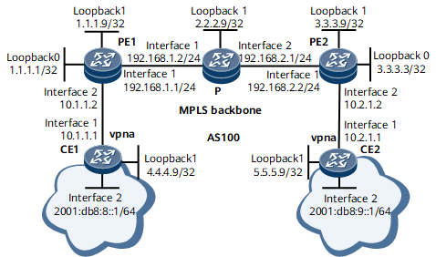
On the network shown in Figure 1, CE1 and CE2 belong to a VPN instance named vpna. If you want to implement communication between the IPv6 networks belong to vpna through an IPv4 network and shield the VPN IPv6 routes on the PEs over the IPv4 network, you can configure the 6VPE function.

Configuration Roadmap
The configuration roadmap is as follows:
Configure an IGP over the IPv4 backbone network to implement communication between PEs.
Configure MPLS and MPLS LDP on each PE and the P to establish an LDP LSP between the PEs.
Configure MP-IBGP on PE1 and PE2 to enable PEs to exchange IPv6 VPN routing information through BGP.
Configure a VPN instance that supports the IPv4 and IPv6 address families on each PE and bind the VPN instance to the PE interface connecting to a CE.
Configure BGP VPN peer relationships between PEs and CEs (tunnel forwarding).
Data Preparation
To complete the configuration, you need the following data:
AS numbers of PEs and CEs
VPN instance name
Attributes of the VPN instance IPv4 and IPv6 address families, such as RDs and route targets
Procedure
- Assign an IPv4 address and IPv6 address to each device interface.
For configuration details, see Configuration Files in this section.
- Configure an IGP over the IPv4 backbone network to implement communication between PEs. IS-IS is used in this example.
For configuration details, see Configuration Files in this section.
- Enable MPLS and MPLS LDP on each device and device interface over the IPv4 backbone network. Create an LDP LSP between PE1 and PE2.
For configuration details, see Configuration Files in this section.
- Set up a BGP VPNv6 peer relationship between the PEs.
# Configure PE1.
[~PE1] bgp 100
[*PE1-bgp] peer 3.3.3.9 as-number 100
[*PE1-bgp] peer 3.3.3.9 connect-interface loopback 1
[*PE1-bgp] ipv6-family vpnv6
[*PE1-bgp-af-vpnv6] peer 3.3.3.9 enable
[*PE1-bgp-af-vpnv6] quit
[*PE1-bgp] quit
[*PE1] commit
# Configure PE2.
[~PE2] bgp 100
[*PE2-bgp] peer 1.1.1.9 as-number 100
[*PE2-bgp] peer 1.1.1.9 connect-interface loopback 1
[*PE2-bgp] ipv6-family vpnv6
[*PE2-bgp-af-vpnv6] peer 1.1.1.9 enable
[*PE2-bgp-af-vpnv6] quit
[*PE2-bgp] quit
[*PE2] commit
After completing the preceding configuration, run the display bgp vpnv6 all peer command on each PE to check information about the BGP VPNv6 peer relationship. The following example uses the command output on PE1.
[~PE1] display bgp vpnv6 all peer
 BGP local router ID : 192.168.1.1
 Local AS number : 100
 Total number of peers : 1                 Peers in established state : 1

  Peer            V          AS  MsgRcvd  MsgSent  OutQ  Up/Down       State     PrefRcv

  3.3.3.9         4         100        4        3     0 00:01:50  Established    0
The command output shows that State is Established, indicating that the BGP VPNv6 peer relationship between PE1 and PE2 has been established.
- On each PE, configure a VPN instance that supports the IPv4 and IPv6 address families and bind the VPN instance to the PE interface connecting to a CE.
# Configure PE1.
[~PE1] ip vpn-instance vpna
[*PE1-vpn-instance-vpna] ipv4-family
[*PE1-vpn-instance-vpna-af-ipv4] route-distinguisher 100:1
[*PE1-vpn-instance-vpna-af-ipv4] vpn-target 1:1
[*PE1-vpn-instance-vpna-af-ipv4] quit
[*PE1-vpn-instance-vpna] ipv6-family
[*PE1-vpn-instance-vpna-af-ipv6] route-distinguisher 100:2
[*PE1-vpn-instance-vpna-af-ipv6] vpn-target 2:2
[*PE1-vpn-instance-vpna-af-ipv6] quit
[*PE1-vpn-instance-vpna] quit
[*PE1] interface gigabitethernet 0/1/8
[*PE1-GigabitEthernet0/1/8] ip binding vpn-instance vpna
[*PE1-GigabitEthernet0/1/8] ip address 10.1.1.2 24
[*PE1-GigabitEthernet0/1/8] quit
[*PE1] interface Loopback 0
[*PE1-LoopBack0] ip binding vpn-instance vpna
[*PE1-LoopBack0] ip address 1.1.1.1 32
[*PE1-LoopBack0] quit
[*PE1] commit
Repeat this step for PE2. For configuration details, see Configuration Files in this section.
- Configure VPN peer relationships between PEs and CEs (tunnel forwarding).
# Configure PE1.
[~PE1] mpls ldp vpn-instance vpna
[*PE1-mpls-ldp-vpn-instance-vpna] lsr-id 1.1.1.1
[*PE1-mpls-ldp-vpn-instance-vpna] quit
[*PE1] ospf 1 vpn-instance vpna
[*PE1-ospf-1] area 0
[*PE1-ospf-1-area-0.0.0.0] network 1.1.1.1 0.0.0.0
[*PE1-ospf-1-area-0.0.0.0] network 10.1.1.0 0.0.0.255
[*PE1-ospf-1-area-0.0.0.0] quit
[*PE1-ospf-1] quit
[*PE1] bgp 100
[*PE1-bgp] vpn-instance vpna
[*PE1-bgp-instance-vpna] peer 4.4.4.9 as-number 100
[*PE1-bgp-instance-vpna] peer 4.4.4.9 connect-interface LoopBack0
[*PE1-bgp-instance-vpna] quit
[*PE1-bgp] ipv6-family vpn-instance vpna
[*PE1-bgp-6-vpna] peer 4.4.4.9 enable
[*PE1-bgp-6-vpna] peer 4.4.4.9 label-route-capability
[*PE1] commit
# Configure CE1.
[~CE1] mpls lsr-id 4.4.4.9
[*CE1] mpls
[*CE1-mpls] mpls ldp
[*CE1-mpls-ldp] quit
[*CE1] ospf 1
[*CE1-ospf-1] area 0
[*CE1-ospf-1-area-0.0.0.0] network 4.4.4.9 0.0.0.0
[*CE1-ospf-1-area-0.0.0.0] network 10.1.1.0 0.0.0.255
[*CE1-ospf-1-area-0.0.0.0] quit
[*CE1-ospf-1] quit
[*CE1] interface gigabitethernet 0/1/0
[*CE1-GigabitEthernet0/1/0] mpls
[*CE1-GigabitEthernet0/1/0] mpls ldp
[*CE1-GigabitEthernet0/1/0] quit
[*CE1] bgp 100
[*CE1-bgp] peer 1.1.1.1 as-number 100
[*CE1-bgp] peer 1.1.1.1 connect-interface LoopBack1
[*CE1-bgp] ipv6-family unicast
[*CE1-bgp-af-ipv6] peer 1.1.1.1 enable
[*CE1-bgp-af-ipv6] peer 1.1.1.1 label-route-capability
[*CE1-bgp-af-ipv6] network 2001:DB8:8:: 64
[*CE1-bgp-af-ipv6] quit
[*CE1-bgp] quit
[*CE1] commit
The configurations of PE2 and CE2 are similar to those of PE1 and CE1, respectively. For configuration details, see Configuration Files in this section.
- Verify the configuration.
After completing the preceding configuration, CE1 and CE2 can learn IPv6 routes from each other and they can ping each other with ping packets carrying the source IP address. The following example uses the command output on CE1.
[~CE1] display ipv6 routing-table
Routing Table : _public_
         Destinations : 7        Routes : 7

Destination  : ::1                                     PrefixLength : 128
NextHop      : ::1                                     Preference   : 0
Cost         : 0                                       Protocol     : Direct
RelayNextHop : ::                                      TunnelID     : 0x0
Interface    : InLoopBack0                             Flags        : D

Destination  : ::FFFF:127.0.0.0                        PrefixLength : 104
NextHop      : ::FFFF:127.0.0.1                        Preference   : 0
Cost         : 0                                       Protocol     : Direct
RelayNextHop : ::                                      TunnelID     : 0x0
Interface    : InLoopBack0                             Flags        : D

Destination  : ::FFFF:127.0.0.1                        PrefixLength : 128
NextHop      : ::1                                     Preference   : 0
Cost         : 0                                       Protocol     : Direct
RelayNextHop : ::                                      TunnelID     : 0x0
Interface    : InLoopBack0                             Flags        : D

Destination  : 2001:DB8:8::                            PrefixLength : 64
NextHop      : 2001:DB8:8::1                           Preference   : 0
Cost         : 0                                       Protocol     : Direct
RelayNextHop : ::                                      TunnelID     : 0x0
Interface    : LoopBack0                               Flags        : D

Destination  : 2001:DB8:8::1                           PrefixLength : 128
NextHop      : ::1                                     Preference   : 0
Cost         : 0                                       Protocol     : Direct
RelayNextHop : ::                                      TunnelID     : 0x0
Interface    : LoopBack0                               Flags        : D

Destination  : 2001:DB8:9::                          PrefixLength : 64
NextHop      : ::FFFF:1.1.1.1                          Preference   : 255
Cost         : 0                                       Protocol     : IBGP
RelayNextHop : ::FFFF:10.1.1.2                         TunnelID     : 0x0000000001004c4b42
Interface    : GigabitEthernet0/1/8                    Flags        : RD

Destination  : FE80::                                  PrefixLength : 10
NextHop      : ::                                      Preference   : 0
Cost         : 0                                       Protocol     : Direct
RelayNextHop : ::                                      TunnelID     : 0x0
Interface    : NULL0                                   Flags        : DB
[~CE1] ping ipv6 -a 2001:db8:8::1 2001:db8:9::1
  PING 2001:db8:9::1 : 56  data bytes, press CTRL_C to break
    Reply from 2001:db8:9::1
    bytes=56 Sequence=1 hop limit=62  time = 170 ms
    Reply from 2001:db8:9::1
    bytes=56 Sequence=2 hop limit=62  time = 140 ms
    Reply from 2001:db8:9::1
    bytes=56 Sequence=3 hop limit=62  time = 150 ms
    Reply from 2001:db8:9::1
    bytes=56 Sequence=4 hop limit=62  time = 140 ms
    Reply from 2001:db8:9::1
    bytes=56 Sequence=5 hop limit=62  time = 170 ms

  --- 2001:db8:9::1 ping statistics ---
    5 packet(s) transmitted
    5 packet(s) received
    0.00% packet loss
    round-trip min/avg/max = 140/154/170 ms
Configuration Files
PE1 configuration file
#
sysname PE1
#
ip vpn-instance vpna
 ipv4-family
  route-distinguisher 100:1
  apply-label per-instance
  vpn-target 1:1 export-extcommunity
  vpn-target 1:1 import-extcommunity
 ipv6-family
  route-distinguisher 100:2
  apply-label per-instance
  vpn-target 2:2 export-extcommunity
  vpn-target 2:2 import-extcommunity
#
mpls lsr-id 1.1.1.9
#
mpls
#
mpls ldp
#
mpls ldp vpn-instance vpna
 lsr-id 1.1.1.1
#
isis 1
 network-entity 10.1111.1111.1111.00
#
interface GigabitEthernet0/1/0
 undo shutdown
 ip address 192.168.1.1 255.255.255.0
 isis enable 1
 mpls
 mpls ldp
#
interface GigabitEthernet0/1/8
 undo shutdown
 ip binding vpn-instance vpna
 ip address 10.1.1.2 255.255.255.0
 mpls
 mpls ldp
#
interface LoopBack0
 ip binding vpn-instance vpna
 ip address 1.1.1.1 255.255.255.255
#
interface LoopBack1
 ip address 1.1.1.9 255.255.255.255
 isis enable 1
#
bgp 100
 peer 3.3.3.9 as-number 100
 peer 3.3.3.9 connect-interface LoopBack1
 #
 ipv4-family unicast
  undo synchronization
  peer 3.3.3.9 enable
 #
 vpn-instance vpna
  peer 4.4.4.9 as-number 100
  peer 4.4.4.9 connect-interface LoopBack0
 #
 ipv6-family vpnv6
  policy vpn-target
  peer 3.3.3.9 enable
 #
 ipv6-family vpn-instance vpna
  peer 4.4.4.9 enable
  peer 4.4.4.9 label-route-capability
#
ospf 1 vpn-instance vpna
 area 0.0.0.0
  network 1.1.1.1 0.0.0.0
  network 10.1.1.0 0.0.0.255
#
return
P configuration file
#
sysname P
#
mpls lsr-id 2.2.2.9
#
mpls
#
mpls ldp
#
isis 1
 network-entity 20.2222.2222.2222.00
#
interface GigabitEthernet0/1/0
 undo shutdown
 ip address 192.168.1.2 255.255.255.0
 isis enable 1
 mpls
 mpls ldp
#
interface GigabitEthernet0/1/8
 undo shutdown
 ip address 192.168.2.1 255.255.255.0
 isis enable 1
 mpls
 mpls ldp
#
interface LoopBack1
 ip address 2.2.2.9 255.255.255.255
 isis enable 1
#
return
PE2 configuration file
#
sysname PE2
#
ip vpn-instance vpna
 ipv4-family
  route-distinguisher 100:1
  apply-label per-instance
  vpn-target 1:1 export-extcommunity
  vpn-target 1:1 import-extcommunity
 ipv6-family
  route-distinguisher 100:2
  apply-label per-instance
  vpn-target 2:2 export-extcommunity
  vpn-target 2:2 import-extcommunity
#
mpls lsr-id 3.3.3.9
#
mpls
#
mpls ldp
#
mpls ldp vpn-instance vpna
 lsr-id 3.3.3.3
#
isis 1
 network-entity 30.3333.3333.3333.00
#
interface GigabitEthernet0/1/0
 undo shutdown
 ip address 192.168.2.2 255.255.255.0
 isis enable 1
 mpls
 mpls ldp
#
interface GigabitEthernet0/1/8
 undo shutdown
 ip binding vpn-instance vpna
 ip address 10.2.1.2 255.255.255.0
 mpls
 mpls ldp
#
interface LoopBack0
 ip binding vpn-instance vpna
 ip address 3.3.3.3 255.255.255.255
#
interface LoopBack1
 ip address 3.3.3.9 255.255.255.255
 isis enable 1
#
bgp 100
 peer 1.1.1.9 as-number 100
 peer 1.1.1.9 connect-interface LoopBack1
 #
 ipv4-family unicast
  undo synchronization
  peer 1.1.1.9 enable
 #
 vpn-instance vpna
  peer 5.5.5.9 as-number 100
  peer 5.5.5.9 connect-interface LoopBack0
 #
 ipv6-family vpnv6
  policy vpn-target
  peer 1.1.1.9 enable
 #
 ipv6-family vpn-instance vpna
  import-route direct
  peer 5.5.5.9 enable
  peer 5.5.5.9 label-route-capability
#
ospf 1 vpn-instance vpna
 area 0.0.0.0
  network 3.3.3.3 0.0.0.0
  network 10.2.1.0 0.0.0.255
#
return
CE1 configuration file
#
sysname CE1
#
mpls lsr-id 4.4.4.9
#
mpls
#
mpls ldp
#
interface GigabitEthernet0/1/0
 undo shutdown
 ip address 10.1.1.1 255.255.255.0
 mpls
 mpls ldp
#
interface LoopBack0
 ipv6 enable
 ipv6 address 2001:DB8:8::1/64
#
interface LoopBack1
 ip address 4.4.4.9 255.255.255.255
#
bgp 100
 peer 1.1.1.1 as-number 100
 peer 1.1.1.1 connect-interface LoopBack1
 #
 ipv4-family unicast
  undo synchronization
  peer 1.1.1.1 enable
 #
 ipv6-family unicast
  undo synchronization
  network 2001:DB8:8:: 64
  peer 1.1.1.1 enable
  peer 1.1.1.1 label-route-capability
#
ospf 1
 area 0.0.0.0
  network 4.4.4.9 0.0.0.0
  network 10.1.1.0 0.0.0.255
#
return
CE2 configuration file
#
sysname CE2
#
mpls lsr-id 5.5.5.9
#
mpls
#
mpls ldp
#
interface GigabitEthernet0/1/0
 undo shutdown
 ip address 10.2.1.1 255.255.255.0
 mpls
 mpls ldp
#
interface LoopBack0
 ipv6 enable
 ipv6 address 2001:DB8:9::1/64
#
interface LoopBack1
 ip address 5.5.5.9 255.255.255.255
#
bgp 100
 peer 3.3.3.3 as-number 100
 peer 3.3.3.3 connect-interface LoopBack1
 #
 ipv4-family unicast
  undo synchronization
  peer 3.3.3.3 enable
 #
 ipv6-family unicast
  undo synchronization
  network 2001:DB8:9:: 64
  peer 3.3.3.3 enable
  peer 3.3.3.3 label-route-capability
#
ospf 1
 area 0.0.0.0
  network 5.5.5.9 0.0.0.0
  network 10.2.1.0 0.0.0.255
#
return