Example for Configuring Frame LM for a PW
This section provides an example for configuring frame loss measurement (LM) for a pseudo wire (PW).
Networking Requirements
As a connection-oriented packet switching technology, Multiprotocol Label Switching Transport Profile (MPLS-TP) is designed to convert a circuit switched transport network to a packet switched transport network. The purpose is to increase the transmission rate on the transport network.
Link reliability must be ensured when MPLS-TP is used. Although users do not sense a change in voice quality if the frame loss ratio on voice links is lower than 10%, for example, the frame loss ratio higher than 20% causes obvious reductions of voice quality.
Frame LM can be used to collect frame loss statistics and evaluate link performance. LM is a performance monitoring function provided by MPLS-TP and is classified as single-ended frame LM or dual-ended frame LM.

The configuration of dual-ended frame LM is used as an example in this section. Regardless of single-ended or dual-ended, DM configurations on PEs are the same except the statistics display configurations.
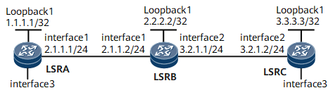
- LSRA and LSRC serve as MEPs.
- LSRB serves as a MIP.
Interfaces 1 through 2 in this example are GE 0/1/0 and GE 0/1/8, respectively.
Device |
Interface |
IP Address |
|---|---|---|
LSRA |
Loopback1 |
1.1.1.1/32 |
GigabitEthernet0/1/0 |
2.1.1.1/24 |
|
LSRB |
Loopback1 |
2.2.2.2/32 |
GigabitEthernet0/1/0 |
2.1.1.2/24 |
|
GigabitEthernet0/1/8 |
3.2.1.1/24 |
|
LSRC |
Loopback1 |
3.3.3.3/32 |
GigabitEthernet0/1/8 |
3.2.1.2/24 |
Configuration Roadmap
The configuration roadmap is as follows:
Create a maintenance entity (ME) instance and bind it to a PW.
Enable continuity check (CC) and connectivity verification (CV) on the MEP and its remote MEP (RMEP).
Configure an alarm threshold for lost frames.
Enable dual-ended frame LM.
Data Preparation
To complete the configuration, you need the following data:
MEG name
ID of the virtual circuit (VC) bound to the ME
Alarm threshold for lost frames
Procedure
- Configure a PW over a bidirectional LSP.
For configuration details, see "Configuration Examples" in HUAWEI NetEngine 8000 F SeriesRouter Configuration Guide - VPN or "Configuration Files" in this section.
- Create an ME instance and bind it to the PW.# Create an ME instance named test on LSRA and bind it to the PW.
[~LSRA] mpls-tp meg test
[*LSRA-mpls-tp-meg-test] me l2vc peer-ip 3.3.3.3 vc-id 30000 vc-type vlan mep-id 1 remote-mep-id 2
# Create an ME instance named test on LSRC and bind it to the PW.[~LSRC] mpls-tp meg test [*LSRC-mpls-tp-meg-test] me l2vc peer-ip 1.1.1.1 vc-id 30000 vc-type vlan mep-id 2 remote-mep-id 1
- Enable CC and CV on the MEP and RMEP.# Enable CC and CV on LSRA.
[~LSRA-mpls-tp-meg-test] cc send enable
[~LSRA-mpls-tp-meg-test] cc receive enable
# Enable CC and CV on LSRC.[~LSRC-mpls-tp-meg-test] cc send enable [~LSRC-mpls-tp-meg-test] cc receive enable
- Enable dual-ended frame LM.# Enable dual-ended frame LM on LSRA.
[~LSRA-mpls-tp-meg-test] lost-measure dual-ended enable
[~LSRA-mpls-tp-meg-test] return
# Enable dual-ended frame LM on LSRC.[~LSRC-mpls-tp-meg-test] lost-measure dual-ended enable [~LSRC-mpls-tp-meg-test] return
- Verify the configuration.
After completing the configurations, run the display mpls-tp oam command on LSRA to view frame loss statistics.
<LSRA> display mpls-tp oam meg test statistic-type lost-measure dual-ended
Dual-end loss measurement statistics:
Index Near-end lost frames Loss ratio Far-end lost frames Loss ratio
1     10                   12.50%     10                  12.50%
Max near-end lost frames:10,frame loss ratio:12.50%
Min near-end lost frames:10,frame loss ratio:12.50%
Average near-end lost frames:10,frame loss ratio:12.50%
Max far-end lost frames:10,frame loss ratio:12.50%
Min far-end lost frames:10,frame loss ratio:12.50%
Average far-end lost frames:10,frame loss ratio:12.50%
Configuration Files
LSRA configuration file
#
 sysname LSRA
#
 mpls lsr-id 1.1.1.1
 mpls
  mpls te
#
 mpls l2vpn
#
 bidirectional static-cr-lsp ingress Tunnel10
  forward nexthop 2.1.1.2 out-label 20
  backward in-label 20
#
pw-template tpatoc
 peer-address 3.3.3.3
 control-word
 tnl-policy tpatoc
#
interface GigabitEthernet0/1/0
 undo shutdown
 ip address 2.1.1.1 255.255.255.0
 mpls
 mpls te
#
interface GigabitEthernet0/1/0.1
 vlan-type dot1q 1
 mpls
 mpls static-l2vc pw-template tpatoc 30000 transmit-vpn-label 101 receive-vpn-label 101
 mpls l2vpn pw traffic-statistics enable
#
interface LoopBack1
 ip address 1.1.1.1 255.255.255.255
#
interface Tunnel10
 ip address unnumbered interface LoopBack1
 tunnel-protocol mpls te
 destination 2.2.2.2
 mpls te signal-protocol cr-static
 mpls te tunnel-id 100
 mpls te bidirectional
 mpls te reserved-for-binding
#
 ip route-static 2.2.2.2 255.255.255.255 2.1.1.2
 ip route-static 3.3.3.3 255.255.255.255 2.1.1.2
#
tunnel-policy tpatoc
 tunnel binding destination 2.2.2.2 te Tunnel10
#
 mpls-tp meg test
  me l2vc peer-ip 3.3.3.3 vc-id 30000 vc-type vlan mep-id 1 remote-mep-id 2
  cc send enable
  cc receive enable
lost-measure dual-ended enable
#
return
LSRB configuration file
#
 sysname LSRB
#
 mpls lsr-id 2.2.2.2
 mpls
  mpls te
#
 bidirectional static-cr-lsp transit lsp1
  forward in-label 20 nexthop 3.2.1.2 out-label 40
  backward in-label 16 nexthop 2.1.1.1 out-label 20
#
interface GigabitEthernet0/1/0
 undo shutdown
 ip address 2.1.1.2 255.255.255.0
 mpls
 mpls te
#
interface GigabitEthernet0/1/8
 undo shutdown
 ip address 3.2.1.1 255.255.255.0
 mpls
 mpls te
#
interface LoopBack1
 ip address 2.2.2.2 255.255.255.255
#
 ip route-static 1.1.1.1 255.255.255.255 2.1.1.1
 ip route-static 3.3.3.3 255.255.255.255 3.2.1.2
#
return
LSRC configuration file
#
 sysname LSRC
#
 mpls lsr-id 3.3.3.3
 mpls
  mpls te
#
 mpls l2vpn
#
 bidirectional static-cr-lsp egress lsp1
  forward in-label 40 lsrid 1.1.1.1 tunnel-id 100
  backward nexthop 3.2.1.1 out-label 16
#
pw-template tpctoa
 peer-address 1.1.1.1
 control-word
 tnl-policy tpctoa
#
interface GigabitEthernet0/1/0
 undo shutdown
 ip address 3.2.1.2 255.255.255.0
 mpls
 mpls te
#
interface GigabitEthernet0/1/0.1
 vlan-type dot1q 1
 mpls static-l2vc pw-template tpctoa 30000 transmit-vpn-label 101 receive-vpn-label
101
 mpls l2vpn pw traffic-statistics enable
#
interface LoopBack1
 ip address 3.3.3.3 255.255.255.255
#
interface Tunnel20
 ip address unnumbered interface LoopBack1
 tunnel-protocol mpls te
 destination 1.1.1.1
 mpls te signal-protocol cr-static
 mpls te tunnel-id 200
 mpls te passive-tunnel
 mpls te binding bidirectional static-cr-lsp egress lsp1
 mpls te reserved-for-binding
#
 ip route-static 1.1.1.1 255.255.255.255 3.2.1.1
 ip route-static 2.2.2.2 255.255.255.255 3.2.1.1
#
tunnel-policy tpctoa
 tunnel binding destination 1.1.1.1 te Tunnel10
#
 mpls-tp meg test
  me l2vc peer-ip 1.1.1.1 vc-id 30000 vc-type vlan mep-id 2 remote-mep-id 1
  cc send enable
  cc receive enable
lost-measure dual-ended enable
#
return